
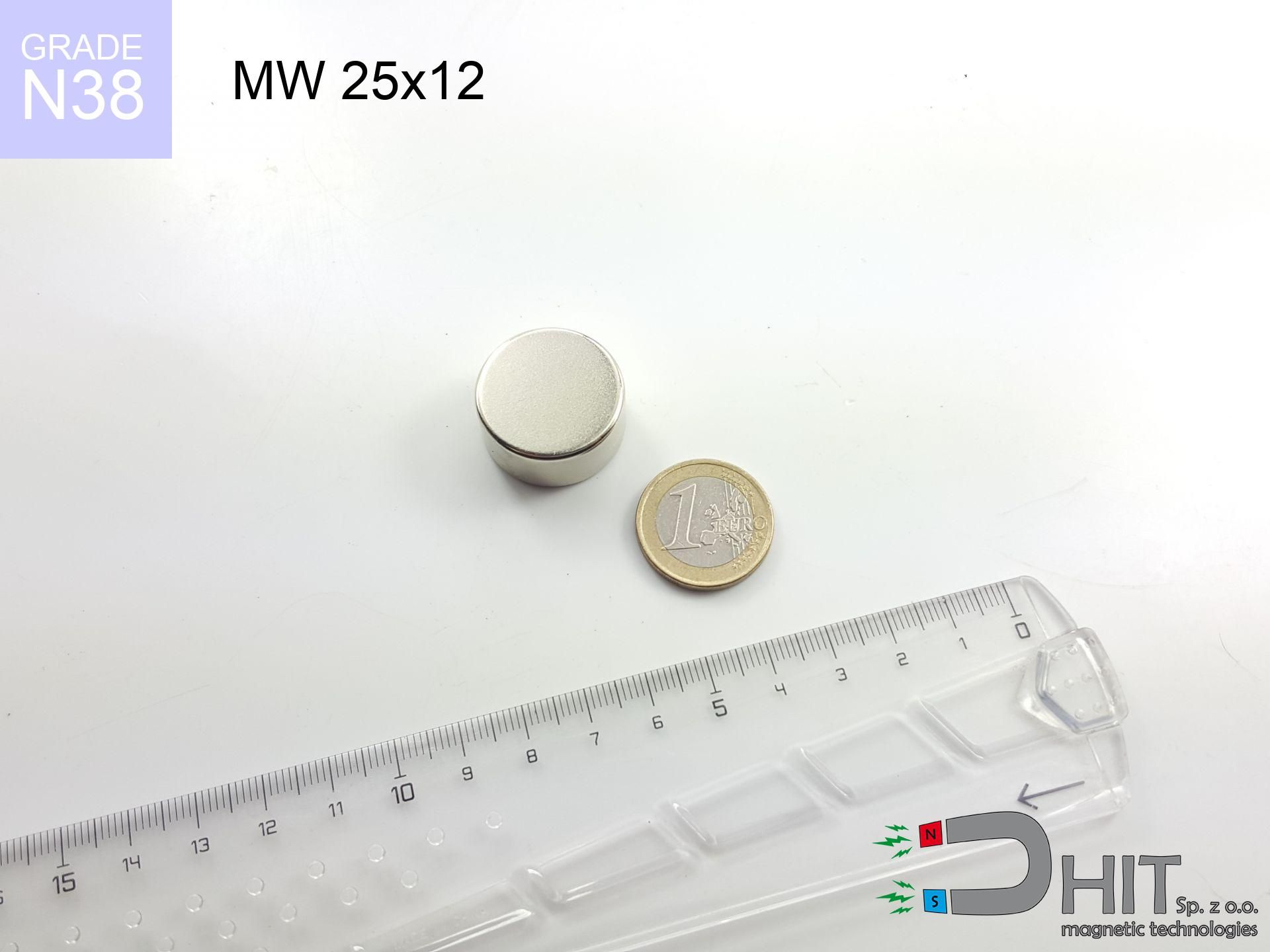
MW 25x12 / N38 - cylindrical magnet
cylindrical magnet
Catalog no 010502
GTIN/EAN: 5906301814986
Diameter Ø
25 mm [±0,1 mm]
Height
12 mm [±0,1 mm]
Weight
44.18 g
Magnetization Direction
↑ axial
Load capacity
19.60 kg / 192.25 N
Magnetic Induction
429.18 mT / 4292 Gs
Coating
[NiCuNi] Nickel
16.64 ZŁ with VAT / pcs + price for transport
13.53 ZŁ net + 23% VAT / pcs
bulk discounts:
Need more?
Call us
+48 22 499 98 98
if you prefer get in touch by means of
inquiry form
our website.
Specifications as well as appearance of magnets can be tested on our
modular calculator.
Orders submitted before 14:00 will be dispatched today!
Product card - MW 25x12 / N38 - cylindrical magnet
Specification / characteristics - MW 25x12 / N38 - cylindrical magnet
| properties | values |
|---|---|
| Cat. no. | 010502 |
| GTIN/EAN | 5906301814986 |
| Production/Distribution | Dhit sp. z o.o. |
| Country of origin | Poland / China / Germany |
| Customs code | 85059029 |
| Diameter Ø | 25 mm [±0,1 mm] |
| Height | 12 mm [±0,1 mm] |
| Weight | 44.18 g |
| Magnetization Direction | ↑ axial |
| Load capacity ~ ? | 19.60 kg / 192.25 N |
| Magnetic Induction ~ ? | 429.18 mT / 4292 Gs |
| Coating | [NiCuNi] Nickel |
| Manufacturing Tolerance | ±0.1 mm |
Magnetic properties of material N38
| properties | values | units |
|---|---|---|
| remenance Br [min. - max.] ? | 12.2-12.6 | kGs |
| remenance Br [min. - max.] ? | 1220-1260 | mT |
| coercivity bHc ? | 10.8-11.5 | kOe |
| coercivity bHc ? | 860-915 | kA/m |
| actual internal force iHc | ≥ 12 | kOe |
| actual internal force iHc | ≥ 955 | kA/m |
| energy density [min. - max.] ? | 36-38 | BH max MGOe |
| energy density [min. - max.] ? | 287-303 | BH max KJ/m |
| max. temperature ? | ≤ 80 | °C |
Physical properties of sintered neodymium magnets Nd2Fe14B at 20°C
| properties | values | units |
|---|---|---|
| Vickers hardness | ≥550 | Hv |
| Density | ≥7.4 | g/cm3 |
| Curie Temperature TC | 312 - 380 | °C |
| Curie Temperature TF | 593 - 716 | °F |
| Specific resistance | 150 | μΩ⋅cm |
| Bending strength | 250 | MPa |
| Compressive strength | 1000~1100 | MPa |
| Thermal expansion parallel (∥) to orientation (M) | (3-4) x 10-6 | °C-1 |
| Thermal expansion perpendicular (⊥) to orientation (M) | -(1-3) x 10-6 | °C-1 |
| Young's modulus | 1.7 x 10⁴ | kg/mm² |
Physical modeling of the product - technical parameters
The following values constitute the result of a mathematical simulation. Results were calculated on algorithms for the material Nd2Fe14B. Real-world parameters might slightly differ from theoretical values. Use these data as a supplementary guide for designers.
Table 1: Static pull force (force vs gap) - interaction chart
MW 25x12 / N38
| Distance (mm) | Induction (Gauss) / mT | Pull Force (kg/lbs/g/N) | Risk Status |
|---|---|---|---|
| 0 mm |
4291 Gs
429.1 mT
|
19.60 kg / 43.21 lbs
19600.0 g / 192.3 N
|
crushing |
| 1 mm |
3975 Gs
397.5 mT
|
16.82 kg / 37.08 lbs
16820.5 g / 165.0 N
|
crushing |
| 2 mm |
3645 Gs
364.5 mT
|
14.15 kg / 31.19 lbs
14147.5 g / 138.8 N
|
crushing |
| 3 mm |
3316 Gs
331.6 mT
|
11.71 kg / 25.81 lbs
11707.5 g / 114.9 N
|
crushing |
| 5 mm |
2692 Gs
269.2 mT
|
7.72 kg / 17.02 lbs
7718.0 g / 75.7 N
|
warning |
| 10 mm |
1518 Gs
151.8 mT
|
2.45 kg / 5.41 lbs
2451.8 g / 24.1 N
|
warning |
| 15 mm |
863 Gs
86.3 mT
|
0.79 kg / 1.75 lbs
793.5 g / 7.8 N
|
safe |
| 20 mm |
517 Gs
51.7 mT
|
0.29 kg / 0.63 lbs
285.1 g / 2.8 N
|
safe |
| 30 mm |
219 Gs
21.9 mT
|
0.05 kg / 0.11 lbs
51.2 g / 0.5 N
|
safe |
| 50 mm |
63 Gs
6.3 mT
|
0.00 kg / 0.01 lbs
4.2 g / 0.0 N
|
safe |
Table 2: Shear load (vertical surface)
MW 25x12 / N38
| Distance (mm) | Friction coefficient | Pull Force (kg/lbs/g/N) |
|---|---|---|
| 0 mm | Stal (~0.2) |
3.92 kg / 8.64 lbs
3920.0 g / 38.5 N
|
| 1 mm | Stal (~0.2) |
3.36 kg / 7.42 lbs
3364.0 g / 33.0 N
|
| 2 mm | Stal (~0.2) |
2.83 kg / 6.24 lbs
2830.0 g / 27.8 N
|
| 3 mm | Stal (~0.2) |
2.34 kg / 5.16 lbs
2342.0 g / 23.0 N
|
| 5 mm | Stal (~0.2) |
1.54 kg / 3.40 lbs
1544.0 g / 15.1 N
|
| 10 mm | Stal (~0.2) |
0.49 kg / 1.08 lbs
490.0 g / 4.8 N
|
| 15 mm | Stal (~0.2) |
0.16 kg / 0.35 lbs
158.0 g / 1.5 N
|
| 20 mm | Stal (~0.2) |
0.06 kg / 0.13 lbs
58.0 g / 0.6 N
|
| 30 mm | Stal (~0.2) |
0.01 kg / 0.02 lbs
10.0 g / 0.1 N
|
| 50 mm | Stal (~0.2) |
0.00 kg / 0.00 lbs
0.0 g / 0.0 N
|
Table 3: Wall mounting (shearing) - behavior on slippery surfaces
MW 25x12 / N38
| Surface type | Friction coefficient / % Mocy | Max load (kg/lbs/g/N) |
|---|---|---|
| Raw steel |
µ = 0.3
30% Nominalnej Siły
|
5.88 kg / 12.96 lbs
5880.0 g / 57.7 N
|
| Painted steel (standard) |
µ = 0.2
20% Nominalnej Siły
|
3.92 kg / 8.64 lbs
3920.0 g / 38.5 N
|
| Oily/slippery steel |
µ = 0.1
10% Nominalnej Siły
|
1.96 kg / 4.32 lbs
1960.0 g / 19.2 N
|
| Magnet with anti-slip rubber |
µ = 0.5
50% Nominalnej Siły
|
9.80 kg / 21.61 lbs
9800.0 g / 96.1 N
|
Table 4: Steel thickness (saturation) - power losses
MW 25x12 / N38
| Steel thickness (mm) | % power | Real pull force (kg/lbs/g/N) |
|---|---|---|
| 0.5 mm |
|
0.98 kg / 2.16 lbs
980.0 g / 9.6 N
|
| 1 mm |
|
2.45 kg / 5.40 lbs
2450.0 g / 24.0 N
|
| 2 mm |
|
4.90 kg / 10.80 lbs
4900.0 g / 48.1 N
|
| 3 mm |
|
7.35 kg / 16.20 lbs
7350.0 g / 72.1 N
|
| 5 mm |
|
12.25 kg / 27.01 lbs
12250.0 g / 120.2 N
|
| 10 mm |
|
19.60 kg / 43.21 lbs
19600.0 g / 192.3 N
|
| 11 mm |
|
19.60 kg / 43.21 lbs
19600.0 g / 192.3 N
|
| 12 mm |
|
19.60 kg / 43.21 lbs
19600.0 g / 192.3 N
|
Table 5: Thermal resistance (material behavior) - resistance threshold
MW 25x12 / N38
| Ambient temp. (°C) | Power loss | Remaining pull (kg/lbs/g/N) | Status |
|---|---|---|---|
| 20 °C | 0.0% |
19.60 kg / 43.21 lbs
19600.0 g / 192.3 N
|
OK |
| 40 °C | -2.2% |
19.17 kg / 42.26 lbs
19168.8 g / 188.0 N
|
OK |
| 60 °C | -4.4% |
18.74 kg / 41.31 lbs
18737.6 g / 183.8 N
|
|
| 80 °C | -6.6% |
18.31 kg / 40.36 lbs
18306.4 g / 179.6 N
|
|
| 100 °C | -28.8% |
13.96 kg / 30.77 lbs
13955.2 g / 136.9 N
|
Table 6: Two magnets (repulsion) - field range
MW 25x12 / N38
| Gap (mm) | Attraction (kg/lbs) (N-S) | Lateral Force (kg/lbs/g/N) | Repulsion (kg/lbs) (N-N) |
|---|---|---|---|
| 0 mm |
55.71 kg / 122.82 lbs
5 494 Gs
|
8.36 kg / 18.42 lbs
8357 g / 82.0 N
|
N/A |
| 1 mm |
51.78 kg / 114.14 lbs
8 273 Gs
|
7.77 kg / 17.12 lbs
7766 g / 76.2 N
|
46.60 kg / 102.73 lbs
~0 Gs
|
| 2 mm |
47.81 kg / 105.40 lbs
7 949 Gs
|
7.17 kg / 15.81 lbs
7172 g / 70.4 N
|
43.03 kg / 94.86 lbs
~0 Gs
|
| 3 mm |
43.94 kg / 96.88 lbs
7 621 Gs
|
6.59 kg / 14.53 lbs
6592 g / 64.7 N
|
39.55 kg / 87.19 lbs
~0 Gs
|
| 5 mm |
36.65 kg / 80.80 lbs
6 960 Gs
|
5.50 kg / 12.12 lbs
5497 g / 53.9 N
|
32.98 kg / 72.72 lbs
~0 Gs
|
| 10 mm |
21.94 kg / 48.36 lbs
5 385 Gs
|
3.29 kg / 7.25 lbs
3291 g / 32.3 N
|
19.74 kg / 43.53 lbs
~0 Gs
|
| 20 mm |
6.97 kg / 15.36 lbs
3 035 Gs
|
1.05 kg / 2.30 lbs
1045 g / 10.3 N
|
6.27 kg / 13.83 lbs
~0 Gs
|
| 50 mm |
0.33 kg / 0.72 lbs
657 Gs
|
0.05 kg / 0.11 lbs
49 g / 0.5 N
|
0.29 kg / 0.65 lbs
~0 Gs
|
| 60 mm |
0.15 kg / 0.32 lbs
439 Gs
|
0.02 kg / 0.05 lbs
22 g / 0.2 N
|
0.13 kg / 0.29 lbs
~0 Gs
|
| 70 mm |
0.07 kg / 0.16 lbs
306 Gs
|
0.01 kg / 0.02 lbs
11 g / 0.1 N
|
0.06 kg / 0.14 lbs
~0 Gs
|
| 80 mm |
0.04 kg / 0.08 lbs
221 Gs
|
0.01 kg / 0.01 lbs
6 g / 0.1 N
|
0.03 kg / 0.07 lbs
~0 Gs
|
| 90 mm |
0.02 kg / 0.05 lbs
165 Gs
|
0.00 kg / 0.01 lbs
3 g / 0.0 N
|
0.02 kg / 0.04 lbs
~0 Gs
|
| 100 mm |
0.01 kg / 0.03 lbs
126 Gs
|
0.00 kg / 0.00 lbs
2 g / 0.0 N
|
0.01 kg / 0.02 lbs
~0 Gs
|
Table 7: Safety (HSE) (implants) - warnings
MW 25x12 / N38
| Object / Device | Limit (Gauss) / mT | Safe distance |
|---|---|---|
| Pacemaker | 5 Gs (0.5 mT) | 13.0 cm |
| Hearing aid | 10 Gs (1.0 mT) | 10.0 cm |
| Timepiece | 20 Gs (2.0 mT) | 8.0 cm |
| Phone / Smartphone | 40 Gs (4.0 mT) | 6.0 cm |
| Remote | 50 Gs (5.0 mT) | 5.5 cm |
| Payment card | 400 Gs (40.0 mT) | 2.5 cm |
| HDD hard drive | 600 Gs (60.0 mT) | 2.0 cm |
Table 8: Impact energy (kinetic energy) - warning
MW 25x12 / N38
| Start from (mm) | Speed (km/h) | Energy (J) | Predicted outcome |
|---|---|---|---|
| 10 mm |
22.84 km/h
(6.35 m/s)
|
0.89 J | |
| 30 mm |
36.85 km/h
(10.24 m/s)
|
2.31 J | |
| 50 mm |
47.51 km/h
(13.20 m/s)
|
3.85 J | |
| 100 mm |
67.17 km/h
(18.66 m/s)
|
7.69 J |
Table 9: Coating parameters (durability)
MW 25x12 / N38
| Technical parameter | Value / Description |
|---|---|
| Coating type | [NiCuNi] Nickel |
| Layer structure | Nickel - Copper - Nickel |
| Layer thickness | 10-20 µm |
| Salt spray test (SST) ? | 24 h |
| Recommended environment | Indoors only (dry) |
Table 10: Construction data (Flux)
MW 25x12 / N38
| Parameter | Value | SI Unit / Description |
|---|---|---|
| Magnetic Flux | 21 413 Mx | 214.1 µWb |
| Pc Coefficient | 0.57 | Low (Flat) |
Table 11: Hydrostatics and buoyancy
MW 25x12 / N38
| Environment | Effective steel pull | Effect |
|---|---|---|
| Air (land) | 19.60 kg | Standard |
| Water (riverbed) |
22.44 kg
(+2.84 kg buoyancy gain)
|
+14.5% |
1. Vertical hold
*Caution: On a vertical surface, the magnet holds just ~20% of its perpendicular strength.
2. Steel thickness impact
*Thin steel (e.g. 0.5mm PC case) drastically weakens the holding force.
3. Temperature resistance
*For standard magnets, the critical limit is 80°C.
4. Demagnetization curve and operating point (B-H)
chart generated for the permeance coefficient Pc (Permeance Coefficient) = 0.57
This simulation demonstrates the magnetic stability of the selected magnet under specific geometric conditions. The solid red line represents the demagnetization curve (material potential), while the dashed blue line is the load line based on the magnet's geometry. The Pc (Permeance Coefficient), also known as the load line slope, is a dimensionless value that describes the relationship between the magnet's shape and its magnetic stability. The intersection of these two lines (the black dot) is the operating point — it determines the actual magnetic flux density generated by the magnet in this specific configuration. A higher Pc value means the magnet is more 'slender' (tall relative to its area), resulting in a higher operating point and better resistance to irreversible demagnetization caused by external fields or temperature. A value of 0.42 is relatively low (typical for flat magnets), meaning the operating point is closer to the 'knee' of the curve — caution is advised when operating at temperatures near the maximum limit to avoid strength loss.
Chemical composition
| iron (Fe) | 64% – 68% |
| neodymium (Nd) | 29% – 32% |
| boron (B) | 1.1% – 1.2% |
| dysprosium (Dy) | 0.5% – 2.0% |
| coating (Ni-Cu-Ni) | < 0.05% |
Ecology and recycling (GPSR)
| recyclability (EoL) | 100% |
| recycled raw materials | ~10% (pre-cons) |
| carbon footprint | low / zredukowany |
| waste code (EWC) | 16 02 16 |
Check out more products


Advantages and disadvantages of rare earth magnets.
Pros
- They virtually do not lose power, because even after 10 years the decline in efficiency is only ~1% (according to literature),
- Magnets very well resist against loss of magnetization caused by foreign field sources,
- The use of an elegant coating of noble metals (nickel, gold, silver) causes the element to be more visually attractive,
- Neodymium magnets achieve maximum magnetic induction on a small area, which ensures high operational effectiveness,
- Due to their durability and thermal resistance, neodymium magnets are capable of operate (depending on the shape) even at high temperatures reaching 230°C or more...
- Considering the possibility of precise forming and adaptation to specialized solutions, magnetic components can be produced in a broad palette of geometric configurations, which makes them more universal,
- Significant place in advanced technology sectors – they find application in data components, electric drive systems, diagnostic systems, as well as other advanced devices.
- Compactness – despite small sizes they offer powerful magnetic field, making them ideal for precision applications
Limitations
- At strong impacts they can break, therefore we recommend placing them in strong housings. A metal housing provides additional protection against damage and increases the magnet's durability.
- When exposed to high temperature, neodymium magnets experience a drop in power. Often, when the temperature exceeds 80°C, their power decreases (depending on the size and shape of the magnet). For those who need magnets for extreme conditions, we offer [AH] versions withstanding up to 230°C
- They rust in a humid environment - during use outdoors we recommend using waterproof magnets e.g. in rubber, plastic
- Limited ability of producing threads in the magnet and complex shapes - preferred is casing - magnet mounting.
- Potential hazard resulting from small fragments of magnets are risky, if swallowed, which gains importance in the context of child safety. It is also worth noting that small elements of these magnets are able to complicate diagnosis medical after entering the body.
- High unit price – neodymium magnets cost more than other types of magnets (e.g. ferrite), which hinders application in large quantities
Lifting parameters
Maximum lifting force for a neodymium magnet – what it depends on?
- with the application of a yoke made of low-carbon steel, guaranteeing full magnetic saturation
- with a cross-section no less than 10 mm
- with an ideally smooth contact surface
- under conditions of no distance (metal-to-metal)
- for force acting at a right angle (pull-off, not shear)
- at ambient temperature room level
Magnet lifting force in use – key factors
- Air gap (betwixt the magnet and the plate), since even a microscopic distance (e.g. 0.5 mm) can cause a decrease in force by up to 50% (this also applies to varnish, corrosion or debris).
- Direction of force – highest force is obtained only during pulling at a 90° angle. The shear force of the magnet along the surface is typically several times lower (approx. 1/5 of the lifting capacity).
- Element thickness – for full efficiency, the steel must be adequately massive. Thin sheet limits the lifting capacity (the magnet "punches through" it).
- Steel grade – ideal substrate is high-permeability steel. Hardened steels may generate lower lifting capacity.
- Surface condition – smooth surfaces ensure maximum contact, which increases force. Uneven metal reduce efficiency.
- Thermal conditions – NdFeB sinters have a sensitivity to temperature. At higher temperatures they are weaker, and in frost they can be stronger (up to a certain limit).
Lifting capacity testing was performed on plates with a smooth surface of optimal thickness, under perpendicular forces, whereas under parallel forces the lifting capacity is smaller. Additionally, even a minimal clearance between the magnet’s surface and the plate lowers the lifting capacity.
Safety rules for work with neodymium magnets
Handling guide
Use magnets with awareness. Their huge power can surprise even professionals. Be vigilant and respect their force.
Maximum temperature
Do not overheat. Neodymium magnets are sensitive to temperature. If you need resistance above 80°C, ask us about HT versions (H, SH, UH).
Fragile material
NdFeB magnets are ceramic materials, which means they are fragile like glass. Clashing of two magnets will cause them shattering into shards.
Electronic devices
Equipment safety: Neodymium magnets can ruin payment cards and sensitive devices (pacemakers, medical aids, mechanical watches).
Do not drill into magnets
Combustion risk: Rare earth powder is explosive. Do not process magnets without safety gear as this risks ignition.
Magnetic interference
Remember: neodymium magnets generate a field that interferes with precision electronics. Keep a separation from your phone, device, and navigation systems.
ICD Warning
Medical warning: Neodymium magnets can turn off heart devices and defibrillators. Stay away if you have medical devices.
Finger safety
Danger of trauma: The attraction force is so great that it can result in blood blisters, pinching, and even bone fractures. Use thick gloves.
No play value
Strictly keep magnets out of reach of children. Choking hazard is significant, and the consequences of magnets clamping inside the body are fatal.
Allergic reactions
A percentage of the population experience a contact allergy to nickel, which is the standard coating for NdFeB magnets. Prolonged contact may cause an allergic reaction. It is best to wear safety gloves.
Tabela kosztu i czasu dostawy
Płatność przed wysyłką:

GLS kurier
Przesyłka będzie u Ciebie za 2-3 dni
14.99 ZŁ

InPost Paczkomaty 24/7
Przesyłka będzie u Ciebie za 1-2 dni
12.30 ZŁ
Płatność przy odbiorze (pobranie):
GLS kurier
Przesyłka będzie u Ciebie za 1-2 dni
23.00 ZŁ
Rate the product
Your rating