
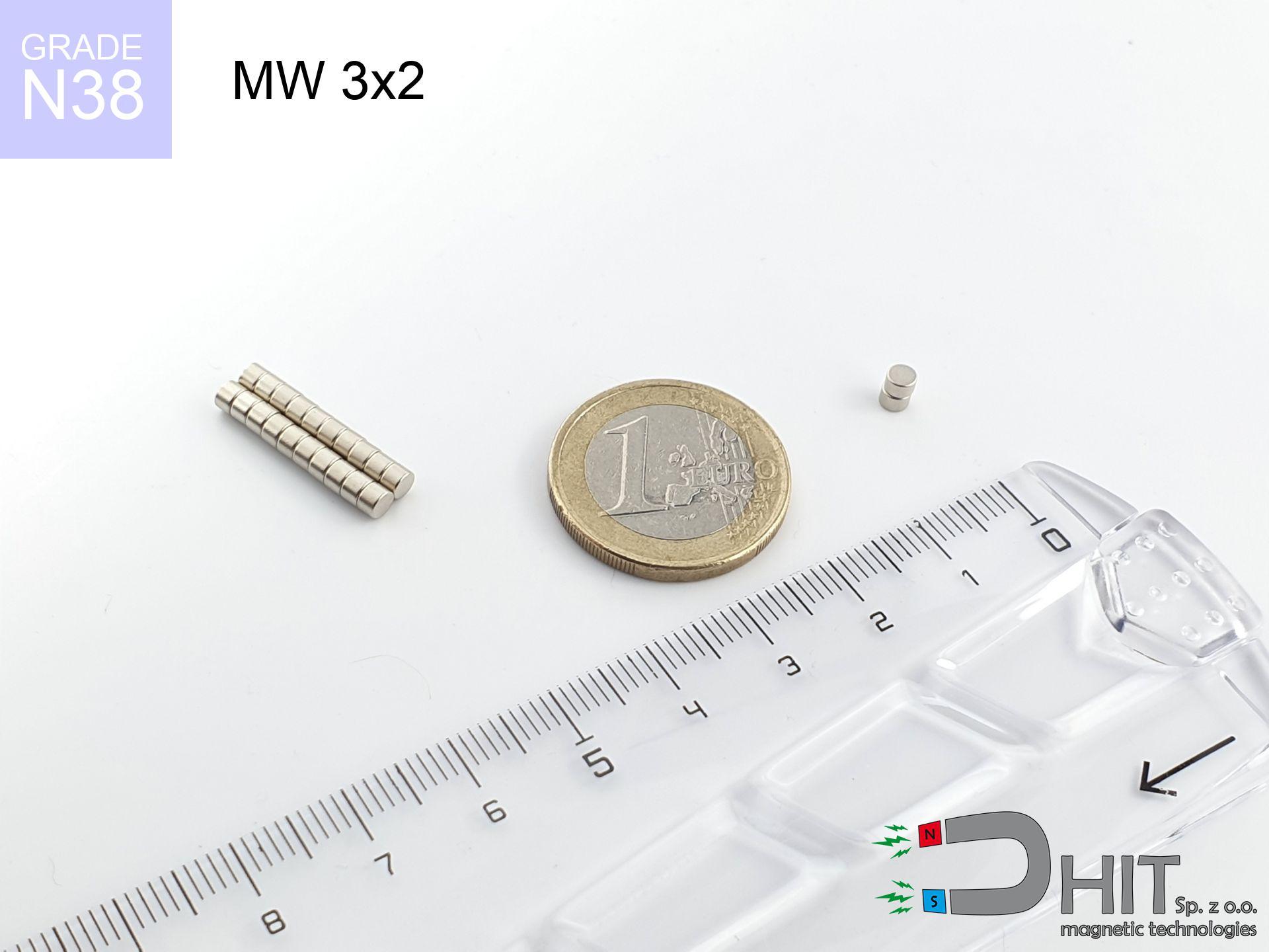
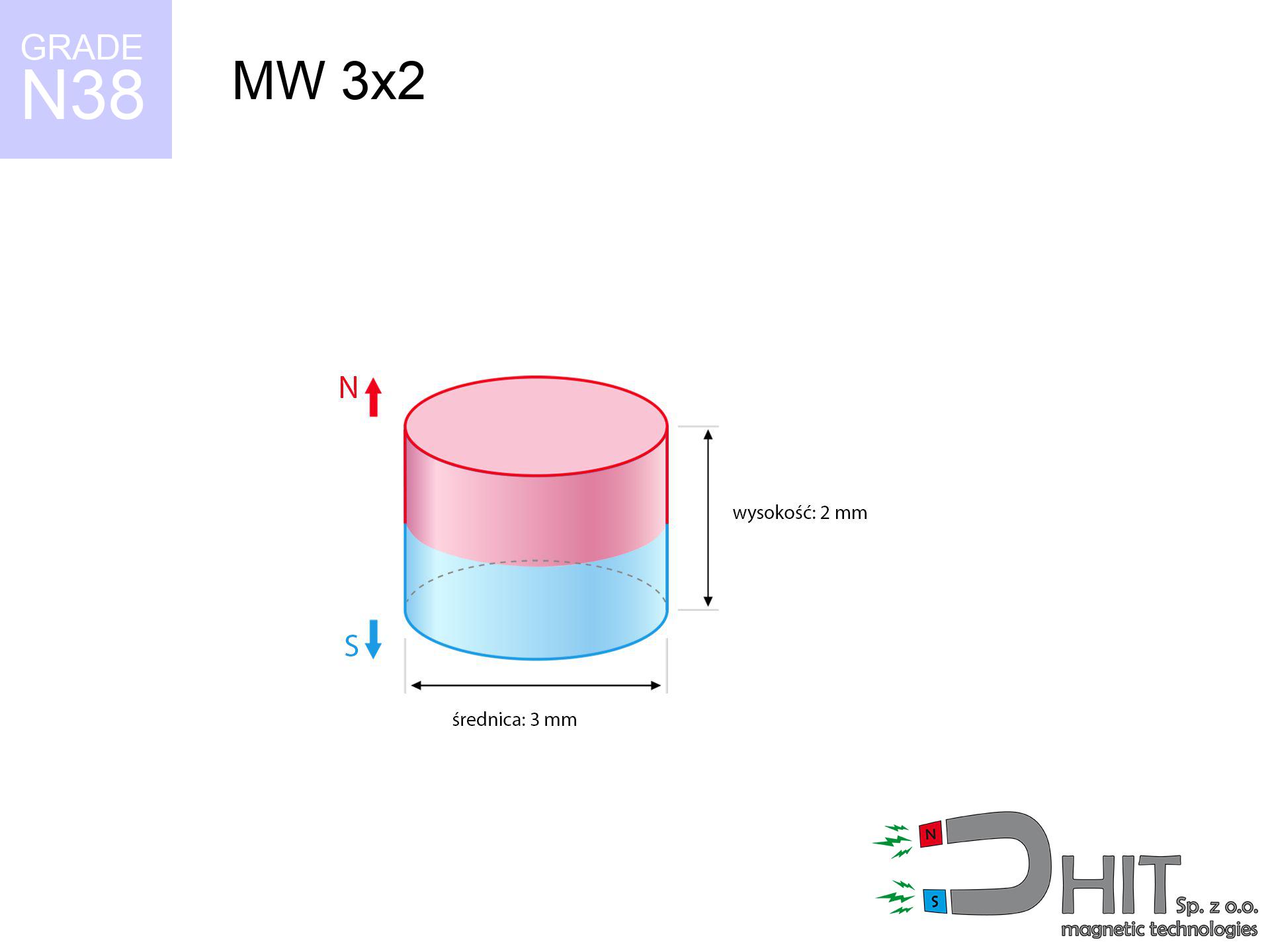
MW 3x2 / N38 - cylindrical magnet
cylindrical magnet
Catalog no 010064
GTIN/EAN: 5906301810636
Diameter Ø
3 mm [±0,1 mm]
Height
2 mm [±0,1 mm]
Weight
0.11 g
Magnetization Direction
↑ axial
Load capacity
0.30 kg / 2.99 N
Magnetic Induction
493.99 mT / 4940 Gs
Coating
[NiCuNi] Nickel
0.1476 ZŁ with VAT / pcs + price for transport
0.1200 ZŁ net + 23% VAT / pcs
bulk discounts:
Need more?
Give us a call
+48 888 99 98 98
otherwise send us a note by means of
contact form
the contact page.
Parameters and appearance of magnets can be verified on our
our magnetic calculator.
Same-day shipping for orders placed before 14:00.
Product card - MW 3x2 / N38 - cylindrical magnet
Specification / characteristics - MW 3x2 / N38 - cylindrical magnet
| properties | values |
|---|---|
| Cat. no. | 010064 |
| GTIN/EAN | 5906301810636 |
| Production/Distribution | Dhit sp. z o.o. |
| Country of origin | Poland / China / Germany |
| Customs code | 85059029 |
| Diameter Ø | 3 mm [±0,1 mm] |
| Height | 2 mm [±0,1 mm] |
| Weight | 0.11 g |
| Magnetization Direction | ↑ axial |
| Load capacity ~ ? | 0.30 kg / 2.99 N |
| Magnetic Induction ~ ? | 493.99 mT / 4940 Gs |
| Coating | [NiCuNi] Nickel |
| Manufacturing Tolerance | ±0.1 mm |
Magnetic properties of material N38
| properties | values | units |
|---|---|---|
| remenance Br [min. - max.] ? | 12.2-12.6 | kGs |
| remenance Br [min. - max.] ? | 1220-1260 | mT |
| coercivity bHc ? | 10.8-11.5 | kOe |
| coercivity bHc ? | 860-915 | kA/m |
| actual internal force iHc | ≥ 12 | kOe |
| actual internal force iHc | ≥ 955 | kA/m |
| energy density [min. - max.] ? | 36-38 | BH max MGOe |
| energy density [min. - max.] ? | 287-303 | BH max KJ/m |
| max. temperature ? | ≤ 80 | °C |
Physical properties of sintered neodymium magnets Nd2Fe14B at 20°C
| properties | values | units |
|---|---|---|
| Vickers hardness | ≥550 | Hv |
| Density | ≥7.4 | g/cm3 |
| Curie Temperature TC | 312 - 380 | °C |
| Curie Temperature TF | 593 - 716 | °F |
| Specific resistance | 150 | μΩ⋅cm |
| Bending strength | 250 | MPa |
| Compressive strength | 1000~1100 | MPa |
| Thermal expansion parallel (∥) to orientation (M) | (3-4) x 10-6 | °C-1 |
| Thermal expansion perpendicular (⊥) to orientation (M) | -(1-3) x 10-6 | °C-1 |
| Young's modulus | 1.7 x 10⁴ | kg/mm² |
Technical simulation of the product - report
These information represent the outcome of a engineering analysis. Values are based on models for the material Nd2Fe14B. Operational conditions might slightly deviate from the simulation results. Please consider these data as a supplementary guide during assembly planning.
Table 1: Static force (pull vs distance) - characteristics
MW 3x2 / N38
| Distance (mm) | Induction (Gauss) / mT | Pull Force (kg/lbs/g/N) | Risk Status |
|---|---|---|---|
| 0 mm |
4928 Gs
492.8 mT
|
0.30 kg / 0.66 pounds
300.0 g / 2.9 N
|
safe |
| 1 mm |
2106 Gs
210.6 mT
|
0.05 kg / 0.12 pounds
54.8 g / 0.5 N
|
safe |
| 2 mm |
845 Gs
84.5 mT
|
0.01 kg / 0.02 pounds
8.8 g / 0.1 N
|
safe |
| 3 mm |
393 Gs
39.3 mT
|
0.00 kg / 0.00 pounds
1.9 g / 0.0 N
|
safe |
| 5 mm |
124 Gs
12.4 mT
|
0.00 kg / 0.00 pounds
0.2 g / 0.0 N
|
safe |
| 10 mm |
21 Gs
2.1 mT
|
0.00 kg / 0.00 pounds
0.0 g / 0.0 N
|
safe |
| 15 mm |
7 Gs
0.7 mT
|
0.00 kg / 0.00 pounds
0.0 g / 0.0 N
|
safe |
| 20 mm |
3 Gs
0.3 mT
|
0.00 kg / 0.00 pounds
0.0 g / 0.0 N
|
safe |
| 30 mm |
1 Gs
0.1 mT
|
0.00 kg / 0.00 pounds
0.0 g / 0.0 N
|
safe |
| 50 mm |
0 Gs
0.0 mT
|
0.00 kg / 0.00 pounds
0.0 g / 0.0 N
|
safe |
Table 2: Slippage load (wall)
MW 3x2 / N38
| Distance (mm) | Friction coefficient | Pull Force (kg/lbs/g/N) |
|---|---|---|
| 0 mm | Stal (~0.2) |
0.06 kg / 0.13 pounds
60.0 g / 0.6 N
|
| 1 mm | Stal (~0.2) |
0.01 kg / 0.02 pounds
10.0 g / 0.1 N
|
| 2 mm | Stal (~0.2) |
0.00 kg / 0.00 pounds
2.0 g / 0.0 N
|
| 3 mm | Stal (~0.2) |
0.00 kg / 0.00 pounds
0.0 g / 0.0 N
|
| 5 mm | Stal (~0.2) |
0.00 kg / 0.00 pounds
0.0 g / 0.0 N
|
| 10 mm | Stal (~0.2) |
0.00 kg / 0.00 pounds
0.0 g / 0.0 N
|
| 15 mm | Stal (~0.2) |
0.00 kg / 0.00 pounds
0.0 g / 0.0 N
|
| 20 mm | Stal (~0.2) |
0.00 kg / 0.00 pounds
0.0 g / 0.0 N
|
| 30 mm | Stal (~0.2) |
0.00 kg / 0.00 pounds
0.0 g / 0.0 N
|
| 50 mm | Stal (~0.2) |
0.00 kg / 0.00 pounds
0.0 g / 0.0 N
|
Table 3: Wall mounting (sliding) - behavior on slippery surfaces
MW 3x2 / N38
| Surface type | Friction coefficient / % Mocy | Max load (kg/lbs/g/N) |
|---|---|---|
| Raw steel |
µ = 0.3
30% Nominalnej Siły
|
0.09 kg / 0.20 pounds
90.0 g / 0.9 N
|
| Painted steel (standard) |
µ = 0.2
20% Nominalnej Siły
|
0.06 kg / 0.13 pounds
60.0 g / 0.6 N
|
| Oily/slippery steel |
µ = 0.1
10% Nominalnej Siły
|
0.03 kg / 0.07 pounds
30.0 g / 0.3 N
|
| Magnet with anti-slip rubber |
µ = 0.5
50% Nominalnej Siły
|
0.15 kg / 0.33 pounds
150.0 g / 1.5 N
|
Table 4: Material efficiency (saturation) - power losses
MW 3x2 / N38
| Steel thickness (mm) | % power | Real pull force (kg/lbs/g/N) |
|---|---|---|
| 0.5 mm |
|
0.03 kg / 0.07 pounds
30.0 g / 0.3 N
|
| 1 mm |
|
0.08 kg / 0.17 pounds
75.0 g / 0.7 N
|
| 2 mm |
|
0.15 kg / 0.33 pounds
150.0 g / 1.5 N
|
| 3 mm |
|
0.22 kg / 0.50 pounds
225.0 g / 2.2 N
|
| 5 mm |
|
0.30 kg / 0.66 pounds
300.0 g / 2.9 N
|
| 10 mm |
|
0.30 kg / 0.66 pounds
300.0 g / 2.9 N
|
| 11 mm |
|
0.30 kg / 0.66 pounds
300.0 g / 2.9 N
|
| 12 mm |
|
0.30 kg / 0.66 pounds
300.0 g / 2.9 N
|
Table 5: Thermal resistance (stability) - resistance threshold
MW 3x2 / N38
| Ambient temp. (°C) | Power loss | Remaining pull (kg/lbs/g/N) | Status |
|---|---|---|---|
| 20 °C | 0.0% |
0.30 kg / 0.66 pounds
300.0 g / 2.9 N
|
OK |
| 40 °C | -2.2% |
0.29 kg / 0.65 pounds
293.4 g / 2.9 N
|
OK |
| 60 °C | -4.4% |
0.29 kg / 0.63 pounds
286.8 g / 2.8 N
|
OK |
| 80 °C | -6.6% |
0.28 kg / 0.62 pounds
280.2 g / 2.7 N
|
|
| 100 °C | -28.8% |
0.21 kg / 0.47 pounds
213.6 g / 2.1 N
|
Table 6: Magnet-Magnet interaction (attraction) - field collision
MW 3x2 / N38
| Gap (mm) | Attraction (kg/lbs) (N-S) | Shear Strength (kg/lbs/g/N) | Repulsion (kg/lbs) (N-N) |
|---|---|---|---|
| 0 mm |
1.06 kg / 2.33 pounds
5 766 Gs
|
0.16 kg / 0.35 pounds
159 g / 1.6 N
|
N/A |
| 1 mm |
0.49 kg / 1.08 pounds
6 712 Gs
|
0.07 kg / 0.16 pounds
74 g / 0.7 N
|
0.44 kg / 0.97 pounds
~0 Gs
|
| 2 mm |
0.19 kg / 0.43 pounds
4 213 Gs
|
0.03 kg / 0.06 pounds
29 g / 0.3 N
|
0.17 kg / 0.38 pounds
~0 Gs
|
| 3 mm |
0.08 kg / 0.17 pounds
2 629 Gs
|
0.01 kg / 0.02 pounds
11 g / 0.1 N
|
0.07 kg / 0.15 pounds
~0 Gs
|
| 5 mm |
0.01 kg / 0.03 pounds
1 131 Gs
|
0.00 kg / 0.00 pounds
2 g / 0.0 N
|
0.01 kg / 0.03 pounds
~0 Gs
|
| 10 mm |
0.00 kg / 0.00 pounds
248 Gs
|
0.00 kg / 0.00 pounds
0 g / 0.0 N
|
0.00 kg / 0.00 pounds
~0 Gs
|
| 20 mm |
0.00 kg / 0.00 pounds
41 Gs
|
0.00 kg / 0.00 pounds
0 g / 0.0 N
|
0.00 kg / 0.00 pounds
~0 Gs
|
| 50 mm |
0.00 kg / 0.00 pounds
3 Gs
|
0.00 kg / 0.00 pounds
0 g / 0.0 N
|
0.00 kg / 0.00 pounds
~0 Gs
|
| 60 mm |
0.00 kg / 0.00 pounds
2 Gs
|
0.00 kg / 0.00 pounds
0 g / 0.0 N
|
0.00 kg / 0.00 pounds
~0 Gs
|
| 70 mm |
0.00 kg / 0.00 pounds
1 Gs
|
0.00 kg / 0.00 pounds
0 g / 0.0 N
|
0.00 kg / 0.00 pounds
~0 Gs
|
| 80 mm |
0.00 kg / 0.00 pounds
1 Gs
|
0.00 kg / 0.00 pounds
0 g / 0.0 N
|
0.00 kg / 0.00 pounds
~0 Gs
|
| 90 mm |
0.00 kg / 0.00 pounds
1 Gs
|
0.00 kg / 0.00 pounds
0 g / 0.0 N
|
0.00 kg / 0.00 pounds
~0 Gs
|
| 100 mm |
0.00 kg / 0.00 pounds
0 Gs
|
0.00 kg / 0.00 pounds
0 g / 0.0 N
|
0.00 kg / 0.00 pounds
~0 Gs
|
Table 7: Hazards (electronics) - warnings
MW 3x2 / N38
| Object / Device | Limit (Gauss) / mT | Safe distance |
|---|---|---|
| Pacemaker | 5 Gs (0.5 mT) | 2.0 cm |
| Hearing aid | 10 Gs (1.0 mT) | 1.5 cm |
| Mechanical watch | 20 Gs (2.0 mT) | 1.5 cm |
| Phone / Smartphone | 40 Gs (4.0 mT) | 1.0 cm |
| Remote | 50 Gs (5.0 mT) | 1.0 cm |
| Payment card | 400 Gs (40.0 mT) | 0.5 cm |
| HDD hard drive | 600 Gs (60.0 mT) | 0.5 cm |
Table 8: Dynamics (kinetic energy) - warning
MW 3x2 / N38
| Start from (mm) | Speed (km/h) | Energy (J) | Predicted outcome |
|---|---|---|---|
| 10 mm |
52.67 km/h
(14.63 m/s)
|
0.01 J | |
| 30 mm |
91.22 km/h
(25.34 m/s)
|
0.04 J | |
| 50 mm |
117.77 km/h
(32.71 m/s)
|
0.06 J | |
| 100 mm |
166.55 km/h
(46.26 m/s)
|
0.12 J |
Table 9: Anti-corrosion coating durability
MW 3x2 / N38
| Technical parameter | Value / Description |
|---|---|
| Coating type | [NiCuNi] Nickel |
| Layer structure | Nickel - Copper - Nickel |
| Layer thickness | 10-20 µm |
| Salt spray test (SST) ? | 24 h |
| Recommended environment | Indoors only (dry) |
Table 10: Construction data (Flux)
MW 3x2 / N38
| Parameter | Value | SI Unit / Description |
|---|---|---|
| Magnetic Flux | 353 Mx | 3.5 µWb |
| Pc Coefficient | 0.71 | High (Stable) |
Table 11: Hydrostatics and buoyancy
MW 3x2 / N38
| Environment | Effective steel pull | Effect |
|---|---|---|
| Air (land) | 0.30 kg | Standard |
| Water (riverbed) |
0.34 kg
(+0.04 kg buoyancy gain)
|
+14.5% |
1. Shear force
*Note: On a vertical wall, the magnet holds merely approx. 20-30% of its nominal pull.
2. Efficiency vs thickness
*Thin steel (e.g. 0.5mm PC case) severely weakens the holding force.
3. Power loss vs temp
*For N38 grade, the safety limit is 80°C.
4. Demagnetization curve and operating point (B-H)
chart generated for the permeance coefficient Pc (Permeance Coefficient) = 0.71
The chart above illustrates the magnetic characteristics of the material within the second quadrant of the hysteresis loop. The solid red line represents the demagnetization curve (material potential), while the dashed blue line is the load line based on the magnet's geometry. The Pc (Permeance Coefficient), also known as the load line slope, is a dimensionless value that describes the relationship between the magnet's shape and its magnetic stability. The intersection of these two lines (the black dot) is the operating point — it determines the actual magnetic flux density generated by the magnet in this specific configuration. A higher Pc value means the magnet is more 'slender' (tall relative to its area), resulting in a higher operating point and better resistance to irreversible demagnetization caused by external fields or temperature. A value of 0.42 is relatively low (typical for flat magnets), meaning the operating point is closer to the 'knee' of the curve — caution is advised when operating at temperatures near the maximum limit to avoid strength loss.
Chemical composition
| iron (Fe) | 64% – 68% |
| neodymium (Nd) | 29% – 32% |
| boron (B) | 1.1% – 1.2% |
| dysprosium (Dy) | 0.5% – 2.0% |
| coating (Ni-Cu-Ni) | < 0.05% |
Ecology and recycling (GPSR)
| recyclability (EoL) | 100% |
| recycled raw materials | ~10% (pre-cons) |
| carbon footprint | low / zredukowany |
| waste code (EWC) | 16 02 16 |
See also products

![HH 42x8.8 [M6] / N38 - through hole magnetic holder](https://cdn3.dhit.pl/graphics/products/hh-42x8.8-m6-hin.jpg "HH 42x8.8 [M6] / N38 - through hole magnetic holder")


Pros and cons of neodymium magnets.
Advantages
- They do not lose strength, even during around ten years – the decrease in lifting capacity is only ~1% (theoretically),
- They retain their magnetic properties even under external field action,
- Thanks to the shiny finish, the plating of Ni-Cu-Ni, gold-plated, or silver gives an professional appearance,
- Neodymium magnets ensure maximum magnetic induction on a small area, which allows for strong attraction,
- Neodymium magnets are characterized by very high magnetic induction on the magnet surface and are able to act (depending on the form) even at a temperature of 230°C or more...
- Possibility of custom creating as well as optimizing to individual applications,
- Universal use in electronics industry – they are utilized in mass storage devices, drive modules, precision medical tools, also modern systems.
- Compactness – despite small sizes they offer powerful magnetic field, making them ideal for precision applications
Limitations
- At strong impacts they can crack, therefore we advise placing them in steel cases. A metal housing provides additional protection against damage and increases the magnet's durability.
- We warn that neodymium magnets can reduce their strength at high temperatures. To prevent this, we suggest our specialized [AH] magnets, which work effectively even at 230°C.
- When exposed to humidity, magnets usually rust. To use them in conditions outside, it is recommended to use protective magnets, such as those in rubber or plastics, which prevent oxidation and corrosion.
- Limited ability of creating threads in the magnet and complex shapes - recommended is cover - mounting mechanism.
- Potential hazard related to microscopic parts of magnets are risky, in case of ingestion, which gains importance in the context of child health protection. It is also worth noting that small components of these devices can complicate diagnosis medical when they are in the body.
- Higher cost of purchase is a significant factor to consider compared to ceramic magnets, especially in budget applications
Lifting parameters
Maximum holding power of the magnet – what it depends on?
- on a block made of structural steel, effectively closing the magnetic flux
- with a thickness minimum 10 mm
- with a plane perfectly flat
- with direct contact (no impurities)
- for force acting at a right angle (in the magnet axis)
- in temp. approx. 20°C
What influences lifting capacity in practice
- Gap between surfaces – every millimeter of distance (caused e.g. by veneer or unevenness) drastically reduces the pulling force, often by half at just 0.5 mm.
- Force direction – remember that the magnet has greatest strength perpendicularly. Under sliding down, the capacity drops significantly, often to levels of 20-30% of the nominal value.
- Element thickness – for full efficiency, the steel must be adequately massive. Thin sheet limits the lifting capacity (the magnet "punches through" it).
- Material composition – different alloys reacts the same. Alloy additives worsen the attraction effect.
- Surface structure – the more even the surface, the better the adhesion and stronger the hold. Roughness acts like micro-gaps.
- Thermal conditions – NdFeB sinters have a negative temperature coefficient. At higher temperatures they are weaker, and at low temperatures they can be stronger (up to a certain limit).
Lifting capacity was measured using a steel plate with a smooth surface of optimal thickness (min. 20 mm), under perpendicular detachment force, whereas under attempts to slide the magnet the lifting capacity is smaller. In addition, even a small distance between the magnet’s surface and the plate decreases the lifting capacity.
Safe handling of neodymium magnets
Flammability
Fire hazard: Rare earth powder is explosive. Avoid machining magnets without safety gear as this may cause fire.
Medical interference
People with a ICD must keep an large gap from magnets. The magnetic field can interfere with the functioning of the implant.
Permanent damage
Standard neodymium magnets (grade N) lose magnetization when the temperature goes above 80°C. The loss of strength is permanent.
Choking Hazard
Strictly store magnets out of reach of children. Choking hazard is significant, and the consequences of magnets connecting inside the body are very dangerous.
Serious injuries
Watch your fingers. Two powerful magnets will snap together immediately with a force of massive weight, destroying everything in their path. Be careful!
Threat to navigation
A powerful magnetic field negatively affects the operation of magnetometers in smartphones and navigation systems. Keep magnets near a device to prevent damaging the sensors.
Respect the power
Use magnets with awareness. Their powerful strength can shock even professionals. Be vigilant and do not underestimate their power.
Protective goggles
NdFeB magnets are sintered ceramics, which means they are fragile like glass. Collision of two magnets leads to them breaking into small pieces.
Nickel allergy
A percentage of the population experience a contact allergy to Ni, which is the typical protective layer for neodymium magnets. Frequent touching might lead to an allergic reaction. We strongly advise wear safety gloves.
Cards and drives
Data protection: Strong magnets can damage payment cards and sensitive devices (pacemakers, hearing aids, timepieces).
Tabela kosztu i czasu dostawy
Płatność przed wysyłką:

GLS kurier
Przesyłka będzie u Ciebie za 2-3 dni
14.99 ZŁ

InPost Paczkomaty 24/7
Przesyłka będzie u Ciebie za 1-2 dni
12.30 ZŁ
Płatność przy odbiorze (pobranie):
GLS kurier
Przesyłka będzie u Ciebie za 1-2 dni
23.00 ZŁ
Rate the product
Your rating