
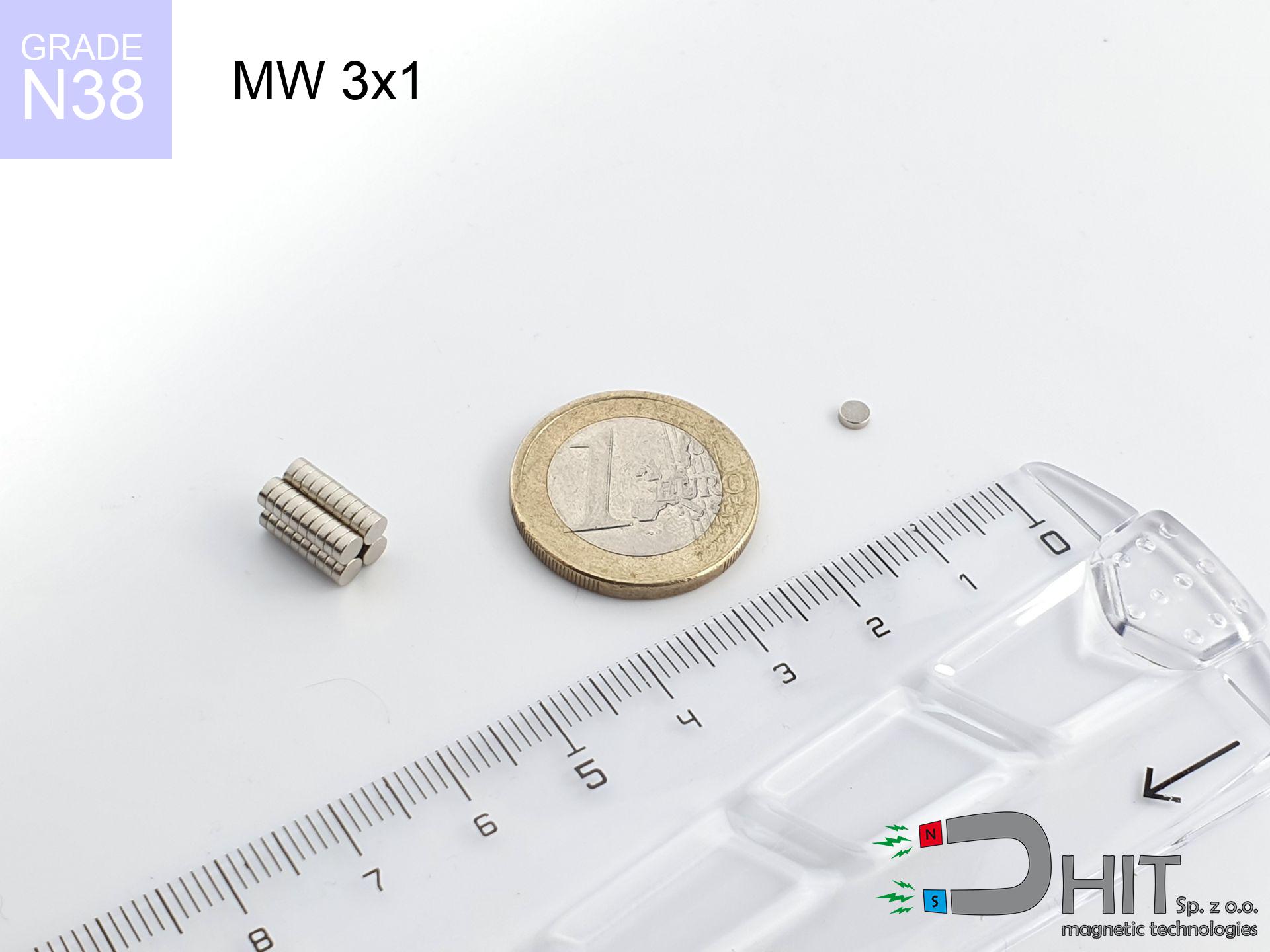
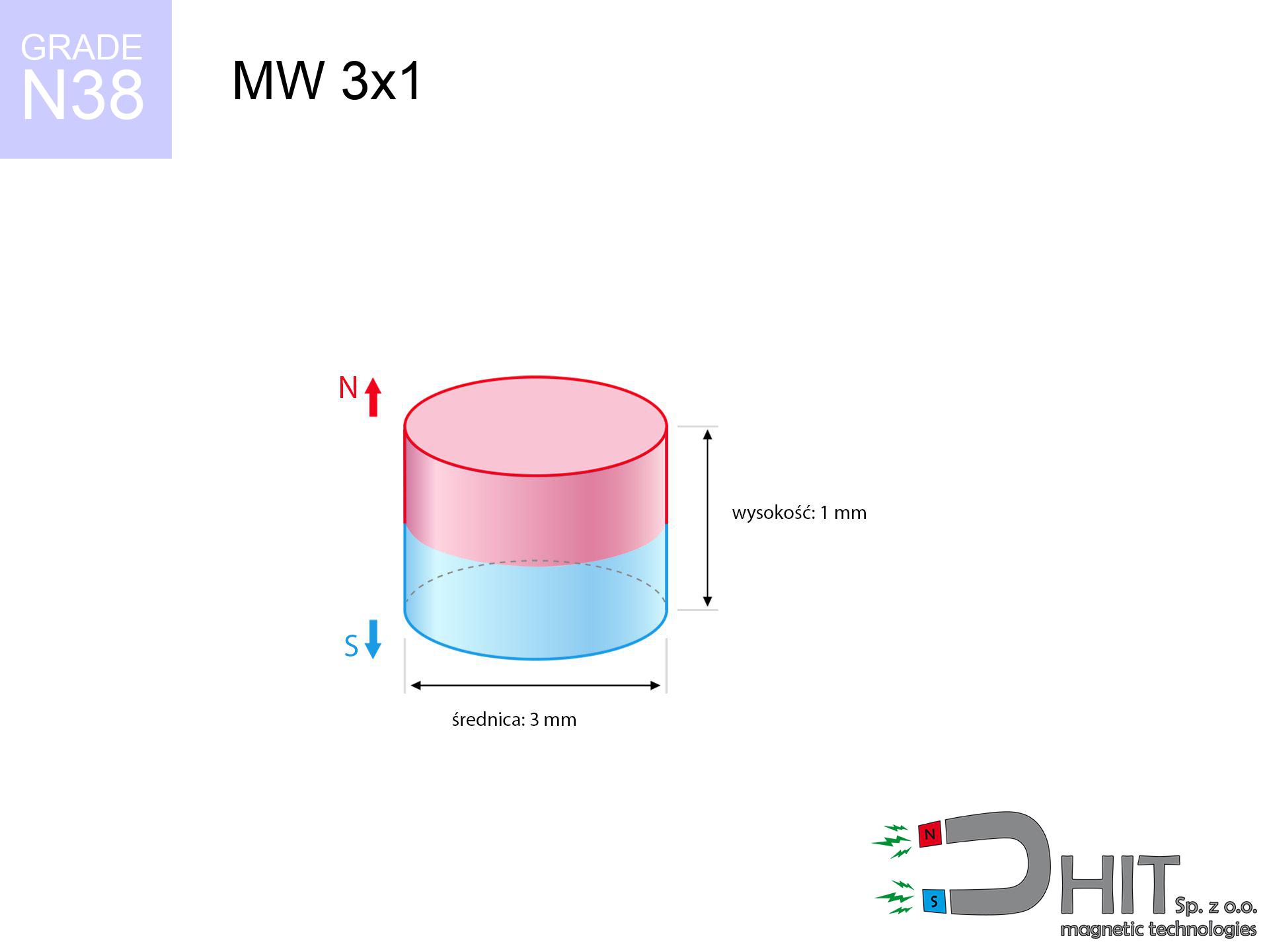
MW 3x1 / N38 - cylindrical magnet
cylindrical magnet
Catalog no 010063
GTIN/EAN: 5906301810629
Diameter Ø
3 mm [±0,1 mm]
Height
1 mm [±0,1 mm]
Weight
0.05 g
Magnetization Direction
↑ axial
Load capacity
0.21 kg / 2.10 N
Magnetic Induction
342.82 mT / 3428 Gs
Coating
[NiCuNi] Nickel
0.1353 ZŁ with VAT / pcs + price for transport
0.1100 ZŁ net + 23% VAT / pcs
bulk discounts:
Need more?
Give us a call
+48 22 499 98 98
otherwise get in touch by means of
request form
the contact page.
Specifications and shape of magnets can be checked on our
power calculator.
Same-day shipping for orders placed before 14:00.
Technical details - MW 3x1 / N38 - cylindrical magnet
Specification / characteristics - MW 3x1 / N38 - cylindrical magnet
| properties | values |
|---|---|
| Cat. no. | 010063 |
| GTIN/EAN | 5906301810629 |
| Production/Distribution | Dhit sp. z o.o. |
| Country of origin | Poland / China / Germany |
| Customs code | 85059029 |
| Diameter Ø | 3 mm [±0,1 mm] |
| Height | 1 mm [±0,1 mm] |
| Weight | 0.05 g |
| Magnetization Direction | ↑ axial |
| Load capacity ~ ? | 0.21 kg / 2.10 N |
| Magnetic Induction ~ ? | 342.82 mT / 3428 Gs |
| Coating | [NiCuNi] Nickel |
| Manufacturing Tolerance | ±0.1 mm |
Magnetic properties of material N38
| properties | values | units |
|---|---|---|
| remenance Br [min. - max.] ? | 12.2-12.6 | kGs |
| remenance Br [min. - max.] ? | 1220-1260 | mT |
| coercivity bHc ? | 10.8-11.5 | kOe |
| coercivity bHc ? | 860-915 | kA/m |
| actual internal force iHc | ≥ 12 | kOe |
| actual internal force iHc | ≥ 955 | kA/m |
| energy density [min. - max.] ? | 36-38 | BH max MGOe |
| energy density [min. - max.] ? | 287-303 | BH max KJ/m |
| max. temperature ? | ≤ 80 | °C |
Physical properties of sintered neodymium magnets Nd2Fe14B at 20°C
| properties | values | units |
|---|---|---|
| Vickers hardness | ≥550 | Hv |
| Density | ≥7.4 | g/cm3 |
| Curie Temperature TC | 312 - 380 | °C |
| Curie Temperature TF | 593 - 716 | °F |
| Specific resistance | 150 | μΩ⋅cm |
| Bending strength | 250 | MPa |
| Compressive strength | 1000~1100 | MPa |
| Thermal expansion parallel (∥) to orientation (M) | (3-4) x 10-6 | °C-1 |
| Thermal expansion perpendicular (⊥) to orientation (M) | -(1-3) x 10-6 | °C-1 |
| Young's modulus | 1.7 x 10⁴ | kg/mm² |
Technical analysis of the assembly - report
These data are the result of a physical simulation. Results were calculated on models for the class Nd2Fe14B. Actual performance may differ from theoretical values. Treat these data as a supplementary guide when designing systems.
Table 1: Static force (pull vs distance) - characteristics
MW 3x1 / N38
| Distance (mm) | Induction (Gauss) / mT | Pull Force (kg/lbs/g/N) | Risk Status |
|---|---|---|---|
| 0 mm |
3422 Gs
342.2 mT
|
0.21 kg / 0.46 LBS
210.0 g / 2.1 N
|
weak grip |
| 1 mm |
1521 Gs
152.1 mT
|
0.04 kg / 0.09 LBS
41.5 g / 0.4 N
|
weak grip |
| 2 mm |
585 Gs
58.5 mT
|
0.01 kg / 0.01 LBS
6.1 g / 0.1 N
|
weak grip |
| 3 mm |
260 Gs
26.0 mT
|
0.00 kg / 0.00 LBS
1.2 g / 0.0 N
|
weak grip |
| 5 mm |
76 Gs
7.6 mT
|
0.00 kg / 0.00 LBS
0.1 g / 0.0 N
|
weak grip |
| 10 mm |
12 Gs
1.2 mT
|
0.00 kg / 0.00 LBS
0.0 g / 0.0 N
|
weak grip |
| 15 mm |
4 Gs
0.4 mT
|
0.00 kg / 0.00 LBS
0.0 g / 0.0 N
|
weak grip |
| 20 mm |
2 Gs
0.2 mT
|
0.00 kg / 0.00 LBS
0.0 g / 0.0 N
|
weak grip |
| 30 mm |
0 Gs
0.0 mT
|
0.00 kg / 0.00 LBS
0.0 g / 0.0 N
|
weak grip |
| 50 mm |
0 Gs
0.0 mT
|
0.00 kg / 0.00 LBS
0.0 g / 0.0 N
|
weak grip |
Table 2: Slippage load (wall)
MW 3x1 / N38
| Distance (mm) | Friction coefficient | Pull Force (kg/lbs/g/N) |
|---|---|---|
| 0 mm | Stal (~0.2) |
0.04 kg / 0.09 LBS
42.0 g / 0.4 N
|
| 1 mm | Stal (~0.2) |
0.01 kg / 0.02 LBS
8.0 g / 0.1 N
|
| 2 mm | Stal (~0.2) |
0.00 kg / 0.00 LBS
2.0 g / 0.0 N
|
| 3 mm | Stal (~0.2) |
0.00 kg / 0.00 LBS
0.0 g / 0.0 N
|
| 5 mm | Stal (~0.2) |
0.00 kg / 0.00 LBS
0.0 g / 0.0 N
|
| 10 mm | Stal (~0.2) |
0.00 kg / 0.00 LBS
0.0 g / 0.0 N
|
| 15 mm | Stal (~0.2) |
0.00 kg / 0.00 LBS
0.0 g / 0.0 N
|
| 20 mm | Stal (~0.2) |
0.00 kg / 0.00 LBS
0.0 g / 0.0 N
|
| 30 mm | Stal (~0.2) |
0.00 kg / 0.00 LBS
0.0 g / 0.0 N
|
| 50 mm | Stal (~0.2) |
0.00 kg / 0.00 LBS
0.0 g / 0.0 N
|
Table 3: Wall mounting (sliding) - behavior on slippery surfaces
MW 3x1 / N38
| Surface type | Friction coefficient / % Mocy | Max load (kg/lbs/g/N) |
|---|---|---|
| Raw steel |
µ = 0.3
30% Nominalnej Siły
|
0.06 kg / 0.14 LBS
63.0 g / 0.6 N
|
| Painted steel (standard) |
µ = 0.2
20% Nominalnej Siły
|
0.04 kg / 0.09 LBS
42.0 g / 0.4 N
|
| Oily/slippery steel |
µ = 0.1
10% Nominalnej Siły
|
0.02 kg / 0.05 LBS
21.0 g / 0.2 N
|
| Magnet with anti-slip rubber |
µ = 0.5
50% Nominalnej Siły
|
0.11 kg / 0.23 LBS
105.0 g / 1.0 N
|
Table 4: Material efficiency (saturation) - sheet metal selection
MW 3x1 / N38
| Steel thickness (mm) | % power | Real pull force (kg/lbs/g/N) |
|---|---|---|
| 0.5 mm |
|
0.02 kg / 0.05 LBS
21.0 g / 0.2 N
|
| 1 mm |
|
0.05 kg / 0.12 LBS
52.5 g / 0.5 N
|
| 2 mm |
|
0.11 kg / 0.23 LBS
105.0 g / 1.0 N
|
| 3 mm |
|
0.16 kg / 0.35 LBS
157.5 g / 1.5 N
|
| 5 mm |
|
0.21 kg / 0.46 LBS
210.0 g / 2.1 N
|
| 10 mm |
|
0.21 kg / 0.46 LBS
210.0 g / 2.1 N
|
| 11 mm |
|
0.21 kg / 0.46 LBS
210.0 g / 2.1 N
|
| 12 mm |
|
0.21 kg / 0.46 LBS
210.0 g / 2.1 N
|
Table 5: Thermal stability (material behavior) - power drop
MW 3x1 / N38
| Ambient temp. (°C) | Power loss | Remaining pull (kg/lbs/g/N) | Status |
|---|---|---|---|
| 20 °C | 0.0% |
0.21 kg / 0.46 LBS
210.0 g / 2.1 N
|
OK |
| 40 °C | -2.2% |
0.21 kg / 0.45 LBS
205.4 g / 2.0 N
|
OK |
| 60 °C | -4.4% |
0.20 kg / 0.44 LBS
200.8 g / 2.0 N
|
|
| 80 °C | -6.6% |
0.20 kg / 0.43 LBS
196.1 g / 1.9 N
|
|
| 100 °C | -28.8% |
0.15 kg / 0.33 LBS
149.5 g / 1.5 N
|
Table 6: Magnet-Magnet interaction (repulsion) - forces in the system
MW 3x1 / N38
| Gap (mm) | Attraction (kg/lbs) (N-S) | Lateral Force (kg/lbs/g/N) | Repulsion (kg/lbs) (N-N) |
|---|---|---|---|
| 0 mm |
0.51 kg / 1.12 LBS
4 928 Gs
|
0.08 kg / 0.17 LBS
77 g / 0.8 N
|
N/A |
| 1 mm |
0.26 kg / 0.56 LBS
4 847 Gs
|
0.04 kg / 0.08 LBS
38 g / 0.4 N
|
0.23 kg / 0.51 LBS
~0 Gs
|
| 2 mm |
0.10 kg / 0.22 LBS
3 042 Gs
|
0.02 kg / 0.03 LBS
15 g / 0.1 N
|
0.09 kg / 0.20 LBS
~0 Gs
|
| 3 mm |
0.04 kg / 0.08 LBS
1 865 Gs
|
0.01 kg / 0.01 LBS
6 g / 0.1 N
|
0.03 kg / 0.08 LBS
~0 Gs
|
| 5 mm |
0.01 kg / 0.01 LBS
764 Gs
|
0.00 kg / 0.00 LBS
1 g / 0.0 N
|
0.00 kg / 0.00 LBS
~0 Gs
|
| 10 mm |
0.00 kg / 0.00 LBS
153 Gs
|
0.00 kg / 0.00 LBS
0 g / 0.0 N
|
0.00 kg / 0.00 LBS
~0 Gs
|
| 20 mm |
0.00 kg / 0.00 LBS
23 Gs
|
0.00 kg / 0.00 LBS
0 g / 0.0 N
|
0.00 kg / 0.00 LBS
~0 Gs
|
| 50 mm |
0.00 kg / 0.00 LBS
2 Gs
|
0.00 kg / 0.00 LBS
0 g / 0.0 N
|
0.00 kg / 0.00 LBS
~0 Gs
|
| 60 mm |
0.00 kg / 0.00 LBS
1 Gs
|
0.00 kg / 0.00 LBS
0 g / 0.0 N
|
0.00 kg / 0.00 LBS
~0 Gs
|
| 70 mm |
0.00 kg / 0.00 LBS
1 Gs
|
0.00 kg / 0.00 LBS
0 g / 0.0 N
|
0.00 kg / 0.00 LBS
~0 Gs
|
| 80 mm |
0.00 kg / 0.00 LBS
0 Gs
|
0.00 kg / 0.00 LBS
0 g / 0.0 N
|
0.00 kg / 0.00 LBS
~0 Gs
|
| 90 mm |
0.00 kg / 0.00 LBS
0 Gs
|
0.00 kg / 0.00 LBS
0 g / 0.0 N
|
0.00 kg / 0.00 LBS
~0 Gs
|
| 100 mm |
0.00 kg / 0.00 LBS
0 Gs
|
0.00 kg / 0.00 LBS
0 g / 0.0 N
|
0.00 kg / 0.00 LBS
~0 Gs
|
Table 7: Protective zones (implants) - precautionary measures
MW 3x1 / N38
| Object / Device | Limit (Gauss) / mT | Safe distance |
|---|---|---|
| Pacemaker | 5 Gs (0.5 mT) | 1.5 cm |
| Hearing aid | 10 Gs (1.0 mT) | 1.5 cm |
| Timepiece | 20 Gs (2.0 mT) | 1.0 cm |
| Mobile device | 40 Gs (4.0 mT) | 1.0 cm |
| Car key | 50 Gs (5.0 mT) | 1.0 cm |
| Payment card | 400 Gs (40.0 mT) | 0.5 cm |
| HDD hard drive | 600 Gs (60.0 mT) | 0.5 cm |
Table 8: Impact energy (kinetic energy) - warning
MW 3x1 / N38
| Start from (mm) | Speed (km/h) | Energy (J) | Predicted outcome |
|---|---|---|---|
| 10 mm |
65.36 km/h
(18.16 m/s)
|
0.01 J | |
| 30 mm |
113.21 km/h
(31.45 m/s)
|
0.02 J | |
| 50 mm |
146.15 km/h
(40.60 m/s)
|
0.04 J | |
| 100 mm |
206.68 km/h
(57.41 m/s)
|
0.08 J |
Table 9: Anti-corrosion coating durability
MW 3x1 / N38
| Technical parameter | Value / Description |
|---|---|
| Coating type | [NiCuNi] Nickel |
| Layer structure | Nickel - Copper - Nickel |
| Layer thickness | 10-20 µm |
| Salt spray test (SST) ? | 24 h |
| Recommended environment | Indoors only (dry) |
Table 10: Construction data (Flux)
MW 3x1 / N38
| Parameter | Value | SI Unit / Description |
|---|---|---|
| Magnetic Flux | 257 Mx | 2.6 µWb |
| Pc Coefficient | 0.44 | Low (Flat) |
Table 11: Hydrostatics and buoyancy
MW 3x1 / N38
| Environment | Effective steel pull | Effect |
|---|---|---|
| Air (land) | 0.21 kg | Standard |
| Water (riverbed) |
0.24 kg
(+0.03 kg buoyancy gain)
|
+14.5% |
1. Wall mount (shear)
*Note: On a vertical wall, the magnet holds just approx. 20-30% of its max power.
2. Steel thickness impact
*Thin steel (e.g. 0.5mm PC case) significantly limits the holding force.
3. Thermal stability
*For N38 grade, the max working temp is 80°C.
4. Demagnetization curve and operating point (B-H)
chart generated for the permeance coefficient Pc (Permeance Coefficient) = 0.44
The chart above illustrates the magnetic characteristics of the material within the second quadrant of the hysteresis loop. The solid red line represents the demagnetization curve (material potential), while the dashed blue line is the load line based on the magnet's geometry. The Pc (Permeance Coefficient), also known as the load line slope, is a dimensionless value that describes the relationship between the magnet's shape and its magnetic stability. The intersection of these two lines (the black dot) is the operating point — it determines the actual magnetic flux density generated by the magnet in this specific configuration. A higher Pc value means the magnet is more 'slender' (tall relative to its area), resulting in a higher operating point and better resistance to irreversible demagnetization caused by external fields or temperature. A value of 0.42 is relatively low (typical for flat magnets), meaning the operating point is closer to the 'knee' of the curve — caution is advised when operating at temperatures near the maximum limit to avoid strength loss.
Elemental analysis
| iron (Fe) | 64% – 68% |
| neodymium (Nd) | 29% – 32% |
| boron (B) | 1.1% – 1.2% |
| dysprosium (Dy) | 0.5% – 2.0% |
| coating (Ni-Cu-Ni) | < 0.05% |
Ecology and recycling (GPSR)
| recyclability (EoL) | 100% |
| recycled raw materials | ~10% (pre-cons) |
| carbon footprint | low / zredukowany |
| waste code (EWC) | 16 02 16 |
Other proposals


Advantages as well as disadvantages of neodymium magnets.
Advantages
- They have stable power, and over more than 10 years their attraction force decreases symbolically – ~1% (in testing),
- Magnets effectively defend themselves against loss of magnetization caused by foreign field sources,
- The use of an metallic coating of noble metals (nickel, gold, silver) causes the element to have aesthetics,
- They are known for high magnetic induction at the operating surface, making them more effective,
- Thanks to resistance to high temperature, they are able to function (depending on the shape) even at temperatures up to 230°C and higher...
- Possibility of precise creating and optimizing to specific applications,
- Significant place in modern technologies – they serve a role in hard drives, electric drive systems, medical devices, as well as complex engineering applications.
- Compactness – despite small sizes they generate large force, making them ideal for precision applications
Weaknesses
- To avoid cracks under impact, we recommend using special steel holders. Such a solution secures the magnet and simultaneously improves its durability.
- Neodymium magnets lose their strength under the influence of heating. As soon as 80°C is exceeded, many of them start losing their force. Therefore, we recommend our special magnets marked [AH], which maintain durability even at temperatures up to 230°C
- Magnets exposed to a humid environment can corrode. Therefore during using outdoors, we advise using water-impermeable magnets made of rubber, plastic or other material protecting against moisture
- Limited ability of making threads in the magnet and complex forms - recommended is casing - magnetic holder.
- Health risk to health – tiny shards of magnets are risky, if swallowed, which becomes key in the context of child health protection. It is also worth noting that tiny parts of these devices can disrupt the diagnostic process medical in case of swallowing.
- High unit price – neodymium magnets have a higher price than other types of magnets (e.g. ferrite), which hinders application in large quantities
Lifting parameters
Breakaway strength of the magnet in ideal conditions – what affects it?
- using a base made of high-permeability steel, functioning as a circuit closing element
- possessing a massiveness of minimum 10 mm to ensure full flux closure
- characterized by lack of roughness
- with total lack of distance (no impurities)
- during pulling in a direction perpendicular to the mounting surface
- at room temperature
Determinants of lifting force in real conditions
- Distance (between the magnet and the plate), because even a microscopic clearance (e.g. 0.5 mm) leads to a reduction in lifting capacity by up to 50% (this also applies to paint, corrosion or dirt).
- Loading method – declared lifting capacity refers to pulling vertically. When attempting to slide, the magnet exhibits significantly lower power (typically approx. 20-30% of nominal force).
- Metal thickness – thin material does not allow full use of the magnet. Magnetic flux penetrates through instead of generating force.
- Metal type – different alloys reacts the same. High carbon content weaken the attraction effect.
- Surface quality – the more even the surface, the larger the contact zone and higher the lifting capacity. Roughness acts like micro-gaps.
- Thermal factor – high temperature reduces pulling force. Too high temperature can permanently damage the magnet.
Lifting capacity testing was carried out on plates with a smooth surface of optimal thickness, under a perpendicular pulling force, however under parallel forces the load capacity is reduced by as much as 5 times. Additionally, even a slight gap between the magnet’s surface and the plate lowers the holding force.
Safety rules for work with NdFeB magnets
Nickel allergy
Some people suffer from a contact allergy to nickel, which is the common plating for neodymium magnets. Extended handling might lead to a rash. We suggest wear safety gloves.
Respect the power
Before use, read the rules. Uncontrolled attraction can destroy the magnet or injure your hand. Think ahead.
Shattering risk
NdFeB magnets are ceramic materials, which means they are prone to chipping. Clashing of two magnets leads to them shattering into shards.
Product not for children
Strictly store magnets out of reach of children. Ingestion danger is high, and the effects of magnets clamping inside the body are fatal.
Flammability
Dust produced during cutting of magnets is combustible. Avoid drilling into magnets without proper cooling and knowledge.
Demagnetization risk
Do not overheat. NdFeB magnets are sensitive to heat. If you require operation above 80°C, ask us about special high-temperature series (H, SH, UH).
Precision electronics
Remember: neodymium magnets produce a field that confuses precision electronics. Keep a safe distance from your phone, tablet, and GPS.
Magnetic media
Do not bring magnets close to a purse, computer, or screen. The magnetic field can irreversibly ruin these devices and erase data from cards.
Pacemakers
For implant holders: Powerful magnets affect electronics. Maintain minimum 30 cm distance or request help to work with the magnets.
Crushing force
Watch your fingers. Two powerful magnets will join immediately with a force of massive weight, destroying anything in their path. Be careful!
Tabela kosztu i czasu dostawy
Płatność przed wysyłką:

GLS kurier
Przesyłka będzie u Ciebie za 2-3 dni
14.99 ZŁ

InPost Paczkomaty 24/7
Przesyłka będzie u Ciebie za 1-2 dni
12.30 ZŁ
Płatność przy odbiorze (pobranie):
GLS kurier
Przesyłka będzie u Ciebie za 1-2 dni
23.00 ZŁ
Rate the product
Your rating