
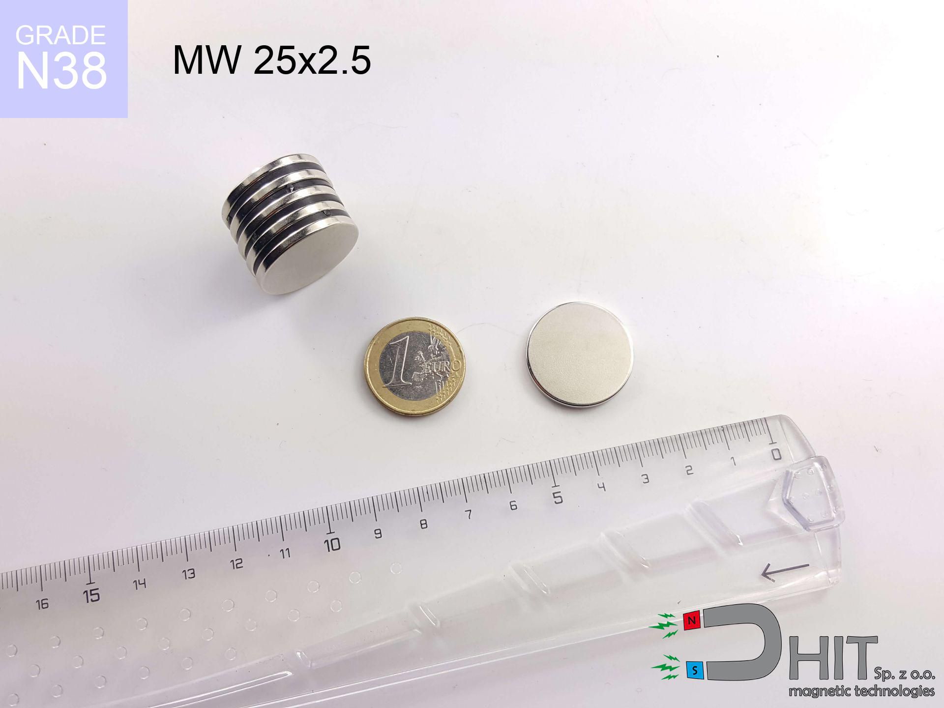
MW 25x2.5 / N38 - cylindrical magnet
cylindrical magnet
Catalog no 010449
GTIN/EAN: 5906301811121
Diameter Ø
25 mm [±0,1 mm]
Height
2.5 mm [±0,1 mm]
Weight
9.2 g
Magnetization Direction
↑ axial
Load capacity
2.55 kg / 25.03 N
Magnetic Induction
121.57 mT / 1216 Gs
Coating
[NiCuNi] Nickel
3.95 ZŁ with VAT / pcs + price for transport
3.21 ZŁ net + 23% VAT / pcs
bulk discounts:
Need more?
Give us a call
+48 22 499 98 98
or get in touch using
form
the contact page.
Lifting power along with form of magnets can be verified using our
online calculation tool.
Order by 14:00 and we’ll ship today!
Physical properties - MW 25x2.5 / N38 - cylindrical magnet
Specification / characteristics - MW 25x2.5 / N38 - cylindrical magnet
| properties | values |
|---|---|
| Cat. no. | 010449 |
| GTIN/EAN | 5906301811121 |
| Production/Distribution | Dhit sp. z o.o. |
| Country of origin | Poland / China / Germany |
| Customs code | 85059029 |
| Diameter Ø | 25 mm [±0,1 mm] |
| Height | 2.5 mm [±0,1 mm] |
| Weight | 9.2 g |
| Magnetization Direction | ↑ axial |
| Load capacity ~ ? | 2.55 kg / 25.03 N |
| Magnetic Induction ~ ? | 121.57 mT / 1216 Gs |
| Coating | [NiCuNi] Nickel |
| Manufacturing Tolerance | ±0.1 mm |
Magnetic properties of material N38
| properties | values | units |
|---|---|---|
| remenance Br [min. - max.] ? | 12.2-12.6 | kGs |
| remenance Br [min. - max.] ? | 1220-1260 | mT |
| coercivity bHc ? | 10.8-11.5 | kOe |
| coercivity bHc ? | 860-915 | kA/m |
| actual internal force iHc | ≥ 12 | kOe |
| actual internal force iHc | ≥ 955 | kA/m |
| energy density [min. - max.] ? | 36-38 | BH max MGOe |
| energy density [min. - max.] ? | 287-303 | BH max KJ/m |
| max. temperature ? | ≤ 80 | °C |
Physical properties of sintered neodymium magnets Nd2Fe14B at 20°C
| properties | values | units |
|---|---|---|
| Vickers hardness | ≥550 | Hv |
| Density | ≥7.4 | g/cm3 |
| Curie Temperature TC | 312 - 380 | °C |
| Curie Temperature TF | 593 - 716 | °F |
| Specific resistance | 150 | μΩ⋅cm |
| Bending strength | 250 | MPa |
| Compressive strength | 1000~1100 | MPa |
| Thermal expansion parallel (∥) to orientation (M) | (3-4) x 10-6 | °C-1 |
| Thermal expansion perpendicular (⊥) to orientation (M) | -(1-3) x 10-6 | °C-1 |
| Young's modulus | 1.7 x 10⁴ | kg/mm² |
Technical modeling of the product - report
Presented data are the result of a physical simulation. Results are based on models for the material Nd2Fe14B. Real-world conditions may deviate from the simulation results. Treat these calculations as a reference point when designing systems.
Table 1: Static force (pull vs distance) - power drop
MW 25x2.5 / N38
| Distance (mm) | Induction (Gauss) / mT | Pull Force (kg/lbs/g/N) | Risk Status |
|---|---|---|---|
| 0 mm |
1216 Gs
121.6 mT
|
2.55 kg / 5.62 lbs
2550.0 g / 25.0 N
|
medium risk |
| 1 mm |
1177 Gs
117.7 mT
|
2.39 kg / 5.27 lbs
2391.6 g / 23.5 N
|
medium risk |
| 2 mm |
1121 Gs
112.1 mT
|
2.17 kg / 4.78 lbs
2166.6 g / 21.3 N
|
medium risk |
| 3 mm |
1050 Gs
105.0 mT
|
1.90 kg / 4.19 lbs
1902.7 g / 18.7 N
|
safe |
| 5 mm |
887 Gs
88.7 mT
|
1.36 kg / 2.99 lbs
1358.4 g / 13.3 N
|
safe |
| 10 mm |
511 Gs
51.1 mT
|
0.45 kg / 0.99 lbs
450.5 g / 4.4 N
|
safe |
| 15 mm |
282 Gs
28.2 mT
|
0.14 kg / 0.30 lbs
137.4 g / 1.3 N
|
safe |
| 20 mm |
162 Gs
16.2 mT
|
0.05 kg / 0.10 lbs
45.4 g / 0.4 N
|
safe |
| 30 mm |
64 Gs
6.4 mT
|
0.01 kg / 0.02 lbs
7.0 g / 0.1 N
|
safe |
| 50 mm |
17 Gs
1.7 mT
|
0.00 kg / 0.00 lbs
0.5 g / 0.0 N
|
safe |
Table 2: Shear force (wall)
MW 25x2.5 / N38
| Distance (mm) | Friction coefficient | Pull Force (kg/lbs/g/N) |
|---|---|---|
| 0 mm | Stal (~0.2) |
0.51 kg / 1.12 lbs
510.0 g / 5.0 N
|
| 1 mm | Stal (~0.2) |
0.48 kg / 1.05 lbs
478.0 g / 4.7 N
|
| 2 mm | Stal (~0.2) |
0.43 kg / 0.96 lbs
434.0 g / 4.3 N
|
| 3 mm | Stal (~0.2) |
0.38 kg / 0.84 lbs
380.0 g / 3.7 N
|
| 5 mm | Stal (~0.2) |
0.27 kg / 0.60 lbs
272.0 g / 2.7 N
|
| 10 mm | Stal (~0.2) |
0.09 kg / 0.20 lbs
90.0 g / 0.9 N
|
| 15 mm | Stal (~0.2) |
0.03 kg / 0.06 lbs
28.0 g / 0.3 N
|
| 20 mm | Stal (~0.2) |
0.01 kg / 0.02 lbs
10.0 g / 0.1 N
|
| 30 mm | Stal (~0.2) |
0.00 kg / 0.00 lbs
2.0 g / 0.0 N
|
| 50 mm | Stal (~0.2) |
0.00 kg / 0.00 lbs
0.0 g / 0.0 N
|
Table 3: Wall mounting (shearing) - behavior on slippery surfaces
MW 25x2.5 / N38
| Surface type | Friction coefficient / % Mocy | Max load (kg/lbs/g/N) |
|---|---|---|
| Raw steel |
µ = 0.3
30% Nominalnej Siły
|
0.76 kg / 1.69 lbs
765.0 g / 7.5 N
|
| Painted steel (standard) |
µ = 0.2
20% Nominalnej Siły
|
0.51 kg / 1.12 lbs
510.0 g / 5.0 N
|
| Oily/slippery steel |
µ = 0.1
10% Nominalnej Siły
|
0.26 kg / 0.56 lbs
255.0 g / 2.5 N
|
| Magnet with anti-slip rubber |
µ = 0.5
50% Nominalnej Siły
|
1.28 kg / 2.81 lbs
1275.0 g / 12.5 N
|
Table 4: Material efficiency (substrate influence) - power losses
MW 25x2.5 / N38
| Steel thickness (mm) | % power | Real pull force (kg/lbs/g/N) |
|---|---|---|
| 0.5 mm |
|
0.26 kg / 0.56 lbs
255.0 g / 2.5 N
|
| 1 mm |
|
0.64 kg / 1.41 lbs
637.5 g / 6.3 N
|
| 2 mm |
|
1.28 kg / 2.81 lbs
1275.0 g / 12.5 N
|
| 3 mm |
|
1.91 kg / 4.22 lbs
1912.5 g / 18.8 N
|
| 5 mm |
|
2.55 kg / 5.62 lbs
2550.0 g / 25.0 N
|
| 10 mm |
|
2.55 kg / 5.62 lbs
2550.0 g / 25.0 N
|
| 11 mm |
|
2.55 kg / 5.62 lbs
2550.0 g / 25.0 N
|
| 12 mm |
|
2.55 kg / 5.62 lbs
2550.0 g / 25.0 N
|
Table 5: Thermal resistance (material behavior) - power drop
MW 25x2.5 / N38
| Ambient temp. (°C) | Power loss | Remaining pull (kg/lbs/g/N) | Status |
|---|---|---|---|
| 20 °C | 0.0% |
2.55 kg / 5.62 lbs
2550.0 g / 25.0 N
|
OK |
| 40 °C | -2.2% |
2.49 kg / 5.50 lbs
2493.9 g / 24.5 N
|
OK |
| 60 °C | -4.4% |
2.44 kg / 5.37 lbs
2437.8 g / 23.9 N
|
|
| 80 °C | -6.6% |
2.38 kg / 5.25 lbs
2381.7 g / 23.4 N
|
|
| 100 °C | -28.8% |
1.82 kg / 4.00 lbs
1815.6 g / 17.8 N
|
Table 6: Two magnets (attraction) - field collision
MW 25x2.5 / N38
| Gap (mm) | Attraction (kg/lbs) (N-S) | Sliding Force (kg/lbs/g/N) | Repulsion (kg/lbs) (N-N) |
|---|---|---|---|
| 0 mm |
4.47 kg / 9.86 lbs
2 302 Gs
|
0.67 kg / 1.48 lbs
671 g / 6.6 N
|
N/A |
| 1 mm |
4.35 kg / 9.59 lbs
2 398 Gs
|
0.65 kg / 1.44 lbs
653 g / 6.4 N
|
3.92 kg / 8.63 lbs
~0 Gs
|
| 2 mm |
4.19 kg / 9.25 lbs
2 355 Gs
|
0.63 kg / 1.39 lbs
629 g / 6.2 N
|
3.77 kg / 8.32 lbs
~0 Gs
|
| 3 mm |
4.01 kg / 8.84 lbs
2 302 Gs
|
0.60 kg / 1.33 lbs
601 g / 5.9 N
|
3.61 kg / 7.95 lbs
~0 Gs
|
| 5 mm |
3.57 kg / 7.88 lbs
2 173 Gs
|
0.54 kg / 1.18 lbs
536 g / 5.3 N
|
3.22 kg / 7.09 lbs
~0 Gs
|
| 10 mm |
2.38 kg / 5.25 lbs
1 775 Gs
|
0.36 kg / 0.79 lbs
357 g / 3.5 N
|
2.14 kg / 4.73 lbs
~0 Gs
|
| 20 mm |
0.79 kg / 1.74 lbs
1 022 Gs
|
0.12 kg / 0.26 lbs
119 g / 1.2 N
|
0.71 kg / 1.57 lbs
~0 Gs
|
| 50 mm |
0.03 kg / 0.07 lbs
198 Gs
|
0.00 kg / 0.01 lbs
4 g / 0.0 N
|
0.03 kg / 0.06 lbs
~0 Gs
|
| 60 mm |
0.01 kg / 0.03 lbs
127 Gs
|
0.00 kg / 0.00 lbs
2 g / 0.0 N
|
0.01 kg / 0.02 lbs
~0 Gs
|
| 70 mm |
0.01 kg / 0.01 lbs
86 Gs
|
0.00 kg / 0.00 lbs
1 g / 0.0 N
|
0.00 kg / 0.00 lbs
~0 Gs
|
| 80 mm |
0.00 kg / 0.01 lbs
61 Gs
|
0.00 kg / 0.00 lbs
0 g / 0.0 N
|
0.00 kg / 0.00 lbs
~0 Gs
|
| 90 mm |
0.00 kg / 0.00 lbs
44 Gs
|
0.00 kg / 0.00 lbs
0 g / 0.0 N
|
0.00 kg / 0.00 lbs
~0 Gs
|
| 100 mm |
0.00 kg / 0.00 lbs
33 Gs
|
0.00 kg / 0.00 lbs
0 g / 0.0 N
|
0.00 kg / 0.00 lbs
~0 Gs
|
Table 7: Safety (HSE) (electronics) - precautionary measures
MW 25x2.5 / N38
| Object / Device | Limit (Gauss) / mT | Safe distance |
|---|---|---|
| Pacemaker | 5 Gs (0.5 mT) | 8.0 cm |
| Hearing aid | 10 Gs (1.0 mT) | 6.0 cm |
| Mechanical watch | 20 Gs (2.0 mT) | 5.0 cm |
| Mobile device | 40 Gs (4.0 mT) | 4.0 cm |
| Car key | 50 Gs (5.0 mT) | 3.5 cm |
| Payment card | 400 Gs (40.0 mT) | 1.5 cm |
| HDD hard drive | 600 Gs (60.0 mT) | 1.0 cm |
Table 8: Dynamics (kinetic energy) - warning
MW 25x2.5 / N38
| Start from (mm) | Speed (km/h) | Energy (J) | Predicted outcome |
|---|---|---|---|
| 10 mm |
18.55 km/h
(5.15 m/s)
|
0.12 J | |
| 30 mm |
29.13 km/h
(8.09 m/s)
|
0.30 J | |
| 50 mm |
37.55 km/h
(10.43 m/s)
|
0.50 J | |
| 100 mm |
53.10 km/h
(14.75 m/s)
|
1.00 J |
Table 9: Surface protection spec
MW 25x2.5 / N38
| Technical parameter | Value / Description |
|---|---|
| Coating type | [NiCuNi] Nickel |
| Layer structure | Nickel - Copper - Nickel |
| Layer thickness | 10-20 µm |
| Salt spray test (SST) ? | 24 h |
| Recommended environment | Indoors only (dry) |
Table 10: Construction data (Flux)
MW 25x2.5 / N38
| Parameter | Value | SI Unit / Description |
|---|---|---|
| Magnetic Flux | 7 872 Mx | 78.7 µWb |
| Pc Coefficient | 0.16 | Low (Flat) |
Table 11: Underwater work (magnet fishing)
MW 25x2.5 / N38
| Environment | Effective steel pull | Effect |
|---|---|---|
| Air (land) | 2.55 kg | Standard |
| Water (riverbed) |
2.92 kg
(+0.37 kg buoyancy gain)
|
+14.5% |
1. Shear force
*Warning: On a vertical wall, the magnet retains merely approx. 20-30% of its nominal pull.
2. Plate thickness effect
*Thin steel (e.g. 0.5mm PC case) drastically limits the holding force.
3. Temperature resistance
*For N38 material, the critical limit is 80°C.
4. Demagnetization curve and operating point (B-H)
chart generated for the permeance coefficient Pc (Permeance Coefficient) = 0.16
The chart above illustrates the magnetic characteristics of the material within the second quadrant of the hysteresis loop. The solid red line represents the demagnetization curve (material potential), while the dashed blue line is the load line based on the magnet's geometry. The Pc (Permeance Coefficient), also known as the load line slope, is a dimensionless value that describes the relationship between the magnet's shape and its magnetic stability. The intersection of these two lines (the black dot) is the operating point — it determines the actual magnetic flux density generated by the magnet in this specific configuration. A higher Pc value means the magnet is more 'slender' (tall relative to its area), resulting in a higher operating point and better resistance to irreversible demagnetization caused by external fields or temperature. A value of 0.42 is relatively low (typical for flat magnets), meaning the operating point is closer to the 'knee' of the curve — caution is advised when operating at temperatures near the maximum limit to avoid strength loss.
Chemical composition
| iron (Fe) | 64% – 68% |
| neodymium (Nd) | 29% – 32% |
| boron (B) | 1.1% – 1.2% |
| dysprosium (Dy) | 0.5% – 2.0% |
| coating (Ni-Cu-Ni) | < 0.05% |
Sustainability
| recyclability (EoL) | 100% |
| recycled raw materials | ~10% (pre-cons) |
| carbon footprint | low / zredukowany |
| waste code (EWC) | 16 02 16 |
See more offers


Pros and cons of Nd2Fe14B magnets.
Pros
- They do not lose strength, even during approximately ten years – the reduction in strength is only ~1% (according to tests),
- They feature excellent resistance to magnetism drop as a result of external magnetic sources,
- The use of an shiny finish of noble metals (nickel, gold, silver) causes the element to be more visually attractive,
- They feature high magnetic induction at the operating surface, making them more effective,
- Neodymium magnets are characterized by very high magnetic induction on the magnet surface and are able to act (depending on the shape) even at a temperature of 230°C or more...
- Possibility of individual forming as well as modifying to complex needs,
- Wide application in future technologies – they serve a role in magnetic memories, motor assemblies, precision medical tools, also multitasking production systems.
- Relatively small size with high pulling force – neodymium magnets offer impressive pulling force in tiny dimensions, which allows their use in miniature devices
Cons
- To avoid cracks upon strong impacts, we recommend using special steel holders. Such a solution secures the magnet and simultaneously increases its durability.
- Neodymium magnets decrease their force under the influence of heating. As soon as 80°C is exceeded, many of them start losing their force. Therefore, we recommend our special magnets marked [AH], which maintain stability even at temperatures up to 230°C
- Magnets exposed to a humid environment can rust. Therefore while using outdoors, we recommend using water-impermeable magnets made of rubber, plastic or other material resistant to moisture
- We suggest casing - magnetic mechanism, due to difficulties in creating threads inside the magnet and complicated forms.
- Potential hazard resulting from small fragments of magnets pose a threat, when accidentally swallowed, which becomes key in the context of child safety. It is also worth noting that small elements of these magnets are able to complicate diagnosis medical in case of swallowing.
- With mass production the cost of neodymium magnets is economically unviable,
Holding force characteristics
Optimal lifting capacity of a neodymium magnet – what contributes to it?
- using a base made of high-permeability steel, functioning as a ideal flux conductor
- possessing a thickness of min. 10 mm to avoid saturation
- with a plane free of scratches
- under conditions of ideal adhesion (surface-to-surface)
- during detachment in a direction vertical to the plane
- at conditions approx. 20°C
Lifting capacity in real conditions – factors
- Distance (betwixt the magnet and the metal), since even a very small clearance (e.g. 0.5 mm) leads to a drastic drop in force by up to 50% (this also applies to paint, rust or debris).
- Force direction – declared lifting capacity refers to pulling vertically. When attempting to slide, the magnet holds significantly lower power (typically approx. 20-30% of maximum force).
- Plate thickness – insufficiently thick steel does not accept the full field, causing part of the flux to be escaped into the air.
- Steel grade – ideal substrate is pure iron steel. Stainless steels may have worse magnetic properties.
- Plate texture – smooth surfaces ensure maximum contact, which improves field saturation. Rough surfaces reduce efficiency.
- Heat – NdFeB sinters have a negative temperature coefficient. At higher temperatures they lose power, and at low temperatures they can be stronger (up to a certain limit).
Holding force was checked on the plate surface of 20 mm thickness, when a perpendicular force was applied, in contrast under attempts to slide the magnet the holding force is lower. Additionally, even a minimal clearance between the magnet and the plate reduces the lifting capacity.
Safety rules for work with NdFeB magnets
Bodily injuries
Mind your fingers. Two large magnets will join immediately with a force of massive weight, destroying anything in their path. Be careful!
Magnet fragility
Protect your eyes. Magnets can fracture upon uncontrolled impact, ejecting shards into the air. We recommend safety glasses.
GPS Danger
Be aware: neodymium magnets generate a field that interferes with precision electronics. Maintain a safe distance from your mobile, device, and navigation systems.
Health Danger
For implant holders: Powerful magnets affect electronics. Maintain at least 30 cm distance or request help to work with the magnets.
Flammability
Powder produced during cutting of magnets is flammable. Avoid drilling into magnets unless you are an expert.
Electronic devices
Very strong magnetic fields can erase data on payment cards, HDDs, and storage devices. Maintain a gap of at least 10 cm.
Handling guide
Before starting, read the rules. Sudden snapping can break the magnet or hurt your hand. Be predictive.
Heat warning
Control the heat. Exposing the magnet to high heat will destroy its magnetic structure and strength.
Nickel coating and allergies
It is widely known that the nickel plating (standard magnet coating) is a common allergen. If your skin reacts to metals, avoid touching magnets with bare hands and opt for encased magnets.
Product not for children
Absolutely keep magnets out of reach of children. Risk of swallowing is significant, and the effects of magnets connecting inside the body are life-threatening.
Tabela kosztu i czasu dostawy
Płatność przed wysyłką:

GLS kurier
Przesyłka będzie u Ciebie za 2-3 dni
14.99 ZŁ

InPost Paczkomaty 24/7
Przesyłka będzie u Ciebie za 1-2 dni
12.30 ZŁ
Płatność przy odbiorze (pobranie):
GLS kurier
Przesyłka będzie u Ciebie za 1-2 dni
23.00 ZŁ
Rate the product
Your rating