

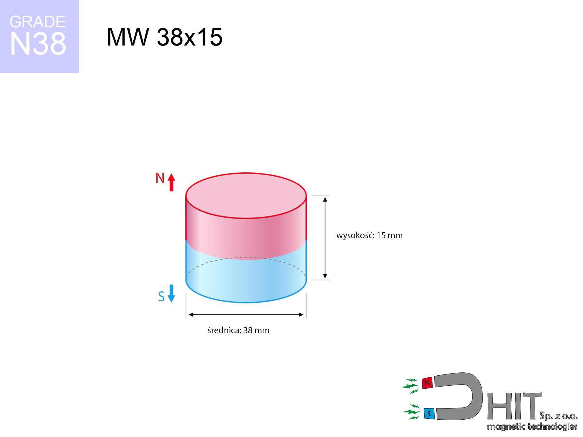
MW 38x15 / N38 - cylindrical magnet
cylindrical magnet
Catalog no 010061
GTIN/EAN: 5906301810605
Diameter Ø
38 mm [±0,1 mm]
Height
15 mm [±0,1 mm]
Weight
127.59 g
Magnetization Direction
↑ axial
Load capacity
40.08 kg / 393.18 N
Magnetic Induction
384.07 mT / 3841 Gs
Coating
[NiCuNi] Nickel
70.00 ZŁ with VAT / pcs + price for transport
56.91 ZŁ net + 23% VAT / pcs
bulk discounts:
Need more?
Pick up the phone and ask
+48 22 499 98 98
or let us know via
our online form
our website.
Parameters and form of a neodymium magnet can be analyzed on our
modular calculator.
Order by 14:00 and we’ll ship today!
Technical data of the product - MW 38x15 / N38 - cylindrical magnet
Specification / characteristics - MW 38x15 / N38 - cylindrical magnet
| properties | values |
|---|---|
| Cat. no. | 010061 |
| GTIN/EAN | 5906301810605 |
| Production/Distribution | Dhit sp. z o.o. |
| Country of origin | Poland / China / Germany |
| Customs code | 85059029 |
| Diameter Ø | 38 mm [±0,1 mm] |
| Height | 15 mm [±0,1 mm] |
| Weight | 127.59 g |
| Magnetization Direction | ↑ axial |
| Load capacity ~ ? | 40.08 kg / 393.18 N |
| Magnetic Induction ~ ? | 384.07 mT / 3841 Gs |
| Coating | [NiCuNi] Nickel |
| Manufacturing Tolerance | ±0.1 mm |
Magnetic properties of material N38
| properties | values | units |
|---|---|---|
| remenance Br [min. - max.] ? | 12.2-12.6 | kGs |
| remenance Br [min. - max.] ? | 1220-1260 | mT |
| coercivity bHc ? | 10.8-11.5 | kOe |
| coercivity bHc ? | 860-915 | kA/m |
| actual internal force iHc | ≥ 12 | kOe |
| actual internal force iHc | ≥ 955 | kA/m |
| energy density [min. - max.] ? | 36-38 | BH max MGOe |
| energy density [min. - max.] ? | 287-303 | BH max KJ/m |
| max. temperature ? | ≤ 80 | °C |
Physical properties of sintered neodymium magnets Nd2Fe14B at 20°C
| properties | values | units |
|---|---|---|
| Vickers hardness | ≥550 | Hv |
| Density | ≥7.4 | g/cm3 |
| Curie Temperature TC | 312 - 380 | °C |
| Curie Temperature TF | 593 - 716 | °F |
| Specific resistance | 150 | μΩ⋅cm |
| Bending strength | 250 | MPa |
| Compressive strength | 1000~1100 | MPa |
| Thermal expansion parallel (∥) to orientation (M) | (3-4) x 10-6 | °C-1 |
| Thermal expansion perpendicular (⊥) to orientation (M) | -(1-3) x 10-6 | °C-1 |
| Young's modulus | 1.7 x 10⁴ | kg/mm² |
Engineering analysis of the product - report
The following information are the result of a physical analysis. Results were calculated on algorithms for the class Nd2Fe14B. Operational parameters might slightly deviate from the simulation results. Use these data as a preliminary roadmap during assembly planning.
Table 1: Static force (force vs distance) - interaction chart
MW 38x15 / N38
| Distance (mm) | Induction (Gauss) / mT | Pull Force (kg/lbs/g/N) | Risk Status |
|---|---|---|---|
| 0 mm |
3840 Gs
384.0 mT
|
40.08 kg / 88.36 lbs
40080.0 g / 393.2 N
|
dangerous! |
| 1 mm |
3668 Gs
366.8 mT
|
36.56 kg / 80.61 lbs
36563.4 g / 358.7 N
|
dangerous! |
| 2 mm |
3485 Gs
348.5 mT
|
33.01 kg / 72.78 lbs
33011.6 g / 323.8 N
|
dangerous! |
| 3 mm |
3297 Gs
329.7 mT
|
29.55 kg / 65.14 lbs
29545.5 g / 289.8 N
|
dangerous! |
| 5 mm |
2917 Gs
291.7 mT
|
23.13 kg / 50.99 lbs
23128.9 g / 226.9 N
|
dangerous! |
| 10 mm |
2049 Gs
204.9 mT
|
11.41 kg / 25.15 lbs
11406.3 g / 111.9 N
|
dangerous! |
| 15 mm |
1396 Gs
139.6 mT
|
5.30 kg / 11.68 lbs
5297.4 g / 52.0 N
|
warning |
| 20 mm |
954 Gs
95.4 mT
|
2.47 kg / 5.45 lbs
2473.1 g / 24.3 N
|
warning |
| 30 mm |
474 Gs
47.4 mT
|
0.61 kg / 1.35 lbs
610.3 g / 6.0 N
|
weak grip |
| 50 mm |
155 Gs
15.5 mT
|
0.07 kg / 0.14 lbs
65.6 g / 0.6 N
|
weak grip |
Table 2: Vertical load (vertical surface)
MW 38x15 / N38
| Distance (mm) | Friction coefficient | Pull Force (kg/lbs/g/N) |
|---|---|---|
| 0 mm | Stal (~0.2) |
8.02 kg / 17.67 lbs
8016.0 g / 78.6 N
|
| 1 mm | Stal (~0.2) |
7.31 kg / 16.12 lbs
7312.0 g / 71.7 N
|
| 2 mm | Stal (~0.2) |
6.60 kg / 14.55 lbs
6602.0 g / 64.8 N
|
| 3 mm | Stal (~0.2) |
5.91 kg / 13.03 lbs
5910.0 g / 58.0 N
|
| 5 mm | Stal (~0.2) |
4.63 kg / 10.20 lbs
4626.0 g / 45.4 N
|
| 10 mm | Stal (~0.2) |
2.28 kg / 5.03 lbs
2282.0 g / 22.4 N
|
| 15 mm | Stal (~0.2) |
1.06 kg / 2.34 lbs
1060.0 g / 10.4 N
|
| 20 mm | Stal (~0.2) |
0.49 kg / 1.09 lbs
494.0 g / 4.8 N
|
| 30 mm | Stal (~0.2) |
0.12 kg / 0.27 lbs
122.0 g / 1.2 N
|
| 50 mm | Stal (~0.2) |
0.01 kg / 0.03 lbs
14.0 g / 0.1 N
|
Table 3: Wall mounting (sliding) - behavior on slippery surfaces
MW 38x15 / N38
| Surface type | Friction coefficient / % Mocy | Max load (kg/lbs/g/N) |
|---|---|---|
| Raw steel |
µ = 0.3
30% Nominalnej Siły
|
12.02 kg / 26.51 lbs
12024.0 g / 118.0 N
|
| Painted steel (standard) |
µ = 0.2
20% Nominalnej Siły
|
8.02 kg / 17.67 lbs
8016.0 g / 78.6 N
|
| Oily/slippery steel |
µ = 0.1
10% Nominalnej Siły
|
4.01 kg / 8.84 lbs
4008.0 g / 39.3 N
|
| Magnet with anti-slip rubber |
µ = 0.5
50% Nominalnej Siły
|
20.04 kg / 44.18 lbs
20040.0 g / 196.6 N
|
Table 4: Steel thickness (saturation) - power losses
MW 38x15 / N38
| Steel thickness (mm) | % power | Real pull force (kg/lbs/g/N) |
|---|---|---|
| 0.5 mm |
|
2.00 kg / 4.42 lbs
2004.0 g / 19.7 N
|
| 1 mm |
|
5.01 kg / 11.05 lbs
5010.0 g / 49.1 N
|
| 2 mm |
|
10.02 kg / 22.09 lbs
10020.0 g / 98.3 N
|
| 3 mm |
|
15.03 kg / 33.14 lbs
15030.0 g / 147.4 N
|
| 5 mm |
|
25.05 kg / 55.23 lbs
25050.0 g / 245.7 N
|
| 10 mm |
|
40.08 kg / 88.36 lbs
40080.0 g / 393.2 N
|
| 11 mm |
|
40.08 kg / 88.36 lbs
40080.0 g / 393.2 N
|
| 12 mm |
|
40.08 kg / 88.36 lbs
40080.0 g / 393.2 N
|
Table 5: Thermal resistance (material behavior) - resistance threshold
MW 38x15 / N38
| Ambient temp. (°C) | Power loss | Remaining pull (kg/lbs/g/N) | Status |
|---|---|---|---|
| 20 °C | 0.0% |
40.08 kg / 88.36 lbs
40080.0 g / 393.2 N
|
OK |
| 40 °C | -2.2% |
39.20 kg / 86.42 lbs
39198.2 g / 384.5 N
|
OK |
| 60 °C | -4.4% |
38.32 kg / 84.47 lbs
38316.5 g / 375.9 N
|
|
| 80 °C | -6.6% |
37.43 kg / 82.53 lbs
37434.7 g / 367.2 N
|
|
| 100 °C | -28.8% |
28.54 kg / 62.91 lbs
28537.0 g / 279.9 N
|
Table 6: Two magnets (repulsion) - field range
MW 38x15 / N38
| Gap (mm) | Attraction (kg/lbs) (N-S) | Shear Strength (kg/lbs/g/N) | Repulsion (kg/lbs) (N-N) |
|---|---|---|---|
| 0 mm |
103.10 kg / 227.31 lbs
5 235 Gs
|
15.47 kg / 34.10 lbs
15466 g / 151.7 N
|
N/A |
| 1 mm |
98.64 kg / 217.47 lbs
7 512 Gs
|
14.80 kg / 32.62 lbs
14796 g / 145.2 N
|
88.78 kg / 195.72 lbs
~0 Gs
|
| 2 mm |
94.06 kg / 207.36 lbs
7 336 Gs
|
14.11 kg / 31.10 lbs
14109 g / 138.4 N
|
84.65 kg / 186.63 lbs
~0 Gs
|
| 3 mm |
89.48 kg / 197.26 lbs
7 155 Gs
|
13.42 kg / 29.59 lbs
13421 g / 131.7 N
|
80.53 kg / 177.53 lbs
~0 Gs
|
| 5 mm |
80.42 kg / 177.30 lbs
6 783 Gs
|
12.06 kg / 26.60 lbs
12064 g / 118.3 N
|
72.38 kg / 159.57 lbs
~0 Gs
|
| 10 mm |
59.50 kg / 131.17 lbs
5 834 Gs
|
8.92 kg / 19.68 lbs
8925 g / 87.6 N
|
53.55 kg / 118.05 lbs
~0 Gs
|
| 20 mm |
29.34 kg / 64.69 lbs
4 097 Gs
|
4.40 kg / 9.70 lbs
4401 g / 43.2 N
|
26.41 kg / 58.22 lbs
~0 Gs
|
| 50 mm |
3.08 kg / 6.80 lbs
1 328 Gs
|
0.46 kg / 1.02 lbs
463 g / 4.5 N
|
2.78 kg / 6.12 lbs
~0 Gs
|
| 60 mm |
1.57 kg / 3.46 lbs
948 Gs
|
0.24 kg / 0.52 lbs
236 g / 2.3 N
|
1.41 kg / 3.12 lbs
~0 Gs
|
| 70 mm |
0.84 kg / 1.85 lbs
694 Gs
|
0.13 kg / 0.28 lbs
126 g / 1.2 N
|
0.76 kg / 1.67 lbs
~0 Gs
|
| 80 mm |
0.47 kg / 1.04 lbs
520 Gs
|
0.07 kg / 0.16 lbs
71 g / 0.7 N
|
0.42 kg / 0.94 lbs
~0 Gs
|
| 90 mm |
0.28 kg / 0.61 lbs
398 Gs
|
0.04 kg / 0.09 lbs
42 g / 0.4 N
|
0.25 kg / 0.55 lbs
~0 Gs
|
| 100 mm |
0.17 kg / 0.37 lbs
311 Gs
|
0.03 kg / 0.06 lbs
25 g / 0.2 N
|
0.15 kg / 0.33 lbs
~0 Gs
|
Table 7: Hazards (electronics) - warnings
MW 38x15 / N38
| Object / Device | Limit (Gauss) / mT | Safe distance |
|---|---|---|
| Pacemaker | 5 Gs (0.5 mT) | 18.5 cm |
| Hearing aid | 10 Gs (1.0 mT) | 14.5 cm |
| Timepiece | 20 Gs (2.0 mT) | 11.5 cm |
| Phone / Smartphone | 40 Gs (4.0 mT) | 9.0 cm |
| Car key | 50 Gs (5.0 mT) | 8.0 cm |
| Payment card | 400 Gs (40.0 mT) | 3.5 cm |
| HDD hard drive | 600 Gs (60.0 mT) | 3.0 cm |
Table 8: Collisions (kinetic energy) - warning
MW 38x15 / N38
| Start from (mm) | Speed (km/h) | Energy (J) | Predicted outcome |
|---|---|---|---|
| 10 mm |
20.81 km/h
(5.78 m/s)
|
2.13 J | |
| 30 mm |
31.25 km/h
(8.68 m/s)
|
4.81 J | |
| 50 mm |
40.01 km/h
(11.11 m/s)
|
7.88 J | |
| 100 mm |
56.53 km/h
(15.70 m/s)
|
15.73 J |
Table 9: Anti-corrosion coating durability
MW 38x15 / N38
| Technical parameter | Value / Description |
|---|---|
| Coating type | [NiCuNi] Nickel |
| Layer structure | Nickel - Copper - Nickel |
| Layer thickness | 10-20 µm |
| Salt spray test (SST) ? | 24 h |
| Recommended environment | Indoors only (dry) |
Table 10: Electrical data (Pc)
MW 38x15 / N38
| Parameter | Value | SI Unit / Description |
|---|---|---|
| Magnetic Flux | 45 065 Mx | 450.7 µWb |
| Pc Coefficient | 0.50 | Low (Flat) |
Table 11: Submerged application
MW 38x15 / N38
| Environment | Effective steel pull | Effect |
|---|---|---|
| Air (land) | 40.08 kg | Standard |
| Water (riverbed) |
45.89 kg
(+5.81 kg buoyancy gain)
|
+14.5% |
1. Sliding resistance
*Warning: On a vertical wall, the magnet holds just a fraction of its max power.
2. Steel saturation
*Thin metal sheet (e.g. computer case) significantly weakens the holding force.
3. Thermal stability
*For N38 material, the max working temp is 80°C.
4. Demagnetization curve and operating point (B-H)
chart generated for the permeance coefficient Pc (Permeance Coefficient) = 0.50
This simulation demonstrates the magnetic stability of the selected magnet under specific geometric conditions. The solid red line represents the demagnetization curve (material potential), while the dashed blue line is the load line based on the magnet's geometry. The Pc (Permeance Coefficient), also known as the load line slope, is a dimensionless value that describes the relationship between the magnet's shape and its magnetic stability. The intersection of these two lines (the black dot) is the operating point — it determines the actual magnetic flux density generated by the magnet in this specific configuration. A higher Pc value means the magnet is more 'slender' (tall relative to its area), resulting in a higher operating point and better resistance to irreversible demagnetization caused by external fields or temperature. A value of 0.42 is relatively low (typical for flat magnets), meaning the operating point is closer to the 'knee' of the curve — caution is advised when operating at temperatures near the maximum limit to avoid strength loss.
Chemical composition
| iron (Fe) | 64% – 68% |
| neodymium (Nd) | 29% – 32% |
| boron (B) | 1.1% – 1.2% |
| dysprosium (Dy) | 0.5% – 2.0% |
| coating (Ni-Cu-Ni) | < 0.05% |
Environmental data
| recyclability (EoL) | 100% |
| recycled raw materials | ~10% (pre-cons) |
| carbon footprint | low / zredukowany |
| waste code (EWC) | 16 02 16 |
Check out also products
![SM 25x325 [2xM8] / N42 - magnetic separator](https://cdn3.dhit.pl/graphics/products/sm-25x325-2xm8-man.jpg "SM 25x325 [2xM8] / N42 - magnetic separator")
![SM 32x350 [2xM8] / N52 - magnetic separator](https://cdn3.dhit.pl/graphics/products/sm-32x350-2xm8-fag.jpg "SM 32x350 [2xM8] / N52 - magnetic separator")


Pros and cons of rare earth magnets.
Benefits
- They virtually do not lose strength, because even after ten years the performance loss is only ~1% (according to literature),
- Magnets perfectly protect themselves against loss of magnetization caused by foreign field sources,
- In other words, due to the glossy surface of silver, the element becomes visually attractive,
- Magnets are characterized by exceptionally strong magnetic induction on the working surface,
- Made from properly selected components, these magnets show impressive resistance to high heat, enabling them to function (depending on their form) at temperatures up to 230°C and above...
- In view of the option of accurate forming and adaptation to unique needs, magnetic components can be produced in a variety of forms and dimensions, which increases their versatility,
- Huge importance in innovative solutions – they are used in hard drives, electric drive systems, diagnostic systems, also technologically advanced constructions.
- Thanks to efficiency per cm³, small magnets offer high operating force, in miniature format,
Disadvantages
- Susceptibility to cracking is one of their disadvantages. Upon strong impact they can break. We recommend keeping them in a steel housing, which not only protects them against impacts but also increases their durability
- We warn that neodymium magnets can reduce their strength at high temperatures. To prevent this, we recommend our specialized [AH] magnets, which work effectively even at 230°C.
- Due to the susceptibility of magnets to corrosion in a humid environment, we advise using waterproof magnets made of rubber, plastic or other material immune to moisture, when using outdoors
- We suggest casing - magnetic mechanism, due to difficulties in realizing threads inside the magnet and complicated forms.
- Potential hazard resulting from small fragments of magnets can be dangerous, in case of ingestion, which becomes key in the context of child health protection. Additionally, tiny parts of these devices are able to disrupt the diagnostic process medical in case of swallowing.
- With mass production the cost of neodymium magnets can be a barrier,
Lifting parameters
Highest magnetic holding force – what affects it?
- using a sheet made of low-carbon steel, serving as a ideal flux conductor
- with a cross-section minimum 10 mm
- characterized by smoothness
- with total lack of distance (no impurities)
- during detachment in a direction perpendicular to the plane
- at conditions approx. 20°C
Lifting capacity in real conditions – factors
- Gap (between the magnet and the plate), since even a microscopic distance (e.g. 0.5 mm) leads to a reduction in lifting capacity by up to 50% (this also applies to paint, rust or dirt).
- Force direction – note that the magnet has greatest strength perpendicularly. Under sliding down, the capacity drops drastically, often to levels of 20-30% of the maximum value.
- Plate thickness – too thin plate does not close the flux, causing part of the power to be lost to the other side.
- Steel type – mild steel gives the best results. Alloy admixtures reduce magnetic properties and lifting capacity.
- Surface quality – the more even the plate, the larger the contact zone and stronger the hold. Unevenness acts like micro-gaps.
- Temperature – heating the magnet results in weakening of induction. Check the maximum operating temperature for a given model.
Lifting capacity was measured with the use of a smooth steel plate of suitable thickness (min. 20 mm), under perpendicular pulling force, whereas under parallel forces the holding force is lower. Additionally, even a minimal clearance between the magnet and the plate lowers the lifting capacity.
Precautions when working with neodymium magnets
Do not overheat magnets
Keep cool. NdFeB magnets are sensitive to temperature. If you need resistance above 80°C, inquire about special high-temperature series (H, SH, UH).
Crushing risk
Protect your hands. Two large magnets will join instantly with a force of several hundred kilograms, crushing everything in their path. Be careful!
Handling guide
Handle magnets consciously. Their immense force can surprise even experienced users. Be vigilant and do not underestimate their force.
Keep away from children
These products are not intended for children. Accidental ingestion of a few magnets can lead to them attracting across intestines, which constitutes a severe health hazard and necessitates urgent medical intervention.
Danger to pacemakers
For implant holders: Powerful magnets disrupt medical devices. Keep at least 30 cm distance or request help to handle the magnets.
Dust explosion hazard
Combustion risk: Neodymium dust is highly flammable. Avoid machining magnets without safety gear as this risks ignition.
Impact on smartphones
Remember: rare earth magnets produce a field that interferes with precision electronics. Maintain a separation from your phone, device, and navigation systems.
Eye protection
Despite the nickel coating, the material is brittle and cannot withstand shocks. Do not hit, as the magnet may crumble into sharp, dangerous pieces.
Cards and drives
Equipment safety: Neodymium magnets can ruin payment cards and delicate electronics (pacemakers, hearing aids, mechanical watches).
Allergic reactions
Certain individuals have a sensitization to nickel, which is the standard coating for neodymium magnets. Extended handling may cause a rash. It is best to wear protective gloves.
Tabela kosztu i czasu dostawy
Płatność przed wysyłką:

GLS kurier
Przesyłka będzie u Ciebie za 2-3 dni
14.99 ZŁ

InPost Paczkomaty 24/7
Przesyłka będzie u Ciebie za 1-2 dni
12.30 ZŁ
Płatność przy odbiorze (pobranie):
GLS kurier
Przesyłka będzie u Ciebie za 1-2 dni
23.00 ZŁ
Rate the product
Your rating