
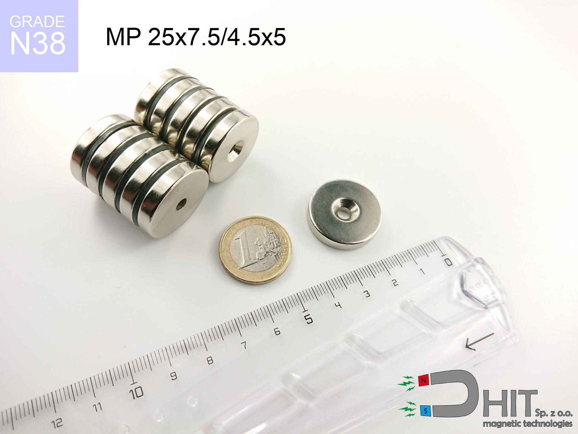
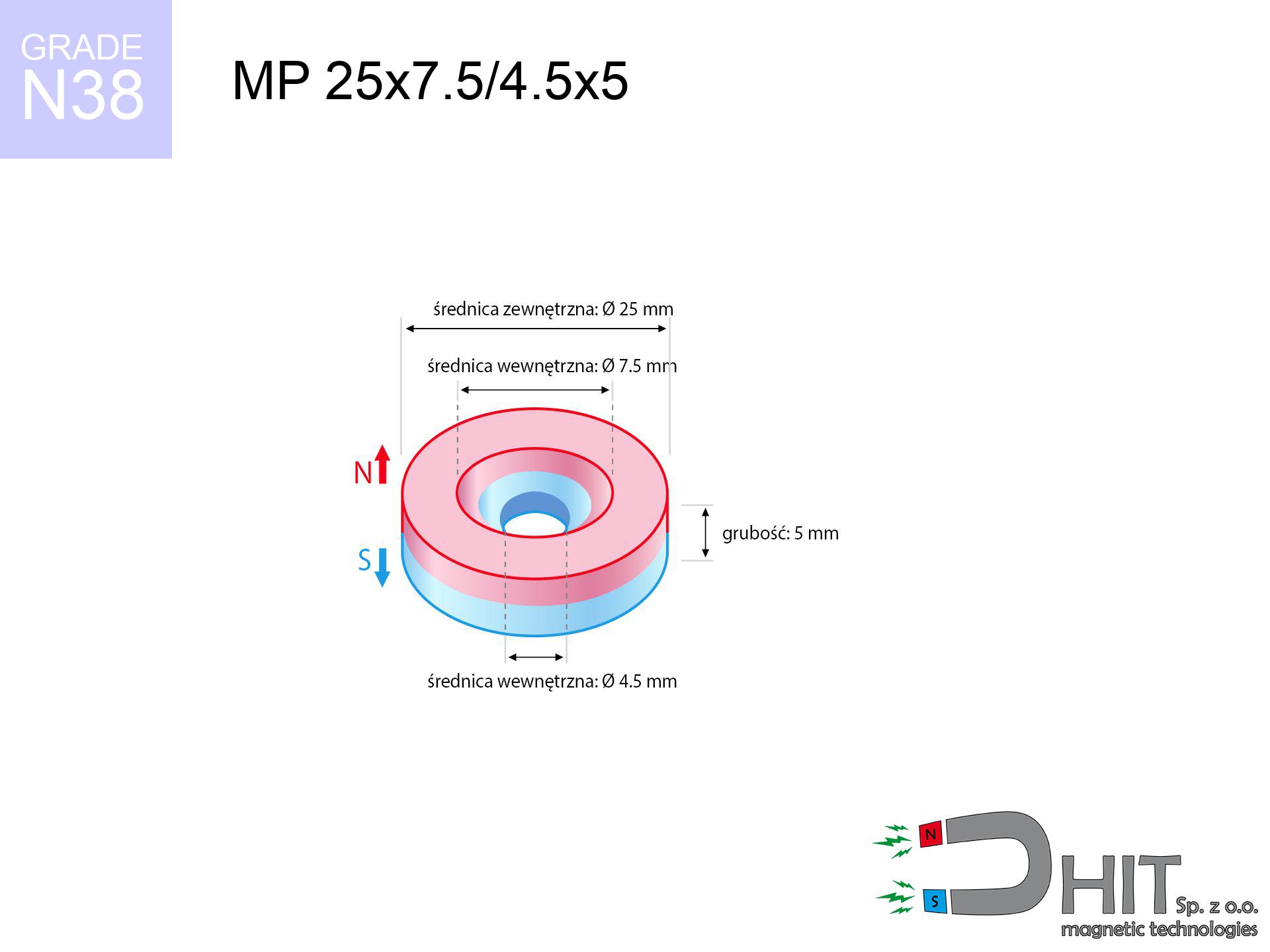
MP 25x7.5/4.5x5 / N38 - ring magnet
ring magnet
Catalog no 030194
GTIN/EAN: 5906301812111
Diameter
25 mm [±0,1 mm]
internal diameter Ø
7.5/4.5 mm [±0,1 mm]
Height
5 mm [±0,1 mm]
Weight
17.81 g
Magnetization Direction
↑ axial
Load capacity
7.72 kg / 75.69 N
Magnetic Induction
230.20 mT / 2302 Gs
Coating
[NiCuNi] Nickel
8.00 ZŁ with VAT / pcs + price for transport
6.50 ZŁ net + 23% VAT / pcs
bulk discounts:
Need more?
Contact us by phone
+48 888 99 98 98
if you prefer contact us by means of
request form
the contact form page.
Parameters along with form of magnetic components can be tested with our
force calculator.
Same-day processing for orders placed before 14:00.
Technical details - MP 25x7.5/4.5x5 / N38 - ring magnet
Specification / characteristics - MP 25x7.5/4.5x5 / N38 - ring magnet
| properties | values |
|---|---|
| Cat. no. | 030194 |
| GTIN/EAN | 5906301812111 |
| Production/Distribution | Dhit sp. z o.o. |
| Country of origin | Poland / China / Germany |
| Customs code | 85059029 |
| Diameter | 25 mm [±0,1 mm] |
| internal diameter Ø | 7.5/4.5 mm [±0,1 mm] |
| Height | 5 mm [±0,1 mm] |
| Weight | 17.81 g |
| Magnetization Direction | ↑ axial |
| Load capacity ~ ? | 7.72 kg / 75.69 N |
| Magnetic Induction ~ ? | 230.20 mT / 2302 Gs |
| Coating | [NiCuNi] Nickel |
| Manufacturing Tolerance | ±0.1 mm |
Magnetic properties of material N38
| properties | values | units |
|---|---|---|
| remenance Br [min. - max.] ? | 12.2-12.6 | kGs |
| remenance Br [min. - max.] ? | 1220-1260 | mT |
| coercivity bHc ? | 10.8-11.5 | kOe |
| coercivity bHc ? | 860-915 | kA/m |
| actual internal force iHc | ≥ 12 | kOe |
| actual internal force iHc | ≥ 955 | kA/m |
| energy density [min. - max.] ? | 36-38 | BH max MGOe |
| energy density [min. - max.] ? | 287-303 | BH max KJ/m |
| max. temperature ? | ≤ 80 | °C |
Physical properties of sintered neodymium magnets Nd2Fe14B at 20°C
| properties | values | units |
|---|---|---|
| Vickers hardness | ≥550 | Hv |
| Density | ≥7.4 | g/cm3 |
| Curie Temperature TC | 312 - 380 | °C |
| Curie Temperature TF | 593 - 716 | °F |
| Specific resistance | 150 | μΩ⋅cm |
| Bending strength | 250 | MPa |
| Compressive strength | 1000~1100 | MPa |
| Thermal expansion parallel (∥) to orientation (M) | (3-4) x 10-6 | °C-1 |
| Thermal expansion perpendicular (⊥) to orientation (M) | -(1-3) x 10-6 | °C-1 |
| Young's modulus | 1.7 x 10⁴ | kg/mm² |
Technical analysis of the magnet - technical parameters
These values represent the direct effect of a engineering simulation. Results are based on algorithms for the material Nd2Fe14B. Actual performance might slightly differ from theoretical values. Please consider these data as a preliminary roadmap when designing systems.
Table 1: Static force (force vs gap) - interaction chart
MP 25x7.5/4.5x5 / N38
| Distance (mm) | Induction (Gauss) / mT | Pull Force (kg/lbs/g/N) | Risk Status |
|---|---|---|---|
| 0 mm |
1995 Gs
199.5 mT
|
7.72 kg / 17.02 LBS
7720.0 g / 75.7 N
|
warning |
| 1 mm |
1906 Gs
190.6 mT
|
7.05 kg / 15.54 LBS
7049.4 g / 69.2 N
|
warning |
| 2 mm |
1793 Gs
179.3 mT
|
6.24 kg / 13.75 LBS
6236.8 g / 61.2 N
|
warning |
| 3 mm |
1664 Gs
166.4 mT
|
5.37 kg / 11.84 LBS
5368.9 g / 52.7 N
|
warning |
| 5 mm |
1385 Gs
138.5 mT
|
3.72 kg / 8.21 LBS
3722.8 g / 36.5 N
|
warning |
| 10 mm |
788 Gs
78.8 mT
|
1.20 kg / 2.65 LBS
1203.8 g / 11.8 N
|
safe |
| 15 mm |
437 Gs
43.7 mT
|
0.37 kg / 0.82 LBS
370.3 g / 3.6 N
|
safe |
| 20 mm |
253 Gs
25.3 mT
|
0.12 kg / 0.27 LBS
124.5 g / 1.2 N
|
safe |
| 30 mm |
101 Gs
10.1 mT
|
0.02 kg / 0.04 LBS
19.8 g / 0.2 N
|
safe |
| 50 mm |
27 Gs
2.7 mT
|
0.00 kg / 0.00 LBS
1.4 g / 0.0 N
|
safe |
Table 2: Vertical load (vertical surface)
MP 25x7.5/4.5x5 / N38
| Distance (mm) | Friction coefficient | Pull Force (kg/lbs/g/N) |
|---|---|---|
| 0 mm | Stal (~0.2) |
1.54 kg / 3.40 LBS
1544.0 g / 15.1 N
|
| 1 mm | Stal (~0.2) |
1.41 kg / 3.11 LBS
1410.0 g / 13.8 N
|
| 2 mm | Stal (~0.2) |
1.25 kg / 2.75 LBS
1248.0 g / 12.2 N
|
| 3 mm | Stal (~0.2) |
1.07 kg / 2.37 LBS
1074.0 g / 10.5 N
|
| 5 mm | Stal (~0.2) |
0.74 kg / 1.64 LBS
744.0 g / 7.3 N
|
| 10 mm | Stal (~0.2) |
0.24 kg / 0.53 LBS
240.0 g / 2.4 N
|
| 15 mm | Stal (~0.2) |
0.07 kg / 0.16 LBS
74.0 g / 0.7 N
|
| 20 mm | Stal (~0.2) |
0.02 kg / 0.05 LBS
24.0 g / 0.2 N
|
| 30 mm | Stal (~0.2) |
0.00 kg / 0.01 LBS
4.0 g / 0.0 N
|
| 50 mm | Stal (~0.2) |
0.00 kg / 0.00 LBS
0.0 g / 0.0 N
|
Table 3: Vertical assembly (shearing) - behavior on slippery surfaces
MP 25x7.5/4.5x5 / N38
| Surface type | Friction coefficient / % Mocy | Max load (kg/lbs/g/N) |
|---|---|---|
| Raw steel |
µ = 0.3
30% Nominalnej Siły
|
2.32 kg / 5.11 LBS
2316.0 g / 22.7 N
|
| Painted steel (standard) |
µ = 0.2
20% Nominalnej Siły
|
1.54 kg / 3.40 LBS
1544.0 g / 15.1 N
|
| Oily/slippery steel |
µ = 0.1
10% Nominalnej Siły
|
0.77 kg / 1.70 LBS
772.0 g / 7.6 N
|
| Magnet with anti-slip rubber |
µ = 0.5
50% Nominalnej Siły
|
3.86 kg / 8.51 LBS
3860.0 g / 37.9 N
|
Table 4: Steel thickness (saturation) - sheet metal selection
MP 25x7.5/4.5x5 / N38
| Steel thickness (mm) | % power | Real pull force (kg/lbs/g/N) |
|---|---|---|
| 0.5 mm |
|
0.77 kg / 1.70 LBS
772.0 g / 7.6 N
|
| 1 mm |
|
1.93 kg / 4.25 LBS
1930.0 g / 18.9 N
|
| 2 mm |
|
3.86 kg / 8.51 LBS
3860.0 g / 37.9 N
|
| 3 mm |
|
5.79 kg / 12.76 LBS
5790.0 g / 56.8 N
|
| 5 mm |
|
7.72 kg / 17.02 LBS
7720.0 g / 75.7 N
|
| 10 mm |
|
7.72 kg / 17.02 LBS
7720.0 g / 75.7 N
|
| 11 mm |
|
7.72 kg / 17.02 LBS
7720.0 g / 75.7 N
|
| 12 mm |
|
7.72 kg / 17.02 LBS
7720.0 g / 75.7 N
|
Table 5: Thermal resistance (stability) - power drop
MP 25x7.5/4.5x5 / N38
| Ambient temp. (°C) | Power loss | Remaining pull (kg/lbs/g/N) | Status |
|---|---|---|---|
| 20 °C | 0.0% |
7.72 kg / 17.02 LBS
7720.0 g / 75.7 N
|
OK |
| 40 °C | -2.2% |
7.55 kg / 16.65 LBS
7550.2 g / 74.1 N
|
OK |
| 60 °C | -4.4% |
7.38 kg / 16.27 LBS
7380.3 g / 72.4 N
|
|
| 80 °C | -6.6% |
7.21 kg / 15.90 LBS
7210.5 g / 70.7 N
|
|
| 100 °C | -28.8% |
5.50 kg / 12.12 LBS
5496.6 g / 53.9 N
|
Table 6: Two magnets (repulsion) - forces in the system
MP 25x7.5/4.5x5 / N38
| Gap (mm) | Attraction (kg/lbs) (N-S) | Sliding Force (kg/lbs/g/N) | Repulsion (kg/lbs) (N-N) |
|---|---|---|---|
| 0 mm |
9.91 kg / 21.84 LBS
3 484 Gs
|
1.49 kg / 3.28 LBS
1486 g / 14.6 N
|
N/A |
| 1 mm |
9.51 kg / 20.96 LBS
3 909 Gs
|
1.43 kg / 3.14 LBS
1426 g / 14.0 N
|
8.56 kg / 18.87 LBS
~0 Gs
|
| 2 mm |
9.05 kg / 19.94 LBS
3 813 Gs
|
1.36 kg / 2.99 LBS
1357 g / 13.3 N
|
8.14 kg / 17.95 LBS
~0 Gs
|
| 3 mm |
8.54 kg / 18.83 LBS
3 705 Gs
|
1.28 kg / 2.82 LBS
1281 g / 12.6 N
|
7.69 kg / 16.94 LBS
~0 Gs
|
| 5 mm |
7.45 kg / 16.42 LBS
3 460 Gs
|
1.12 kg / 2.46 LBS
1117 g / 11.0 N
|
6.70 kg / 14.78 LBS
~0 Gs
|
| 10 mm |
4.78 kg / 10.53 LBS
2 771 Gs
|
0.72 kg / 1.58 LBS
717 g / 7.0 N
|
4.30 kg / 9.48 LBS
~0 Gs
|
| 20 mm |
1.54 kg / 3.41 LBS
1 576 Gs
|
0.23 kg / 0.51 LBS
232 g / 2.3 N
|
1.39 kg / 3.06 LBS
~0 Gs
|
| 50 mm |
0.06 kg / 0.13 LBS
312 Gs
|
0.01 kg / 0.02 LBS
9 g / 0.1 N
|
0.05 kg / 0.12 LBS
~0 Gs
|
| 60 mm |
0.03 kg / 0.06 LBS
202 Gs
|
0.00 kg / 0.01 LBS
4 g / 0.0 N
|
0.02 kg / 0.05 LBS
~0 Gs
|
| 70 mm |
0.01 kg / 0.03 LBS
138 Gs
|
0.00 kg / 0.00 LBS
2 g / 0.0 N
|
0.01 kg / 0.02 LBS
~0 Gs
|
| 80 mm |
0.01 kg / 0.01 LBS
97 Gs
|
0.00 kg / 0.00 LBS
1 g / 0.0 N
|
0.00 kg / 0.00 LBS
~0 Gs
|
| 90 mm |
0.00 kg / 0.01 LBS
71 Gs
|
0.00 kg / 0.00 LBS
0 g / 0.0 N
|
0.00 kg / 0.00 LBS
~0 Gs
|
| 100 mm |
0.00 kg / 0.00 LBS
54 Gs
|
0.00 kg / 0.00 LBS
0 g / 0.0 N
|
0.00 kg / 0.00 LBS
~0 Gs
|
Table 7: Safety (HSE) (implants) - warnings
MP 25x7.5/4.5x5 / N38
| Object / Device | Limit (Gauss) / mT | Safe distance |
|---|---|---|
| Pacemaker | 5 Gs (0.5 mT) | 9.5 cm |
| Hearing aid | 10 Gs (1.0 mT) | 7.5 cm |
| Mechanical watch | 20 Gs (2.0 mT) | 6.0 cm |
| Mobile device | 40 Gs (4.0 mT) | 4.5 cm |
| Remote | 50 Gs (5.0 mT) | 4.0 cm |
| Payment card | 400 Gs (40.0 mT) | 2.0 cm |
| HDD hard drive | 600 Gs (60.0 mT) | 1.5 cm |
Table 8: Impact energy (kinetic energy) - collision effects
MP 25x7.5/4.5x5 / N38
| Start from (mm) | Speed (km/h) | Energy (J) | Predicted outcome |
|---|---|---|---|
| 10 mm |
22.95 km/h
(6.38 m/s)
|
0.36 J | |
| 30 mm |
36.43 km/h
(10.12 m/s)
|
0.91 J | |
| 50 mm |
46.96 km/h
(13.04 m/s)
|
1.52 J | |
| 100 mm |
66.40 km/h
(18.44 m/s)
|
3.03 J |
Table 9: Anti-corrosion coating durability
MP 25x7.5/4.5x5 / N38
| Technical parameter | Value / Description |
|---|---|
| Coating type | [NiCuNi] Nickel |
| Layer structure | Nickel - Copper - Nickel |
| Layer thickness | 10-20 µm |
| Salt spray test (SST) ? | 24 h |
| Recommended environment | Indoors only (dry) |
Table 10: Construction data (Pc)
MP 25x7.5/4.5x5 / N38
| Parameter | Value | SI Unit / Description |
|---|---|---|
| Magnetic Flux | 9 759 Mx | 97.6 µWb |
| Pc Coefficient | 0.25 | Low (Flat) |
Table 11: Submerged application
MP 25x7.5/4.5x5 / N38
| Environment | Effective steel pull | Effect |
|---|---|---|
| Air (land) | 7.72 kg | Standard |
| Water (riverbed) |
8.84 kg
(+1.12 kg buoyancy gain)
|
+14.5% |
1. Sliding resistance
*Note: On a vertical wall, the magnet retains only approx. 20-30% of its max power.
2. Steel saturation
*Thin metal sheet (e.g. computer case) severely weakens the holding force.
3. Temperature resistance
*For N38 grade, the safety limit is 80°C.
4. Demagnetization curve and operating point (B-H)
chart generated for the permeance coefficient Pc (Permeance Coefficient) = 0.25
The chart above illustrates the magnetic characteristics of the material within the second quadrant of the hysteresis loop. The solid red line represents the demagnetization curve (material potential), while the dashed blue line is the load line based on the magnet's geometry. The Pc (Permeance Coefficient), also known as the load line slope, is a dimensionless value that describes the relationship between the magnet's shape and its magnetic stability. The intersection of these two lines (the black dot) is the operating point — it determines the actual magnetic flux density generated by the magnet in this specific configuration. A higher Pc value means the magnet is more 'slender' (tall relative to its area), resulting in a higher operating point and better resistance to irreversible demagnetization caused by external fields or temperature. A value of 0.42 is relatively low (typical for flat magnets), meaning the operating point is closer to the 'knee' of the curve — caution is advised when operating at temperatures near the maximum limit to avoid strength loss.
Chemical composition
| iron (Fe) | 64% – 68% |
| neodymium (Nd) | 29% – 32% |
| boron (B) | 1.1% – 1.2% |
| dysprosium (Dy) | 0.5% – 2.0% |
| coating (Ni-Cu-Ni) | < 0.05% |
Environmental data
| recyclability (EoL) | 100% |
| recycled raw materials | ~10% (pre-cons) |
| carbon footprint | low / zredukowany |
| waste code (EWC) | 16 02 16 |
See more deals
![UMGZ 25x17x8 [M5] GZ / N38 - magnetic holder external thread](https://cdn3.dhit.pl/graphics/products/um-25x17x8-m5-gz-keb.jpg "UMGZ 25x17x8 [M5] GZ / N38 - magnetic holder external thread")

![UMP 135x40 [M10+M12] GW F 600 kg / N38 - search holder](https://cdn3.dhit.pl/graphics/products/ump135x40-m10+m12-gw-f-600-kg-luz.jpg "UMP 135x40 [M10+M12] GW F 600 kg / N38 - search holder")

Advantages and disadvantages of neodymium magnets.
Pros
- They have stable power, and over nearly 10 years their performance decreases symbolically – ~1% (according to theory),
- They feature excellent resistance to weakening of magnetic properties when exposed to opposing magnetic fields,
- By using a smooth coating of silver, the element presents an proper look,
- Neodymium magnets achieve maximum magnetic induction on a their surface, which allows for strong attraction,
- Thanks to resistance to high temperature, they can operate (depending on the shape) even at temperatures up to 230°C and higher...
- Possibility of accurate machining and adapting to atypical applications,
- Wide application in future technologies – they find application in hard drives, motor assemblies, advanced medical instruments, and modern systems.
- Thanks to concentrated force, small magnets offer high operating force, occupying minimum space,
Weaknesses
- Susceptibility to cracking is one of their disadvantages. Upon strong impact they can break. We recommend keeping them in a special holder, which not only protects them against impacts but also increases their durability
- Neodymium magnets lose power when exposed to high temperatures. After reaching 80°C, many of them experience permanent drop of power (a factor is the shape as well as dimensions of the magnet). We offer magnets specially adapted to work at temperatures up to 230°C marked [AH], which are extremely resistant to heat
- They rust in a humid environment - during use outdoors we recommend using waterproof magnets e.g. in rubber, plastic
- Limited ability of creating threads in the magnet and complex forms - recommended is cover - mounting mechanism.
- Potential hazard related to microscopic parts of magnets pose a threat, in case of ingestion, which gains importance in the context of child safety. Additionally, tiny parts of these products are able to disrupt the diagnostic process medical when they are in the body.
- Higher cost of purchase is one of the disadvantages compared to ceramic magnets, especially in budget applications
Pull force analysis
Maximum magnetic pulling force – what contributes to it?
- on a block made of mild steel, perfectly concentrating the magnetic field
- possessing a massiveness of at least 10 mm to avoid saturation
- with a surface free of scratches
- under conditions of ideal adhesion (surface-to-surface)
- during pulling in a direction perpendicular to the plane
- in stable room temperature
Determinants of practical lifting force of a magnet
- Distance (between the magnet and the metal), because even a tiny clearance (e.g. 0.5 mm) results in a drastic drop in lifting capacity by up to 50% (this also applies to paint, corrosion or debris).
- Loading method – declared lifting capacity refers to detachment vertically. When slipping, the magnet exhibits significantly lower power (often approx. 20-30% of maximum force).
- Wall thickness – thin material does not allow full use of the magnet. Magnetic flux passes through the material instead of generating force.
- Plate material – mild steel attracts best. Alloy admixtures decrease magnetic permeability and lifting capacity.
- Surface structure – the more even the plate, the larger the contact zone and higher the lifting capacity. Roughness creates an air distance.
- Operating temperature – neodymium magnets have a sensitivity to temperature. At higher temperatures they lose power, and at low temperatures gain strength (up to a certain limit).
Holding force was tested on a smooth steel plate of 20 mm thickness, when the force acted perpendicularly, whereas under parallel forces the holding force is lower. In addition, even a small distance between the magnet and the plate lowers the load capacity.
Warnings
Health Danger
Individuals with a ICD should maintain an large gap from magnets. The magnetic field can interfere with the functioning of the implant.
Shattering risk
Neodymium magnets are sintered ceramics, meaning they are fragile like glass. Clashing of two magnets leads to them breaking into shards.
No play value
Only for adults. Tiny parts can be swallowed, leading to intestinal necrosis. Store away from kids and pets.
Electronic devices
Do not bring magnets close to a wallet, computer, or screen. The magnetic field can permanently damage these devices and erase data from cards.
Phone sensors
Be aware: neodymium magnets generate a field that confuses precision electronics. Maintain a safe distance from your phone, tablet, and GPS.
Respect the power
Be careful. Neodymium magnets act from a long distance and connect with huge force, often quicker than you can react.
Bone fractures
Big blocks can crush fingers instantly. Do not place your hand between two strong magnets.
Combustion hazard
Mechanical processing of NdFeB material poses a fire hazard. Magnetic powder reacts violently with oxygen and is difficult to extinguish.
Metal Allergy
Certain individuals have a hypersensitivity to Ni, which is the standard coating for neodymium magnets. Frequent touching might lead to an allergic reaction. We suggest use protective gloves.
Permanent damage
Control the heat. Heating the magnet to high heat will destroy its magnetic structure and pulling force.
Tabela kosztu i czasu dostawy
Płatność przed wysyłką:

GLS kurier
Przesyłka będzie u Ciebie za 2-3 dni
14.99 ZŁ

InPost Paczkomaty 24/7
Przesyłka będzie u Ciebie za 1-2 dni
12.30 ZŁ
Płatność przy odbiorze (pobranie):
GLS kurier
Przesyłka będzie u Ciebie za 1-2 dni
23.00 ZŁ
Rate the product
Your rating