
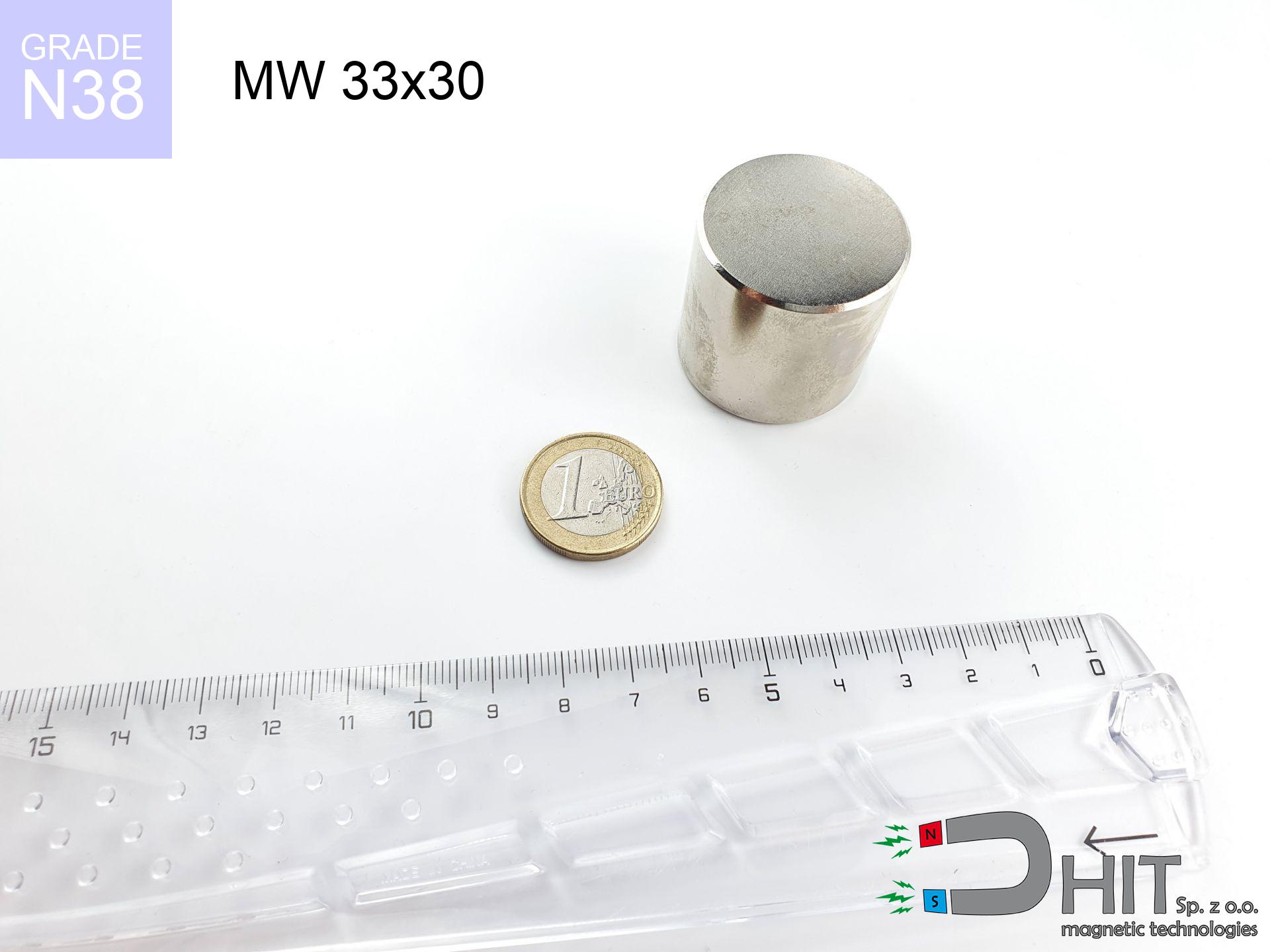
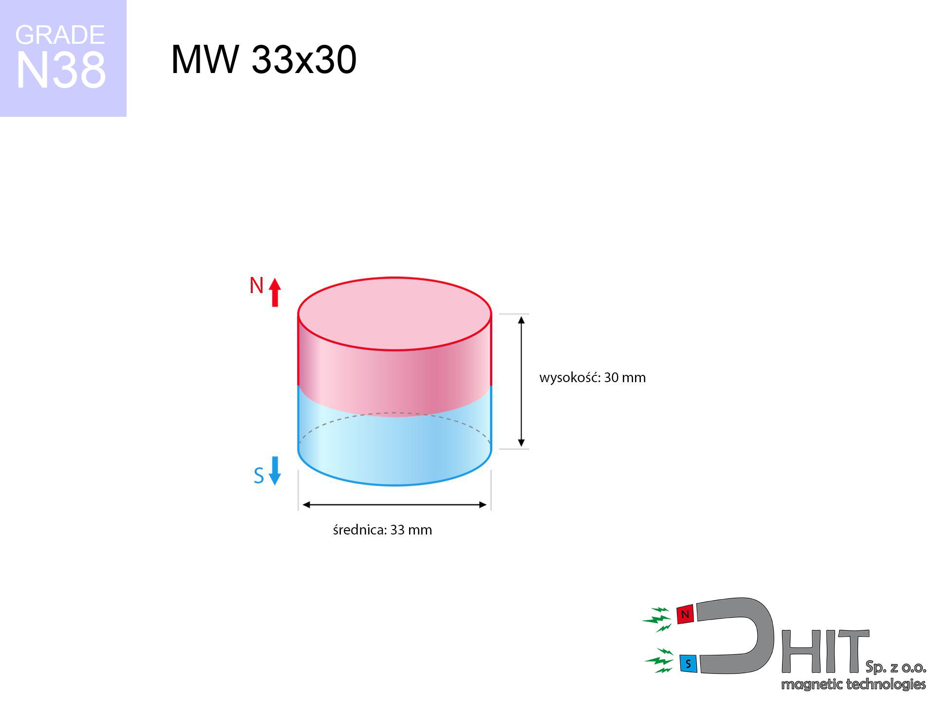
MW 33x30 / N38 - cylindrical magnet
cylindrical magnet
Catalog no 010058
GTIN/EAN: 5906301810575
Diameter Ø
33 mm [±0,1 mm]
Height
30 mm [±0,1 mm]
Weight
192.44 g
Magnetization Direction
↑ axial
Load capacity
35.84 kg / 351.54 N
Magnetic Induction
543.05 mT / 5430 Gs
Coating
[NiCuNi] Nickel
52.89 ZŁ with VAT / pcs + price for transport
43.00 ZŁ net + 23% VAT / pcs
bulk discounts:
Need more?
Call us now
+48 888 99 98 98
if you prefer let us know via
contact form
our website.
Weight and form of a magnet can be verified using our
magnetic calculator.
Same-day shipping for orders placed before 14:00.
Technical - MW 33x30 / N38 - cylindrical magnet
Specification / characteristics - MW 33x30 / N38 - cylindrical magnet
| properties | values |
|---|---|
| Cat. no. | 010058 |
| GTIN/EAN | 5906301810575 |
| Production/Distribution | Dhit sp. z o.o. |
| Country of origin | Poland / China / Germany |
| Customs code | 85059029 |
| Diameter Ø | 33 mm [±0,1 mm] |
| Height | 30 mm [±0,1 mm] |
| Weight | 192.44 g |
| Magnetization Direction | ↑ axial |
| Load capacity ~ ? | 35.84 kg / 351.54 N |
| Magnetic Induction ~ ? | 543.05 mT / 5430 Gs |
| Coating | [NiCuNi] Nickel |
| Manufacturing Tolerance | ±0.1 mm |
Magnetic properties of material N38
| properties | values | units |
|---|---|---|
| remenance Br [min. - max.] ? | 12.2-12.6 | kGs |
| remenance Br [min. - max.] ? | 1220-1260 | mT |
| coercivity bHc ? | 10.8-11.5 | kOe |
| coercivity bHc ? | 860-915 | kA/m |
| actual internal force iHc | ≥ 12 | kOe |
| actual internal force iHc | ≥ 955 | kA/m |
| energy density [min. - max.] ? | 36-38 | BH max MGOe |
| energy density [min. - max.] ? | 287-303 | BH max KJ/m |
| max. temperature ? | ≤ 80 | °C |
Physical properties of sintered neodymium magnets Nd2Fe14B at 20°C
| properties | values | units |
|---|---|---|
| Vickers hardness | ≥550 | Hv |
| Density | ≥7.4 | g/cm3 |
| Curie Temperature TC | 312 - 380 | °C |
| Curie Temperature TF | 593 - 716 | °F |
| Specific resistance | 150 | μΩ⋅cm |
| Bending strength | 250 | MPa |
| Compressive strength | 1000~1100 | MPa |
| Thermal expansion parallel (∥) to orientation (M) | (3-4) x 10-6 | °C-1 |
| Thermal expansion perpendicular (⊥) to orientation (M) | -(1-3) x 10-6 | °C-1 |
| Young's modulus | 1.7 x 10⁴ | kg/mm² |
Technical simulation of the product - data
Presented information are the result of a engineering calculation. Values rely on models for the material Nd2Fe14B. Actual parameters may deviate from the simulation results. Treat these calculations as a preliminary roadmap during assembly planning.
Table 1: Static force (force vs distance) - interaction chart
MW 33x30 / N38
| Distance (mm) | Induction (Gauss) / mT | Pull Force (kg/lbs/g/N) | Risk Status |
|---|---|---|---|
| 0 mm |
5429 Gs
542.9 mT
|
35.84 kg / 79.01 pounds
35840.0 g / 351.6 N
|
crushing |
| 1 mm |
5098 Gs
509.8 mT
|
31.60 kg / 69.67 pounds
31600.1 g / 310.0 N
|
crushing |
| 2 mm |
4765 Gs
476.5 mT
|
27.60 kg / 60.85 pounds
27601.7 g / 270.8 N
|
crushing |
| 3 mm |
4436 Gs
443.6 mT
|
23.93 kg / 52.76 pounds
23930.4 g / 234.8 N
|
crushing |
| 5 mm |
3810 Gs
381.0 mT
|
17.65 kg / 38.91 pounds
17650.2 g / 173.1 N
|
crushing |
| 10 mm |
2518 Gs
251.8 mT
|
7.71 kg / 17.00 pounds
7709.5 g / 75.6 N
|
warning |
| 15 mm |
1650 Gs
165.0 mT
|
3.31 kg / 7.30 pounds
3312.1 g / 32.5 N
|
warning |
| 20 mm |
1105 Gs
110.5 mT
|
1.49 kg / 3.27 pounds
1485.1 g / 14.6 N
|
weak grip |
| 30 mm |
546 Gs
54.6 mT
|
0.36 kg / 0.80 pounds
361.9 g / 3.5 N
|
weak grip |
| 50 mm |
184 Gs
18.4 mT
|
0.04 kg / 0.09 pounds
41.4 g / 0.4 N
|
weak grip |
Table 2: Shear capacity (vertical surface)
MW 33x30 / N38
| Distance (mm) | Friction coefficient | Pull Force (kg/lbs/g/N) |
|---|---|---|
| 0 mm | Stal (~0.2) |
7.17 kg / 15.80 pounds
7168.0 g / 70.3 N
|
| 1 mm | Stal (~0.2) |
6.32 kg / 13.93 pounds
6320.0 g / 62.0 N
|
| 2 mm | Stal (~0.2) |
5.52 kg / 12.17 pounds
5520.0 g / 54.2 N
|
| 3 mm | Stal (~0.2) |
4.79 kg / 10.55 pounds
4786.0 g / 47.0 N
|
| 5 mm | Stal (~0.2) |
3.53 kg / 7.78 pounds
3530.0 g / 34.6 N
|
| 10 mm | Stal (~0.2) |
1.54 kg / 3.40 pounds
1542.0 g / 15.1 N
|
| 15 mm | Stal (~0.2) |
0.66 kg / 1.46 pounds
662.0 g / 6.5 N
|
| 20 mm | Stal (~0.2) |
0.30 kg / 0.66 pounds
298.0 g / 2.9 N
|
| 30 mm | Stal (~0.2) |
0.07 kg / 0.16 pounds
72.0 g / 0.7 N
|
| 50 mm | Stal (~0.2) |
0.01 kg / 0.02 pounds
8.0 g / 0.1 N
|
Table 3: Wall mounting (sliding) - behavior on slippery surfaces
MW 33x30 / N38
| Surface type | Friction coefficient / % Mocy | Max load (kg/lbs/g/N) |
|---|---|---|
| Raw steel |
µ = 0.3
30% Nominalnej Siły
|
10.75 kg / 23.70 pounds
10752.0 g / 105.5 N
|
| Painted steel (standard) |
µ = 0.2
20% Nominalnej Siły
|
7.17 kg / 15.80 pounds
7168.0 g / 70.3 N
|
| Oily/slippery steel |
µ = 0.1
10% Nominalnej Siły
|
3.58 kg / 7.90 pounds
3584.0 g / 35.2 N
|
| Magnet with anti-slip rubber |
µ = 0.5
50% Nominalnej Siły
|
17.92 kg / 39.51 pounds
17920.0 g / 175.8 N
|
Table 4: Steel thickness (substrate influence) - sheet metal selection
MW 33x30 / N38
| Steel thickness (mm) | % power | Real pull force (kg/lbs/g/N) |
|---|---|---|
| 0.5 mm |
|
1.79 kg / 3.95 pounds
1792.0 g / 17.6 N
|
| 1 mm |
|
4.48 kg / 9.88 pounds
4480.0 g / 43.9 N
|
| 2 mm |
|
8.96 kg / 19.75 pounds
8960.0 g / 87.9 N
|
| 3 mm |
|
13.44 kg / 29.63 pounds
13440.0 g / 131.8 N
|
| 5 mm |
|
22.40 kg / 49.38 pounds
22400.0 g / 219.7 N
|
| 10 mm |
|
35.84 kg / 79.01 pounds
35840.0 g / 351.6 N
|
| 11 mm |
|
35.84 kg / 79.01 pounds
35840.0 g / 351.6 N
|
| 12 mm |
|
35.84 kg / 79.01 pounds
35840.0 g / 351.6 N
|
Table 5: Thermal stability (stability) - thermal limit
MW 33x30 / N38
| Ambient temp. (°C) | Power loss | Remaining pull (kg/lbs/g/N) | Status |
|---|---|---|---|
| 20 °C | 0.0% |
35.84 kg / 79.01 pounds
35840.0 g / 351.6 N
|
OK |
| 40 °C | -2.2% |
35.05 kg / 77.28 pounds
35051.5 g / 343.9 N
|
OK |
| 60 °C | -4.4% |
34.26 kg / 75.54 pounds
34263.0 g / 336.1 N
|
OK |
| 80 °C | -6.6% |
33.47 kg / 73.80 pounds
33474.6 g / 328.4 N
|
|
| 100 °C | -28.8% |
25.52 kg / 56.26 pounds
25518.1 g / 250.3 N
|
Table 6: Magnet-Magnet interaction (repulsion) - field collision
MW 33x30 / N38
| Gap (mm) | Attraction (kg/lbs) (N-S) | Shear Strength (kg/lbs/g/N) | Repulsion (kg/lbs) (N-N) |
|---|---|---|---|
| 0 mm |
155.43 kg / 342.66 pounds
5 974 Gs
|
23.31 kg / 51.40 pounds
23314 g / 228.7 N
|
N/A |
| 1 mm |
146.19 kg / 322.29 pounds
10 531 Gs
|
21.93 kg / 48.34 pounds
21928 g / 215.1 N
|
131.57 kg / 290.06 pounds
~0 Gs
|
| 2 mm |
137.04 kg / 302.12 pounds
10 196 Gs
|
20.56 kg / 45.32 pounds
20556 g / 201.7 N
|
123.34 kg / 271.91 pounds
~0 Gs
|
| 3 mm |
128.20 kg / 282.64 pounds
9 862 Gs
|
19.23 kg / 42.40 pounds
19230 g / 188.6 N
|
115.38 kg / 254.37 pounds
~0 Gs
|
| 5 mm |
111.55 kg / 245.93 pounds
9 199 Gs
|
16.73 kg / 36.89 pounds
16733 g / 164.2 N
|
100.40 kg / 221.34 pounds
~0 Gs
|
| 10 mm |
76.54 kg / 168.75 pounds
7 620 Gs
|
11.48 kg / 25.31 pounds
11481 g / 112.6 N
|
68.89 kg / 151.87 pounds
~0 Gs
|
| 20 mm |
33.43 kg / 73.71 pounds
5 036 Gs
|
5.02 kg / 11.06 pounds
5015 g / 49.2 N
|
30.09 kg / 66.34 pounds
~0 Gs
|
| 50 mm |
3.08 kg / 6.78 pounds
1 528 Gs
|
0.46 kg / 1.02 pounds
462 g / 4.5 N
|
2.77 kg / 6.11 pounds
~0 Gs
|
| 60 mm |
1.57 kg / 3.46 pounds
1 091 Gs
|
0.24 kg / 0.52 pounds
235 g / 2.3 N
|
1.41 kg / 3.11 pounds
~0 Gs
|
| 70 mm |
0.85 kg / 1.87 pounds
803 Gs
|
0.13 kg / 0.28 pounds
127 g / 1.2 N
|
0.76 kg / 1.69 pounds
~0 Gs
|
| 80 mm |
0.48 kg / 1.07 pounds
606 Gs
|
0.07 kg / 0.16 pounds
73 g / 0.7 N
|
0.44 kg / 0.96 pounds
~0 Gs
|
| 90 mm |
0.29 kg / 0.64 pounds
468 Gs
|
0.04 kg / 0.10 pounds
43 g / 0.4 N
|
0.26 kg / 0.57 pounds
~0 Gs
|
| 100 mm |
0.18 kg / 0.40 pounds
369 Gs
|
0.03 kg / 0.06 pounds
27 g / 0.3 N
|
0.16 kg / 0.36 pounds
~0 Gs
|
Table 7: Hazards (electronics) - precautionary measures
MW 33x30 / N38
| Object / Device | Limit (Gauss) / mT | Safe distance |
|---|---|---|
| Pacemaker | 5 Gs (0.5 mT) | 20.5 cm |
| Hearing aid | 10 Gs (1.0 mT) | 16.0 cm |
| Mechanical watch | 20 Gs (2.0 mT) | 12.5 cm |
| Phone / Smartphone | 40 Gs (4.0 mT) | 9.5 cm |
| Remote | 50 Gs (5.0 mT) | 9.0 cm |
| Payment card | 400 Gs (40.0 mT) | 4.0 cm |
| HDD hard drive | 600 Gs (60.0 mT) | 3.0 cm |
Table 8: Dynamics (cracking risk) - warning
MW 33x30 / N38
| Start from (mm) | Speed (km/h) | Energy (J) | Predicted outcome |
|---|---|---|---|
| 10 mm |
15.50 km/h
(4.31 m/s)
|
1.78 J | |
| 30 mm |
23.99 km/h
(6.66 m/s)
|
4.27 J | |
| 50 mm |
30.80 km/h
(8.55 m/s)
|
7.04 J | |
| 100 mm |
43.52 km/h
(12.09 m/s)
|
14.06 J |
Table 9: Anti-corrosion coating durability
MW 33x30 / N38
| Technical parameter | Value / Description |
|---|---|
| Coating type | [NiCuNi] Nickel |
| Layer structure | Nickel - Copper - Nickel |
| Layer thickness | 10-20 µm |
| Salt spray test (SST) ? | 24 h |
| Recommended environment | Indoors only (dry) |
Table 10: Electrical data (Flux)
MW 33x30 / N38
| Parameter | Value | SI Unit / Description |
|---|---|---|
| Magnetic Flux | 47 447 Mx | 474.5 µWb |
| Pc Coefficient | 0.85 | High (Stable) |
Table 11: Submerged application
MW 33x30 / N38
| Environment | Effective steel pull | Effect |
|---|---|---|
| Air (land) | 35.84 kg | Standard |
| Water (riverbed) |
41.04 kg
(+5.20 kg buoyancy gain)
|
+14.5% |
1. Sliding resistance
*Warning: On a vertical wall, the magnet holds merely a fraction of its perpendicular strength.
2. Steel thickness impact
*Thin metal sheet (e.g. computer case) significantly weakens the holding force.
3. Heat tolerance
*For N38 grade, the critical limit is 80°C.
4. Demagnetization curve and operating point (B-H)
chart generated for the permeance coefficient Pc (Permeance Coefficient) = 0.85
The chart above illustrates the magnetic characteristics of the material within the second quadrant of the hysteresis loop. The solid red line represents the demagnetization curve (material potential), while the dashed blue line is the load line based on the magnet's geometry. The Pc (Permeance Coefficient), also known as the load line slope, is a dimensionless value that describes the relationship between the magnet's shape and its magnetic stability. The intersection of these two lines (the black dot) is the operating point — it determines the actual magnetic flux density generated by the magnet in this specific configuration. A higher Pc value means the magnet is more 'slender' (tall relative to its area), resulting in a higher operating point and better resistance to irreversible demagnetization caused by external fields or temperature. A value of 0.42 is relatively low (typical for flat magnets), meaning the operating point is closer to the 'knee' of the curve — caution is advised when operating at temperatures near the maximum limit to avoid strength loss.
Elemental analysis
| iron (Fe) | 64% – 68% |
| neodymium (Nd) | 29% – 32% |
| boron (B) | 1.1% – 1.2% |
| dysprosium (Dy) | 0.5% – 2.0% |
| coating (Ni-Cu-Ni) | < 0.05% |
Ecology and recycling (GPSR)
| recyclability (EoL) | 100% |
| recycled raw materials | ~10% (pre-cons) |
| carbon footprint | low / zredukowany |
| waste code (EWC) | 16 02 16 |
Other deals


![UMGW 75x33x18 [M10] GW / N38 - magnetic holder internal thread](https://cdn3.dhit.pl/graphics/products/umgw-75x33x18-m10-gw-cak.jpg "UMGW 75x33x18 [M10] GW / N38 - magnetic holder internal thread")

Pros as well as cons of rare earth magnets.
Advantages
- They virtually do not lose strength, because even after 10 years the decline in efficiency is only ~1% (based on calculations),
- They do not lose their magnetic properties even under external field action,
- A magnet with a smooth silver surface has better aesthetics,
- They are known for high magnetic induction at the operating surface, which improves attraction properties,
- Through (adequate) combination of ingredients, they can achieve high thermal strength, allowing for functioning at temperatures reaching 230°C and above...
- Possibility of custom shaping as well as adapting to defined needs,
- Versatile presence in modern industrial fields – they are utilized in hard drives, drive modules, medical equipment, also complex engineering applications.
- Compactness – despite small sizes they offer powerful magnetic field, making them ideal for precision applications
Limitations
- Brittleness is one of their disadvantages. Upon strong impact they can break. We recommend keeping them in a steel housing, which not only secures them against impacts but also raises their durability
- Neodymium magnets lose power when exposed to high temperatures. After reaching 80°C, many of them experience permanent drop of strength (a factor is the shape and dimensions of the magnet). We offer magnets specially adapted to work at temperatures up to 230°C marked [AH], which are very resistant to heat
- Magnets exposed to a humid environment can rust. Therefore while using outdoors, we advise using water-impermeable magnets made of rubber, plastic or other material resistant to moisture
- We recommend a housing - magnetic mechanism, due to difficulties in producing threads inside the magnet and complicated shapes.
- Potential hazard to health – tiny shards of magnets pose a threat, in case of ingestion, which becomes key in the context of child safety. Furthermore, small elements of these magnets are able to complicate diagnosis medical after entering the body.
- Due to neodymium price, their price exceeds standard values,
Pull force analysis
Highest magnetic holding force – what contributes to it?
- using a sheet made of high-permeability steel, acting as a circuit closing element
- possessing a thickness of at least 10 mm to avoid saturation
- with a surface free of scratches
- with zero gap (no coatings)
- under vertical force vector (90-degree angle)
- at ambient temperature approx. 20 degrees Celsius
Practical lifting capacity: influencing factors
- Air gap (betwixt the magnet and the plate), because even a very small distance (e.g. 0.5 mm) leads to a drastic drop in force by up to 50% (this also applies to paint, corrosion or dirt).
- Pull-off angle – note that the magnet has greatest strength perpendicularly. Under shear forces, the capacity drops significantly, often to levels of 20-30% of the maximum value.
- Base massiveness – insufficiently thick sheet does not close the flux, causing part of the flux to be escaped to the other side.
- Plate material – mild steel gives the best results. Alloy admixtures decrease magnetic properties and lifting capacity.
- Surface finish – ideal contact is obtained only on polished steel. Rough texture create air cushions, weakening the magnet.
- Thermal factor – hot environment weakens pulling force. Too high temperature can permanently demagnetize the magnet.
Lifting capacity testing was performed on plates with a smooth surface of suitable thickness, under perpendicular forces, in contrast under attempts to slide the magnet the holding force is lower. Moreover, even a slight gap between the magnet’s surface and the plate lowers the load capacity.
H&S for magnets
Demagnetization risk
Regular neodymium magnets (N-type) undergo demagnetization when the temperature exceeds 80°C. This process is irreversible.
Machining danger
Fire warning: Neodymium dust is explosive. Avoid machining magnets in home conditions as this may cause fire.
Serious injuries
Large magnets can break fingers instantly. Do not place your hand between two attracting surfaces.
Keep away from computers
Device Safety: Strong magnets can damage payment cards and sensitive devices (pacemakers, medical aids, timepieces).
Danger to the youngest
Adult use only. Tiny parts pose a choking risk, causing severe trauma. Store away from kids and pets.
Phone sensors
An intense magnetic field negatively affects the operation of magnetometers in smartphones and navigation systems. Maintain magnets close to a smartphone to prevent breaking the sensors.
Immense force
Use magnets with awareness. Their huge power can surprise even professionals. Be vigilant and respect their force.
Allergic reactions
Studies show that nickel (the usual finish) is a strong allergen. If you have an allergy, refrain from direct skin contact and opt for coated magnets.
Eye protection
Beware of splinters. Magnets can fracture upon uncontrolled impact, launching sharp fragments into the air. We recommend safety glasses.
ICD Warning
Health Alert: Strong magnets can deactivate pacemakers and defibrillators. Do not approach if you have electronic implants.
Tabela kosztu i czasu dostawy
Płatność przed wysyłką:

GLS kurier
Przesyłka będzie u Ciebie za 2-3 dni
14.99 ZŁ

InPost Paczkomaty 24/7
Przesyłka będzie u Ciebie za 1-2 dni
12.30 ZŁ
Płatność przy odbiorze (pobranie):
GLS kurier
Przesyłka będzie u Ciebie za 1-2 dni
23.00 ZŁ
Rate the product
Your rating