
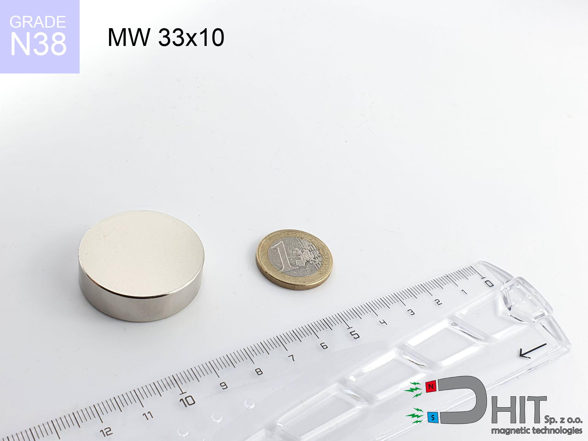
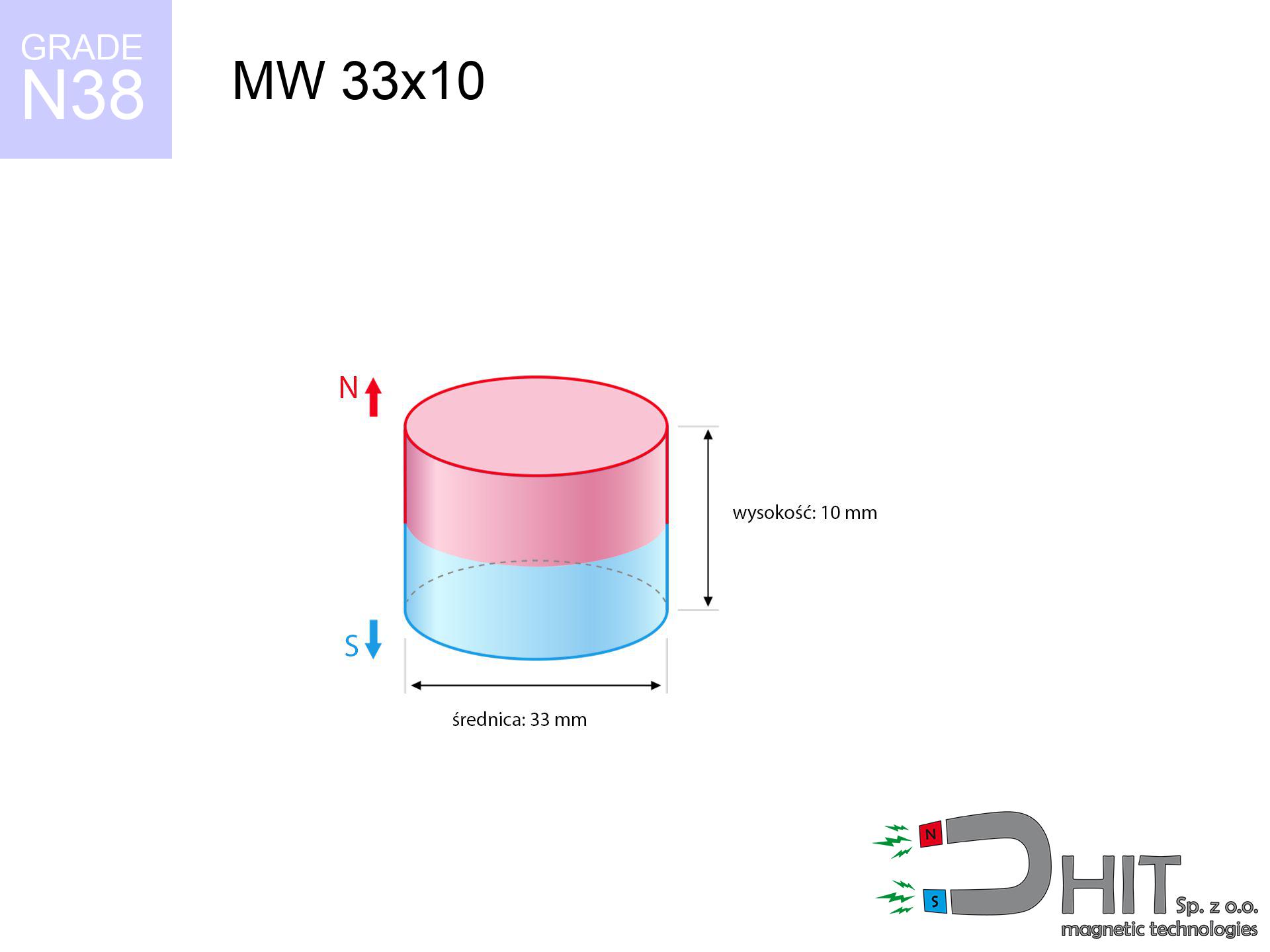
MW 33x10 / N38 - cylindrical magnet
cylindrical magnet
Catalog no 010057
GTIN/EAN: 5906301810568
Diameter Ø
33 mm [±0,1 mm]
Height
10 mm [±0,1 mm]
Weight
64.15 g
Magnetization Direction
↑ axial
Load capacity
23.67 kg / 232.15 N
Magnetic Induction
321.26 mT / 3213 Gs
Coating
[NiCuNi] Nickel
26.52 ZŁ with VAT / pcs + price for transport
21.56 ZŁ net + 23% VAT / pcs
bulk discounts:
Need more?
Pick up the phone and ask
+48 888 99 98 98
or send us a note by means of
form
the contact page.
Weight as well as form of a magnet can be estimated on our
modular calculator.
Same-day shipping for orders placed before 14:00.
Technical data - MW 33x10 / N38 - cylindrical magnet
Specification / characteristics - MW 33x10 / N38 - cylindrical magnet
| properties | values |
|---|---|
| Cat. no. | 010057 |
| GTIN/EAN | 5906301810568 |
| Production/Distribution | Dhit sp. z o.o. |
| Country of origin | Poland / China / Germany |
| Customs code | 85059029 |
| Diameter Ø | 33 mm [±0,1 mm] |
| Height | 10 mm [±0,1 mm] |
| Weight | 64.15 g |
| Magnetization Direction | ↑ axial |
| Load capacity ~ ? | 23.67 kg / 232.15 N |
| Magnetic Induction ~ ? | 321.26 mT / 3213 Gs |
| Coating | [NiCuNi] Nickel |
| Manufacturing Tolerance | ±0.1 mm |
Magnetic properties of material N38
| properties | values | units |
|---|---|---|
| remenance Br [min. - max.] ? | 12.2-12.6 | kGs |
| remenance Br [min. - max.] ? | 1220-1260 | mT |
| coercivity bHc ? | 10.8-11.5 | kOe |
| coercivity bHc ? | 860-915 | kA/m |
| actual internal force iHc | ≥ 12 | kOe |
| actual internal force iHc | ≥ 955 | kA/m |
| energy density [min. - max.] ? | 36-38 | BH max MGOe |
| energy density [min. - max.] ? | 287-303 | BH max KJ/m |
| max. temperature ? | ≤ 80 | °C |
Physical properties of sintered neodymium magnets Nd2Fe14B at 20°C
| properties | values | units |
|---|---|---|
| Vickers hardness | ≥550 | Hv |
| Density | ≥7.4 | g/cm3 |
| Curie Temperature TC | 312 - 380 | °C |
| Curie Temperature TF | 593 - 716 | °F |
| Specific resistance | 150 | μΩ⋅cm |
| Bending strength | 250 | MPa |
| Compressive strength | 1000~1100 | MPa |
| Thermal expansion parallel (∥) to orientation (M) | (3-4) x 10-6 | °C-1 |
| Thermal expansion perpendicular (⊥) to orientation (M) | -(1-3) x 10-6 | °C-1 |
| Young's modulus | 1.7 x 10⁴ | kg/mm² |
Engineering modeling of the magnet - technical parameters
Presented values constitute the direct effect of a physical simulation. Values rely on models for the class Nd2Fe14B. Real-world conditions may differ from theoretical values. Treat these calculations as a preliminary roadmap when designing systems.
Table 1: Static force (pull vs gap) - interaction chart
MW 33x10 / N38
| Distance (mm) | Induction (Gauss) / mT | Pull Force (kg/lbs/g/N) | Risk Status |
|---|---|---|---|
| 0 mm |
3212 Gs
321.2 mT
|
23.67 kg / 52.18 LBS
23670.0 g / 232.2 N
|
critical level |
| 1 mm |
3064 Gs
306.4 mT
|
21.54 kg / 47.49 LBS
21539.1 g / 211.3 N
|
critical level |
| 2 mm |
2901 Gs
290.1 mT
|
19.30 kg / 42.55 LBS
19302.3 g / 189.4 N
|
critical level |
| 3 mm |
2728 Gs
272.8 mT
|
17.07 kg / 37.64 LBS
17072.3 g / 167.5 N
|
critical level |
| 5 mm |
2373 Gs
237.3 mT
|
12.91 kg / 28.47 LBS
12913.7 g / 126.7 N
|
critical level |
| 10 mm |
1569 Gs
156.9 mT
|
5.65 kg / 12.45 LBS
5648.1 g / 55.4 N
|
medium risk |
| 15 mm |
1004 Gs
100.4 mT
|
2.31 kg / 5.10 LBS
2312.6 g / 22.7 N
|
medium risk |
| 20 mm |
650 Gs
65.0 mT
|
0.97 kg / 2.14 LBS
969.4 g / 9.5 N
|
weak grip |
| 30 mm |
299 Gs
29.9 mT
|
0.21 kg / 0.45 LBS
205.1 g / 2.0 N
|
weak grip |
| 50 mm |
90 Gs
9.0 mT
|
0.02 kg / 0.04 LBS
18.7 g / 0.2 N
|
weak grip |
Table 2: Shear capacity (wall)
MW 33x10 / N38
| Distance (mm) | Friction coefficient | Pull Force (kg/lbs/g/N) |
|---|---|---|
| 0 mm | Stal (~0.2) |
4.73 kg / 10.44 LBS
4734.0 g / 46.4 N
|
| 1 mm | Stal (~0.2) |
4.31 kg / 9.50 LBS
4308.0 g / 42.3 N
|
| 2 mm | Stal (~0.2) |
3.86 kg / 8.51 LBS
3860.0 g / 37.9 N
|
| 3 mm | Stal (~0.2) |
3.41 kg / 7.53 LBS
3414.0 g / 33.5 N
|
| 5 mm | Stal (~0.2) |
2.58 kg / 5.69 LBS
2582.0 g / 25.3 N
|
| 10 mm | Stal (~0.2) |
1.13 kg / 2.49 LBS
1130.0 g / 11.1 N
|
| 15 mm | Stal (~0.2) |
0.46 kg / 1.02 LBS
462.0 g / 4.5 N
|
| 20 mm | Stal (~0.2) |
0.19 kg / 0.43 LBS
194.0 g / 1.9 N
|
| 30 mm | Stal (~0.2) |
0.04 kg / 0.09 LBS
42.0 g / 0.4 N
|
| 50 mm | Stal (~0.2) |
0.00 kg / 0.01 LBS
4.0 g / 0.0 N
|
Table 3: Wall mounting (sliding) - vertical pull
MW 33x10 / N38
| Surface type | Friction coefficient / % Mocy | Max load (kg/lbs/g/N) |
|---|---|---|
| Raw steel |
µ = 0.3
30% Nominalnej Siły
|
7.10 kg / 15.66 LBS
7101.0 g / 69.7 N
|
| Painted steel (standard) |
µ = 0.2
20% Nominalnej Siły
|
4.73 kg / 10.44 LBS
4734.0 g / 46.4 N
|
| Oily/slippery steel |
µ = 0.1
10% Nominalnej Siły
|
2.37 kg / 5.22 LBS
2367.0 g / 23.2 N
|
| Magnet with anti-slip rubber |
µ = 0.5
50% Nominalnej Siły
|
11.84 kg / 26.09 LBS
11835.0 g / 116.1 N
|
Table 4: Material efficiency (substrate influence) - power losses
MW 33x10 / N38
| Steel thickness (mm) | % power | Real pull force (kg/lbs/g/N) |
|---|---|---|
| 0.5 mm |
|
1.18 kg / 2.61 LBS
1183.5 g / 11.6 N
|
| 1 mm |
|
2.96 kg / 6.52 LBS
2958.8 g / 29.0 N
|
| 2 mm |
|
5.92 kg / 13.05 LBS
5917.5 g / 58.1 N
|
| 3 mm |
|
8.88 kg / 19.57 LBS
8876.3 g / 87.1 N
|
| 5 mm |
|
14.79 kg / 32.61 LBS
14793.8 g / 145.1 N
|
| 10 mm |
|
23.67 kg / 52.18 LBS
23670.0 g / 232.2 N
|
| 11 mm |
|
23.67 kg / 52.18 LBS
23670.0 g / 232.2 N
|
| 12 mm |
|
23.67 kg / 52.18 LBS
23670.0 g / 232.2 N
|
Table 5: Thermal stability (stability) - resistance threshold
MW 33x10 / N38
| Ambient temp. (°C) | Power loss | Remaining pull (kg/lbs/g/N) | Status |
|---|---|---|---|
| 20 °C | 0.0% |
23.67 kg / 52.18 LBS
23670.0 g / 232.2 N
|
OK |
| 40 °C | -2.2% |
23.15 kg / 51.04 LBS
23149.3 g / 227.1 N
|
OK |
| 60 °C | -4.4% |
22.63 kg / 49.89 LBS
22628.5 g / 222.0 N
|
|
| 80 °C | -6.6% |
22.11 kg / 48.74 LBS
22107.8 g / 216.9 N
|
|
| 100 °C | -28.8% |
16.85 kg / 37.15 LBS
16853.0 g / 165.3 N
|
Table 6: Two magnets (attraction) - field range
MW 33x10 / N38
| Gap (mm) | Attraction (kg/lbs) (N-S) | Lateral Force (kg/lbs/g/N) | Repulsion (kg/lbs) (N-N) |
|---|---|---|---|
| 0 mm |
54.40 kg / 119.94 LBS
4 780 Gs
|
8.16 kg / 17.99 LBS
8160 g / 80.1 N
|
N/A |
| 1 mm |
52.02 kg / 114.68 LBS
6 282 Gs
|
7.80 kg / 17.20 LBS
7803 g / 76.5 N
|
46.82 kg / 103.21 LBS
~0 Gs
|
| 2 mm |
49.51 kg / 109.14 LBS
6 128 Gs
|
7.43 kg / 16.37 LBS
7426 g / 72.8 N
|
44.55 kg / 98.23 LBS
~0 Gs
|
| 3 mm |
46.95 kg / 103.50 LBS
5 968 Gs
|
7.04 kg / 15.52 LBS
7042 g / 69.1 N
|
42.25 kg / 93.15 LBS
~0 Gs
|
| 5 mm |
41.79 kg / 92.13 LBS
5 630 Gs
|
6.27 kg / 13.82 LBS
6268 g / 61.5 N
|
37.61 kg / 82.91 LBS
~0 Gs
|
| 10 mm |
29.68 kg / 65.43 LBS
4 745 Gs
|
4.45 kg / 9.82 LBS
4452 g / 43.7 N
|
26.71 kg / 58.89 LBS
~0 Gs
|
| 20 mm |
12.98 kg / 28.62 LBS
3 138 Gs
|
1.95 kg / 4.29 LBS
1947 g / 19.1 N
|
11.68 kg / 25.76 LBS
~0 Gs
|
| 50 mm |
0.99 kg / 2.18 LBS
867 Gs
|
0.15 kg / 0.33 LBS
149 g / 1.5 N
|
0.89 kg / 1.97 LBS
~0 Gs
|
| 60 mm |
0.47 kg / 1.04 LBS
598 Gs
|
0.07 kg / 0.16 LBS
71 g / 0.7 N
|
0.42 kg / 0.94 LBS
~0 Gs
|
| 70 mm |
0.24 kg / 0.53 LBS
426 Gs
|
0.04 kg / 0.08 LBS
36 g / 0.4 N
|
0.22 kg / 0.47 LBS
~0 Gs
|
| 80 mm |
0.13 kg / 0.28 LBS
312 Gs
|
0.02 kg / 0.04 LBS
19 g / 0.2 N
|
0.12 kg / 0.26 LBS
~0 Gs
|
| 90 mm |
0.07 kg / 0.16 LBS
235 Gs
|
0.01 kg / 0.02 LBS
11 g / 0.1 N
|
0.07 kg / 0.14 LBS
~0 Gs
|
| 100 mm |
0.04 kg / 0.09 LBS
181 Gs
|
0.01 kg / 0.01 LBS
6 g / 0.1 N
|
0.04 kg / 0.09 LBS
~0 Gs
|
Table 7: Protective zones (electronics) - warnings
MW 33x10 / N38
| Object / Device | Limit (Gauss) / mT | Safe distance |
|---|---|---|
| Pacemaker | 5 Gs (0.5 mT) | 14.5 cm |
| Hearing aid | 10 Gs (1.0 mT) | 11.5 cm |
| Mechanical watch | 20 Gs (2.0 mT) | 9.0 cm |
| Mobile device | 40 Gs (4.0 mT) | 7.0 cm |
| Car key | 50 Gs (5.0 mT) | 6.5 cm |
| Payment card | 400 Gs (40.0 mT) | 3.0 cm |
| HDD hard drive | 600 Gs (60.0 mT) | 2.5 cm |
Table 8: Impact energy (cracking risk) - warning
MW 33x10 / N38
| Start from (mm) | Speed (km/h) | Energy (J) | Predicted outcome |
|---|---|---|---|
| 10 mm |
22.07 km/h
(6.13 m/s)
|
1.21 J | |
| 30 mm |
33.74 km/h
(9.37 m/s)
|
2.82 J | |
| 50 mm |
43.34 km/h
(12.04 m/s)
|
4.65 J | |
| 100 mm |
61.26 km/h
(17.02 m/s)
|
9.29 J |
Table 9: Coating parameters (durability)
MW 33x10 / N38
| Technical parameter | Value / Description |
|---|---|
| Coating type | [NiCuNi] Nickel |
| Layer structure | Nickel - Copper - Nickel |
| Layer thickness | 10-20 µm |
| Salt spray test (SST) ? | 24 h |
| Recommended environment | Indoors only (dry) |
Table 10: Electrical data (Pc)
MW 33x10 / N38
| Parameter | Value | SI Unit / Description |
|---|---|---|
| Magnetic Flux | 29 509 Mx | 295.1 µWb |
| Pc Coefficient | 0.40 | Low (Flat) |
Table 11: Underwater work (magnet fishing)
MW 33x10 / N38
| Environment | Effective steel pull | Effect |
|---|---|---|
| Air (land) | 23.67 kg | Standard |
| Water (riverbed) |
27.10 kg
(+3.43 kg buoyancy gain)
|
+14.5% |
1. Shear force
*Note: On a vertical surface, the magnet retains merely approx. 20-30% of its nominal pull.
2. Plate thickness effect
*Thin metal sheet (e.g. 0.5mm PC case) drastically weakens the holding force.
3. Power loss vs temp
*For N38 material, the max working temp is 80°C.
4. Demagnetization curve and operating point (B-H)
chart generated for the permeance coefficient Pc (Permeance Coefficient) = 0.40
This simulation demonstrates the magnetic stability of the selected magnet under specific geometric conditions. The solid red line represents the demagnetization curve (material potential), while the dashed blue line is the load line based on the magnet's geometry. The Pc (Permeance Coefficient), also known as the load line slope, is a dimensionless value that describes the relationship between the magnet's shape and its magnetic stability. The intersection of these two lines (the black dot) is the operating point — it determines the actual magnetic flux density generated by the magnet in this specific configuration. A higher Pc value means the magnet is more 'slender' (tall relative to its area), resulting in a higher operating point and better resistance to irreversible demagnetization caused by external fields or temperature. A value of 0.42 is relatively low (typical for flat magnets), meaning the operating point is closer to the 'knee' of the curve — caution is advised when operating at temperatures near the maximum limit to avoid strength loss.
Chemical composition
| iron (Fe) | 64% – 68% |
| neodymium (Nd) | 29% – 32% |
| boron (B) | 1.1% – 1.2% |
| dysprosium (Dy) | 0.5% – 2.0% |
| coating (Ni-Cu-Ni) | < 0.05% |
Sustainability
| recyclability (EoL) | 100% |
| recycled raw materials | ~10% (pre-cons) |
| carbon footprint | low / zredukowany |
| waste code (EWC) | 16 02 16 |
Check out also products


Strengths and weaknesses of Nd2Fe14B magnets.
Benefits
- They have unchanged lifting capacity, and over more than 10 years their performance decreases symbolically – ~1% (according to theory),
- They are extremely resistant to demagnetization induced by presence of other magnetic fields,
- A magnet with a smooth nickel surface looks better,
- They are known for high magnetic induction at the operating surface, making them more effective,
- Through (appropriate) combination of ingredients, they can achieve high thermal strength, enabling action at temperatures approaching 230°C and above...
- Possibility of precise modeling and optimizing to defined requirements,
- Huge importance in future technologies – they are commonly used in HDD drives, brushless drives, medical devices, as well as other advanced devices.
- Compactness – despite small sizes they provide effective action, making them ideal for precision applications
Cons
- They are fragile upon too strong impacts. To avoid cracks, it is worth securing magnets using a steel holder. Such protection not only shields the magnet but also increases its resistance to damage
- Neodymium magnets lose their power under the influence of heating. As soon as 80°C is exceeded, many of them start losing their force. Therefore, we recommend our special magnets marked [AH], which maintain stability even at temperatures up to 230°C
- They oxidize in a humid environment - during use outdoors we suggest using waterproof magnets e.g. in rubber, plastic
- Limited ability of producing threads in the magnet and complicated forms - recommended is a housing - mounting mechanism.
- Potential hazard related to microscopic parts of magnets are risky, if swallowed, which becomes key in the context of child health protection. Additionally, tiny parts of these magnets can be problematic in diagnostics medical when they are in the body.
- High unit price – neodymium magnets are more expensive than other types of magnets (e.g. ferrite), which hinders application in large quantities
Lifting parameters
Highest magnetic holding force – what affects it?
- with the use of a sheet made of low-carbon steel, ensuring maximum field concentration
- whose thickness is min. 10 mm
- with an ground contact surface
- under conditions of gap-free contact (surface-to-surface)
- during pulling in a direction vertical to the mounting surface
- at ambient temperature approx. 20 degrees Celsius
Impact of factors on magnetic holding capacity in practice
- Air gap (betwixt the magnet and the plate), since even a tiny clearance (e.g. 0.5 mm) can cause a drastic drop in force by up to 50% (this also applies to paint, corrosion or debris).
- Pull-off angle – remember that the magnet has greatest strength perpendicularly. Under shear forces, the capacity drops drastically, often to levels of 20-30% of the maximum value.
- Metal thickness – the thinner the sheet, the weaker the hold. Part of the magnetic field passes through the material instead of converting into lifting capacity.
- Metal type – not every steel reacts the same. High carbon content weaken the interaction with the magnet.
- Surface structure – the smoother and more polished the plate, the larger the contact zone and higher the lifting capacity. Roughness acts like micro-gaps.
- Thermal conditions – neodymium magnets have a sensitivity to temperature. At higher temperatures they lose power, and at low temperatures they can be stronger (up to a certain limit).
Lifting capacity was measured with the use of a smooth steel plate of suitable thickness (min. 20 mm), under vertically applied force, whereas under parallel forces the lifting capacity is smaller. Additionally, even a slight gap between the magnet and the plate lowers the lifting capacity.
Precautions when working with NdFeB magnets
Pinching danger
Watch your fingers. Two large magnets will join instantly with a force of massive weight, destroying anything in their path. Exercise extreme caution!
Protective goggles
Neodymium magnets are ceramic materials, meaning they are very brittle. Collision of two magnets will cause them breaking into shards.
Safe operation
Exercise caution. Rare earth magnets act from a long distance and connect with huge force, often faster than you can react.
Data carriers
Avoid bringing magnets near a purse, computer, or TV. The magnetic field can destroy these devices and erase data from cards.
Keep away from children
Absolutely keep magnets out of reach of children. Risk of swallowing is significant, and the consequences of magnets clamping inside the body are very dangerous.
Magnetic interference
Remember: rare earth magnets produce a field that disrupts sensitive sensors. Keep a separation from your phone, tablet, and navigation systems.
Implant safety
Warning for patients: Powerful magnets affect electronics. Maintain minimum 30 cm distance or request help to handle the magnets.
Metal Allergy
It is widely known that nickel (the usual finish) is a potent allergen. For allergy sufferers, refrain from direct skin contact and choose coated magnets.
Combustion hazard
Drilling and cutting of neodymium magnets carries a risk of fire hazard. Neodymium dust reacts violently with oxygen and is hard to extinguish.
Thermal limits
Watch the temperature. Exposing the magnet to high heat will ruin its properties and strength.
Tabela kosztu i czasu dostawy
Płatność przed wysyłką:

GLS kurier
Przesyłka będzie u Ciebie za 2-3 dni
14.99 ZŁ

InPost Paczkomaty 24/7
Przesyłka będzie u Ciebie za 1-2 dni
12.30 ZŁ
Płatność przy odbiorze (pobranie):
GLS kurier
Przesyłka będzie u Ciebie za 1-2 dni
23.00 ZŁ
Rate the product
Your rating