
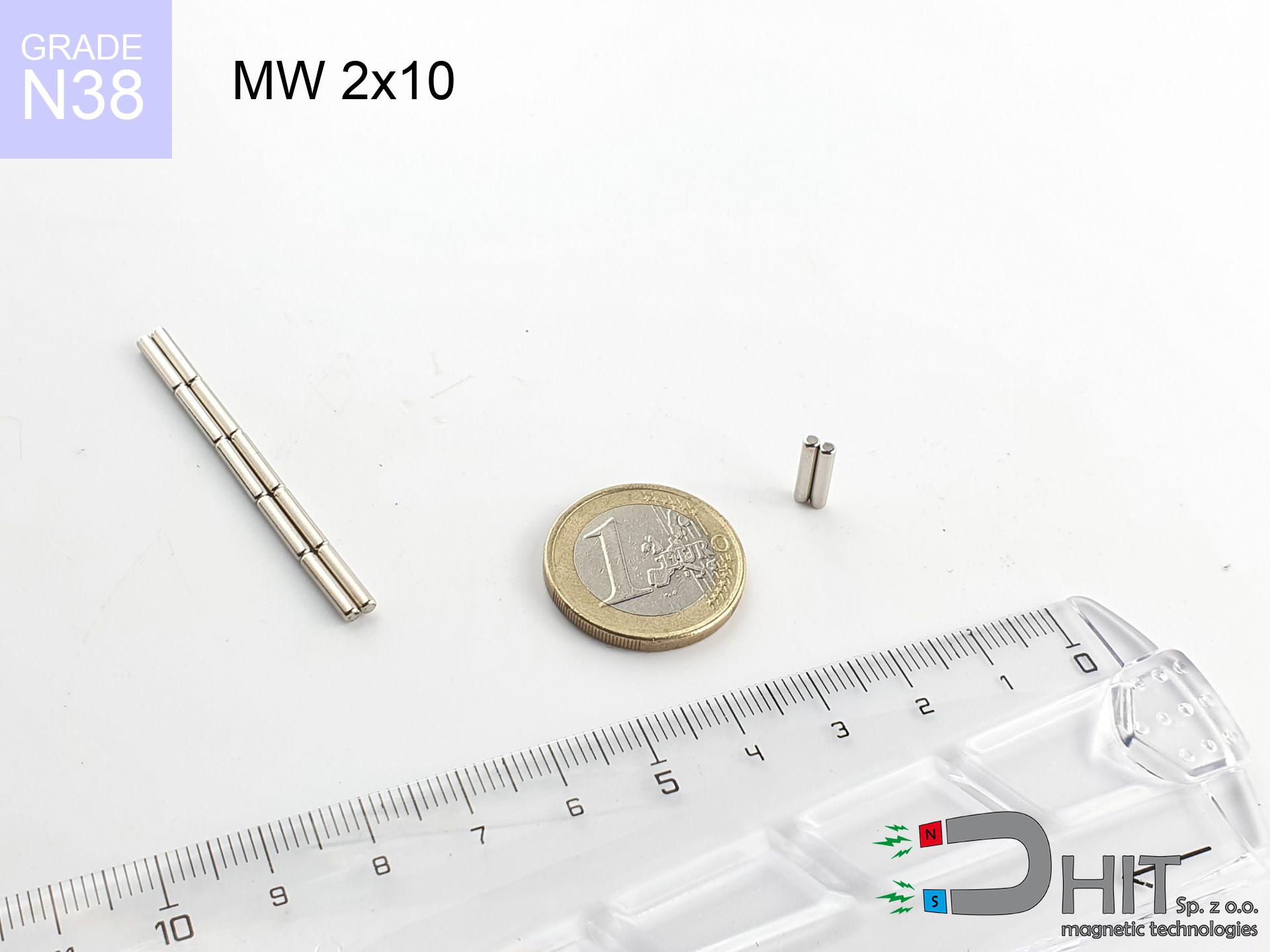
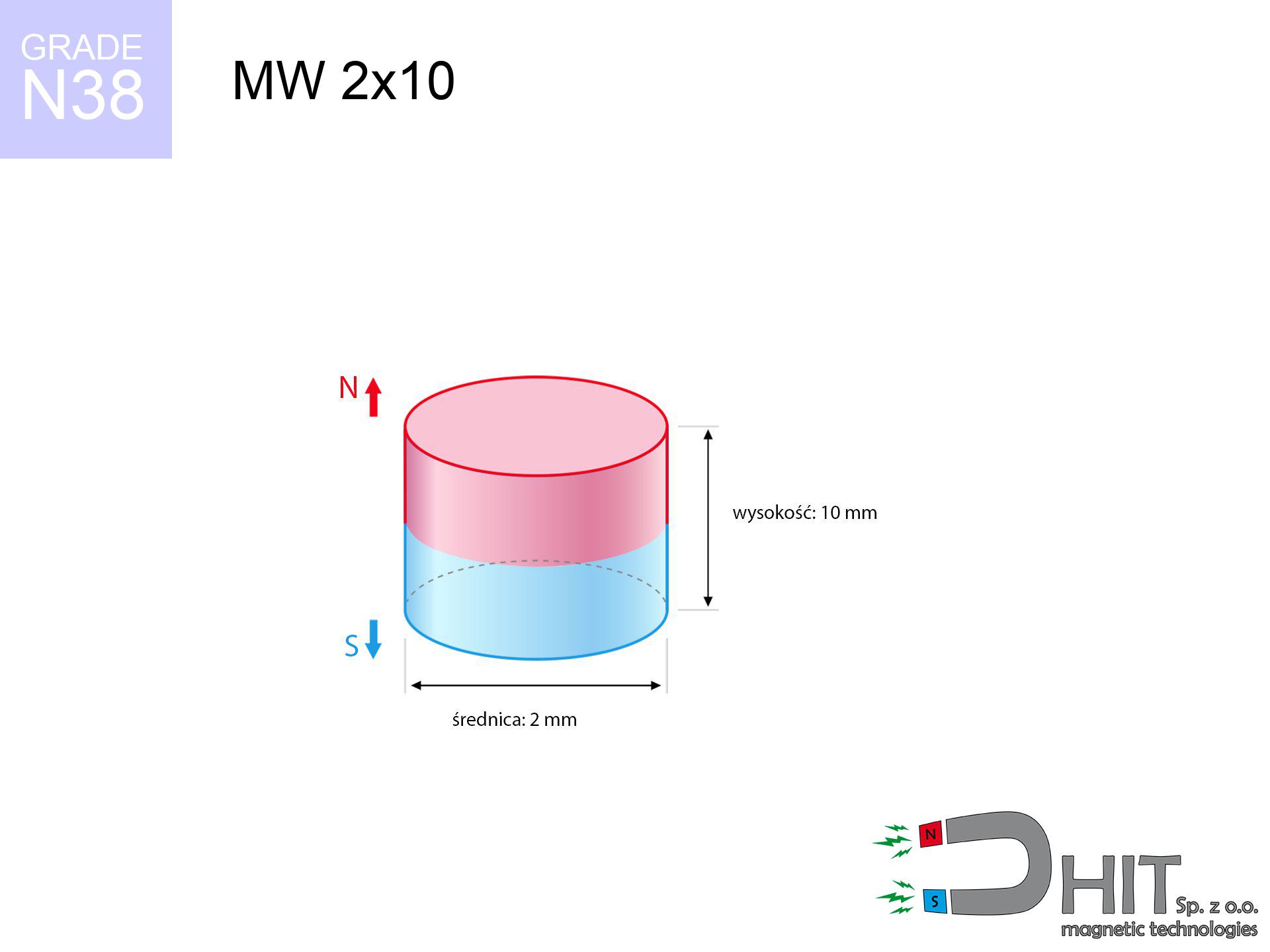
MW 2x10 / N38 - cylindrical magnet
cylindrical magnet
Catalog no 010054
GTIN/EAN: 5906301810537
- Diameter Ø
- 2 mm [±0,1 mm]
- Height
- 10 mm [±0,1 mm]
- Weight
- 0.24 g
- Magnetization Direction
- ↑ axial
- Coating
- [NiCuNi] Nickel
0.1845 zł with VAT / pcs + price for transport
0.1500 zł net + 23% VAT / pcs
bulk discounts:
Need more?Engineering report for this magnet
Full PDF analysis: pull and shear force, effect of distance, temperature and plate thickness, safety distances and the demagnetization curve.
Pick up the phone and ask
+48 22 499 98 98
alternatively drop us a message through
inquiry form
the contact form page.
Specifications and structure of magnets can be tested on our
magnetic mass calculator.
Same-day shipping for orders placed before 14:00.
Detailed specification - MW 2x10 / N38 - cylindrical magnet
Specification / characteristics - MW 2x10 / N38 - cylindrical magnet
| properties | values |
|---|---|
| Cat. no. | 010054 |
| GTIN/EAN | 5906301810537 |
| Production/Distribution | Dhit sp. z o.o. |
| Country of origin | Poland / China / Germany |
| Customs code | 85059029 |
| Diameter Ø | 2 mm [±0,1 mm] |
| Height | 10 mm [±0,1 mm] |
| Weight | 0.24 g |
| Magnetization Direction | ↑ axial |
| Load capacity ~ ? | 0.07 kg / 0.70 N |
| Magnetic Induction ~ ? | 613.08 mT / 6131 Gs |
| Coating | [NiCuNi] Nickel |
| Manufacturing Tolerance | ±0.1 mm |
Magnetic properties of material N38
| properties | values | units |
|---|---|---|
| remenance Br [min. - max.] ? | 12.2-12.6 | kGs |
| remenance Br [min. - max.] ? | 1220-1260 | mT |
| coercivity bHc ? | 10.8-11.5 | kOe |
| coercivity bHc ? | 860-915 | kA/m |
| actual internal force iHc | ≥ 12 | kOe |
| actual internal force iHc | ≥ 955 | kA/m |
| energy density [min. - max.] ? | 36-38 | BH max MGOe |
| energy density [min. - max.] ? | 287-303 | BH max KJ/m |
| max. temperature ? | ≤ 80 | °C |
Physical properties of sintered neodymium magnets Nd2Fe14B at 20°C
| properties | values | units |
|---|---|---|
| Vickers hardness | ≥550 | Hv |
| Density | ≥7.4 | g/cm3 |
| Curie Temperature TC | 312 - 380 | °C |
| Curie Temperature TF | 593 - 716 | °F |
| Specific resistance | 150 | μΩ⋅cm |
| Bending strength | 250 | MPa |
| Compressive strength | 1000~1100 | MPa |
| Thermal expansion parallel (∥) to orientation (M) | (3-4) x 10-6 | °C-1 |
| Thermal expansion perpendicular (⊥) to orientation (M) | -(1-3) x 10-6 | °C-1 |
| Young's modulus | 1.7 x 10⁴ | kg/mm² |
Technical modeling of the product - data
These information are the direct effect of a engineering calculation. Results were calculated on models for the material Nd2Fe14B. Real-world performance may deviate from the simulation results. Treat these calculations as a reference point during assembly planning.
Table 1: Static force (pull vs distance) - power drop
MW 2x10 / N38
| Distance (mm) | Induction (Gauss) / mT | Pull Force (kg/lbs/g/N) | Risk Status |
|---|---|---|---|
| 0 mm |
6107 Gs
610.7 mT
|
0.07 kg / 0.15 pounds
70.0 g / 0.7 N
|
weak grip |
| 1 mm |
1790 Gs
179.0 mT
|
0.01 kg / 0.01 pounds
6.0 g / 0.1 N
|
weak grip |
| 2 mm |
633 Gs
63.3 mT
|
0.00 kg / 0.00 pounds
0.8 g / 0.0 N
|
weak grip |
| 3 mm |
300 Gs
30.0 mT
|
0.00 kg / 0.00 pounds
0.2 g / 0.0 N
|
weak grip |
| 5 mm |
107 Gs
10.7 mT
|
0.00 kg / 0.00 pounds
0.0 g / 0.0 N
|
weak grip |
| 10 mm |
23 Gs
2.3 mT
|
0.00 kg / 0.00 pounds
0.0 g / 0.0 N
|
weak grip |
| 15 mm |
9 Gs
0.9 mT
|
0.00 kg / 0.00 pounds
0.0 g / 0.0 N
|
weak grip |
| 20 mm |
4 Gs
0.4 mT
|
0.00 kg / 0.00 pounds
0.0 g / 0.0 N
|
weak grip |
| 30 mm |
2 Gs
0.2 mT
|
0.00 kg / 0.00 pounds
0.0 g / 0.0 N
|
weak grip |
| 50 mm |
0 Gs
0.0 mT
|
0.00 kg / 0.00 pounds
0.0 g / 0.0 N
|
weak grip |
Table 2: Slippage capacity (wall)
MW 2x10 / N38
| Distance (mm) | Friction coefficient | Pull Force (kg/lbs/g/N) |
|---|---|---|
| 0 mm | Stal (~0.2) |
0.01 kg / 0.03 pounds
14.0 g / 0.1 N
|
| 1 mm | Stal (~0.2) |
0.00 kg / 0.00 pounds
2.0 g / 0.0 N
|
| 2 mm | Stal (~0.2) |
0.00 kg / 0.00 pounds
0.0 g / 0.0 N
|
| 3 mm | Stal (~0.2) |
0.00 kg / 0.00 pounds
0.0 g / 0.0 N
|
| 5 mm | Stal (~0.2) |
0.00 kg / 0.00 pounds
0.0 g / 0.0 N
|
| 10 mm | Stal (~0.2) |
0.00 kg / 0.00 pounds
0.0 g / 0.0 N
|
| 15 mm | Stal (~0.2) |
0.00 kg / 0.00 pounds
0.0 g / 0.0 N
|
| 20 mm | Stal (~0.2) |
0.00 kg / 0.00 pounds
0.0 g / 0.0 N
|
| 30 mm | Stal (~0.2) |
0.00 kg / 0.00 pounds
0.0 g / 0.0 N
|
| 50 mm | Stal (~0.2) |
0.00 kg / 0.00 pounds
0.0 g / 0.0 N
|
Table 3: Vertical assembly (sliding) - behavior on slippery surfaces
MW 2x10 / N38
| Surface type | Friction coefficient / % Mocy | Max load (kg/lbs/g/N) |
|---|---|---|
| Raw steel |
µ = 0.3
30% Nominalnej Siły
|
0.02 kg / 0.05 pounds
21.0 g / 0.2 N
|
| Painted steel (standard) |
µ = 0.2
20% Nominalnej Siły
|
0.01 kg / 0.03 pounds
14.0 g / 0.1 N
|
| Oily/slippery steel |
µ = 0.1
10% Nominalnej Siły
|
0.01 kg / 0.02 pounds
7.0 g / 0.1 N
|
| Magnet with anti-slip rubber |
µ = 0.5
50% Nominalnej Siły
|
0.04 kg / 0.08 pounds
35.0 g / 0.3 N
|
Table 4: Steel thickness (substrate influence) - power losses
MW 2x10 / N38
| Steel thickness (mm) | % power | Real pull force (kg/lbs/g/N) |
|---|---|---|
| 0.5 mm |
|
0.01 kg / 0.02 pounds
7.0 g / 0.1 N
|
| 1 mm |
|
0.02 kg / 0.04 pounds
17.5 g / 0.2 N
|
| 2 mm |
|
0.04 kg / 0.08 pounds
35.0 g / 0.3 N
|
| 3 mm |
|
0.05 kg / 0.12 pounds
52.5 g / 0.5 N
|
| 5 mm |
|
0.07 kg / 0.15 pounds
70.0 g / 0.7 N
|
| 10 mm |
|
0.07 kg / 0.15 pounds
70.0 g / 0.7 N
|
| 11 mm |
|
0.07 kg / 0.15 pounds
70.0 g / 0.7 N
|
| 12 mm |
|
0.07 kg / 0.15 pounds
70.0 g / 0.7 N
|
Table 5: Working in heat (material behavior) - resistance threshold
MW 2x10 / N38
| Ambient temp. (°C) | Power loss | Remaining pull (kg/lbs/g/N) | Status |
|---|---|---|---|
| 20 °C | 0.0% |
0.07 kg / 0.15 pounds
70.0 g / 0.7 N
|
OK |
| 40 °C | -2.2% |
0.07 kg / 0.15 pounds
68.5 g / 0.7 N
|
OK |
| 60 °C | -4.4% |
0.07 kg / 0.15 pounds
66.9 g / 0.7 N
|
OK |
| 80 °C | -6.6% |
0.07 kg / 0.14 pounds
65.4 g / 0.6 N
|
|
| 100 °C | -28.8% |
0.05 kg / 0.11 pounds
49.8 g / 0.5 N
|
Table 6: Two magnets (attraction) - field range
MW 2x10 / N38
| Gap (mm) | Attraction (kg/lbs) (N-S) | Lateral Force (kg/lbs/g/N) | Repulsion (kg/lbs) (N-N) |
|---|---|---|---|
| 0 mm |
0.72 kg / 1.59 pounds
6 130 Gs
|
0.11 kg / 0.24 pounds
108 g / 1.1 N
|
N/A |
| 1 mm |
0.22 kg / 0.49 pounds
6 799 Gs
|
0.03 kg / 0.07 pounds
34 g / 0.3 N
|
0.20 kg / 0.44 pounds
~0 Gs
|
| 2 mm |
0.06 kg / 0.14 pounds
3 581 Gs
|
0.01 kg / 0.02 pounds
9 g / 0.1 N
|
0.06 kg / 0.12 pounds
~0 Gs
|
| 3 mm |
0.02 kg / 0.04 pounds
2 036 Gs
|
0.00 kg / 0.01 pounds
3 g / 0.0 N
|
0.02 kg / 0.04 pounds
~0 Gs
|
| 5 mm |
0.00 kg / 0.01 pounds
847 Gs
|
0.00 kg / 0.00 pounds
1 g / 0.0 N
|
0.00 kg / 0.00 pounds
~0 Gs
|
| 10 mm |
0.00 kg / 0.00 pounds
213 Gs
|
0.00 kg / 0.00 pounds
0 g / 0.0 N
|
0.00 kg / 0.00 pounds
~0 Gs
|
| 20 mm |
0.00 kg / 0.00 pounds
46 Gs
|
0.00 kg / 0.00 pounds
0 g / 0.0 N
|
0.00 kg / 0.00 pounds
~0 Gs
|
| 50 mm |
0.00 kg / 0.00 pounds
5 Gs
|
0.00 kg / 0.00 pounds
0 g / 0.0 N
|
0.00 kg / 0.00 pounds
~0 Gs
|
| 60 mm |
0.00 kg / 0.00 pounds
3 Gs
|
0.00 kg / 0.00 pounds
0 g / 0.0 N
|
0.00 kg / 0.00 pounds
~0 Gs
|
| 70 mm |
0.00 kg / 0.00 pounds
2 Gs
|
0.00 kg / 0.00 pounds
0 g / 0.0 N
|
0.00 kg / 0.00 pounds
~0 Gs
|
| 80 mm |
0.00 kg / 0.00 pounds
1 Gs
|
0.00 kg / 0.00 pounds
0 g / 0.0 N
|
0.00 kg / 0.00 pounds
~0 Gs
|
| 90 mm |
0.00 kg / 0.00 pounds
1 Gs
|
0.00 kg / 0.00 pounds
0 g / 0.0 N
|
0.00 kg / 0.00 pounds
~0 Gs
|
| 100 mm |
0.00 kg / 0.00 pounds
1 Gs
|
0.00 kg / 0.00 pounds
0 g / 0.0 N
|
0.00 kg / 0.00 pounds
~0 Gs
|
Table 7: Protective zones (implants) - precautionary measures
MW 2x10 / N38
| Object / Device | Limit (Gauss) / mT | Safe distance |
|---|---|---|
| Pacemaker | 5 Gs (0.5 mT) | 2.0 cm |
| Hearing aid | 10 Gs (1.0 mT) | 1.5 cm |
| Timepiece | 20 Gs (2.0 mT) | 1.5 cm |
| Phone / Smartphone | 40 Gs (4.0 mT) | 1.0 cm |
| Car key | 50 Gs (5.0 mT) | 1.0 cm |
| Payment card | 400 Gs (40.0 mT) | 0.5 cm |
| HDD hard drive | 600 Gs (60.0 mT) | 0.5 cm |
Table 8: Dynamics (kinetic energy) - collision effects
MW 2x10 / N38
| Start from (mm) | Speed (km/h) | Energy (J) | Predicted outcome |
|---|---|---|---|
| 10 mm |
5.68 km/h
(1.58 m/s)
|
0.00 J | |
| 30 mm |
5.68 km/h
(1.58 m/s)
|
0.00 J | |
| 50 mm |
5.68 km/h
(1.58 m/s)
|
0.00 J | |
| 100 mm |
5.68 km/h
(1.58 m/s)
|
0.00 J |
Table 9: Surface protection spec
MW 2x10 / N38
| Technical parameter | Value / Description |
|---|---|
| Coating type | [NiCuNi] Nickel |
| Layer structure | Nickel - Copper - Nickel |
| Layer thickness | 10-20 µm |
| Salt spray test (SST) ? | 24 h |
| Recommended environment | Indoors only (dry) |
Table 10: Electrical data (Pc)
MW 2x10 / N38
| Parameter | Value | SI Unit / Description |
|---|---|---|
| Magnetic Flux | 232 Mx | 2.3 µWb |
| Pc Coefficient | 1.55 | High (Stable) |
Table 11: Physics of underwater searching
MW 2x10 / N38
| Environment | Effective steel pull | Effect |
|---|---|---|
| Air (land) | 0.07 kg | Standard |
| Water (riverbed) |
0.08 kg
(+0.01 kg buoyancy gain)
|
+14.5% |
1. Vertical hold
*Warning: On a vertical surface, the magnet holds merely ~20% of its nominal pull.
2. Plate thickness effect
*Thin metal sheet (e.g. 0.5mm PC case) drastically limits the holding force.
3. Thermal stability
*For N38 material, the safety limit is 80°C.
4. Demagnetization curve and operating point (B-H)
chart generated for the permeance coefficient Pc (Permeance Coefficient) = 1.55
The chart above illustrates the magnetic characteristics of the material within the second quadrant of the hysteresis loop. The solid red line represents the demagnetization curve (material potential), while the dashed blue line is the load line based on the magnet's geometry. The Pc (Permeance Coefficient), also known as the load line slope, is a dimensionless value that describes the relationship between the magnet's shape and its magnetic stability. The intersection of these two lines (the black dot) is the operating point — it determines the actual magnetic flux density generated by the magnet in this specific configuration. A higher Pc value means the magnet is more 'slender' (tall relative to its area), resulting in a higher operating point and better resistance to irreversible demagnetization caused by external fields or temperature. A value of 0.42 is relatively low (typical for flat magnets), meaning the operating point is closer to the 'knee' of the curve — caution is advised when operating at temperatures near the maximum limit to avoid strength loss.
Chemical composition
| iron (Fe) | 64% – 68% |
| neodymium (Nd) | 29% – 32% |
| boron (B) | 1.1% – 1.2% |
| dysprosium (Dy) | 0.5% – 2.0% |
| coating (Ni-Cu-Ni) | < 0.05% |
Ecology and recycling (GPSR)
| recyclability (EoL) | 100% |
| recycled raw materials | ~10% (pre-cons) |
| carbon footprint | low / zredukowany |
| waste code (EWC) | 16 02 16 |
View more proposals


Pros and cons of Nd2Fe14B magnets.
Advantages
- They do not lose power, even during nearly ten years – the decrease in strength is only ~1% (theoretically),
- They are extremely resistant to demagnetization induced by presence of other magnetic fields,
- Thanks to the metallic finish, the coating of nickel, gold, or silver-plated gives an clean appearance,
- They show high magnetic induction at the operating surface, which increases their power,
- Through (adequate) combination of ingredients, they can achieve high thermal strength, allowing for functioning at temperatures approaching 230°C and above...
- Thanks to flexibility in shaping and the capacity to adapt to complex applications,
- Significant place in innovative solutions – they are commonly used in mass storage devices, electromotive mechanisms, diagnostic systems, as well as complex engineering applications.
- Compactness – despite small sizes they generate large force, making them ideal for precision applications
Limitations
- They are prone to damage upon heavy impacts. To avoid cracks, it is worth securing magnets using a steel holder. Such protection not only shields the magnet but also improves its resistance to damage
- When exposed to high temperature, neodymium magnets suffer a drop in power. Often, when the temperature exceeds 80°C, their power decreases (depending on the size and shape of the magnet). For those who need magnets for extreme conditions, we offer [AH] versions withstanding up to 230°C
- When exposed to humidity, magnets usually rust. For applications outside, it is recommended to use protective magnets, such as those in rubber or plastics, which secure oxidation and corrosion.
- Due to limitations in realizing threads and complicated forms in magnets, we recommend using cover - magnetic mount.
- Potential hazard resulting from small fragments of magnets are risky, in case of ingestion, which becomes key in the context of child safety. Furthermore, tiny parts of these products can complicate diagnosis medical in case of swallowing.
- Higher cost of purchase is one of the disadvantages compared to ceramic magnets, especially in budget applications
Holding force characteristics
Maximum lifting force for a neodymium magnet – what it depends on?
- with the use of a yoke made of low-carbon steel, ensuring full magnetic saturation
- possessing a thickness of at least 10 mm to ensure full flux closure
- with an ground touching surface
- without any insulating layer between the magnet and steel
- for force applied at a right angle (in the magnet axis)
- in temp. approx. 20°C
Lifting capacity in real conditions – factors
- Distance (between the magnet and the metal), since even a tiny clearance (e.g. 0.5 mm) can cause a reduction in force by up to 50% (this also applies to varnish, corrosion or dirt).
- Load vector – maximum parameter is available only during pulling at a 90° angle. The shear force of the magnet along the surface is usually many times smaller (approx. 1/5 of the lifting capacity).
- Substrate thickness – for full efficiency, the steel must be adequately massive. Thin sheet limits the attraction force (the magnet "punches through" it).
- Chemical composition of the base – mild steel attracts best. Alloy admixtures decrease magnetic permeability and lifting capacity.
- Smoothness – ideal contact is possible only on polished steel. Any scratches and bumps reduce the real contact area, weakening the magnet.
- Temperature influence – hot environment weakens pulling force. Exceeding the limit temperature can permanently damage the magnet.
Lifting capacity testing was carried out on a smooth plate of optimal thickness, under perpendicular forces, in contrast under shearing force the lifting capacity is smaller. In addition, even a slight gap between the magnet’s surface and the plate reduces the load capacity.
Safe handling of NdFeB magnets
Risk of cracking
Despite metallic appearance, the material is brittle and cannot withstand shocks. Do not hit, as the magnet may crumble into sharp, dangerous pieces.
GPS Danger
Navigation devices and mobile phones are extremely susceptible to magnetism. Close proximity with a powerful NdFeB magnet can permanently damage the sensors in your phone.
Avoid contact if allergic
Certain individuals experience a sensitization to Ni, which is the common plating for NdFeB magnets. Prolonged contact may cause a rash. We strongly advise use safety gloves.
Life threat
For implant holders: Strong magnetic fields disrupt medical devices. Keep at least 30 cm distance or ask another person to handle the magnets.
Threat to electronics
Intense magnetic fields can erase data on credit cards, HDDs, and other magnetic media. Stay away of at least 10 cm.
Danger to the youngest
Strictly keep magnets away from children. Ingestion danger is significant, and the consequences of magnets clamping inside the body are life-threatening.
Handling rules
Use magnets consciously. Their powerful strength can surprise even professionals. Plan your moves and do not underestimate their force.
Fire risk
Dust produced during cutting of magnets is flammable. Do not drill into magnets without proper cooling and knowledge.
Crushing risk
Pinching hazard: The attraction force is so immense that it can result in blood blisters, crushing, and broken bones. Protective gloves are recommended.
Thermal limits
Keep cool. Neodymium magnets are susceptible to heat. If you need operation above 80°C, inquire about HT versions (H, SH, UH).
Tabela kosztu i czasu dostawy
Płatność przed wysyłką:

GLS kurier
Przesyłka będzie u Ciebie za 2-3 dni
14.99 ZŁ

InPost Paczkomaty 24/7
Przesyłka będzie u Ciebie za 1-2 dni
12.30 ZŁ
Płatność przy odbiorze (pobranie):
GLS kurier
Przesyłka będzie u Ciebie za 1-2 dni
23.00 ZŁ
Rate the product
Your rating