
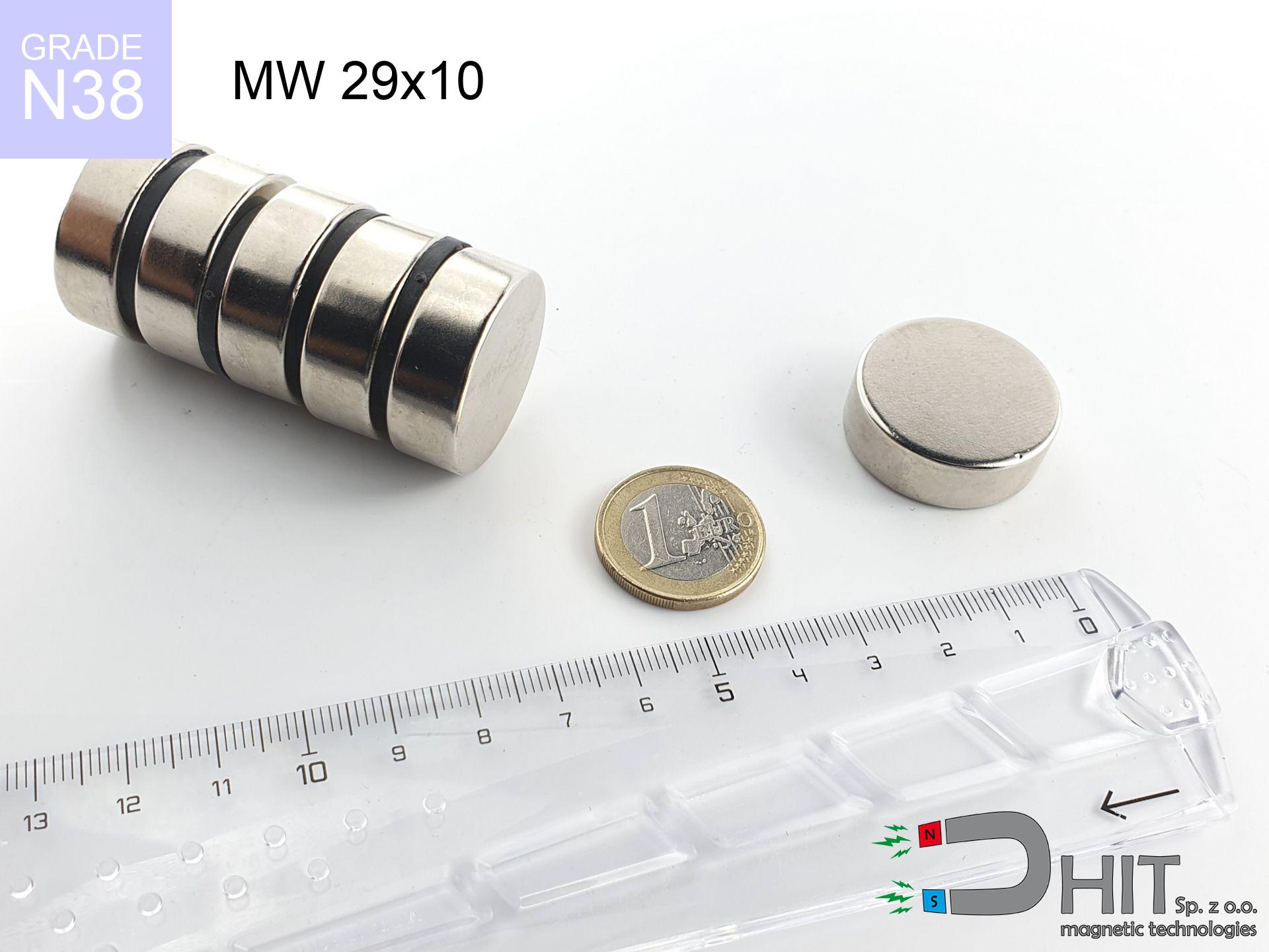
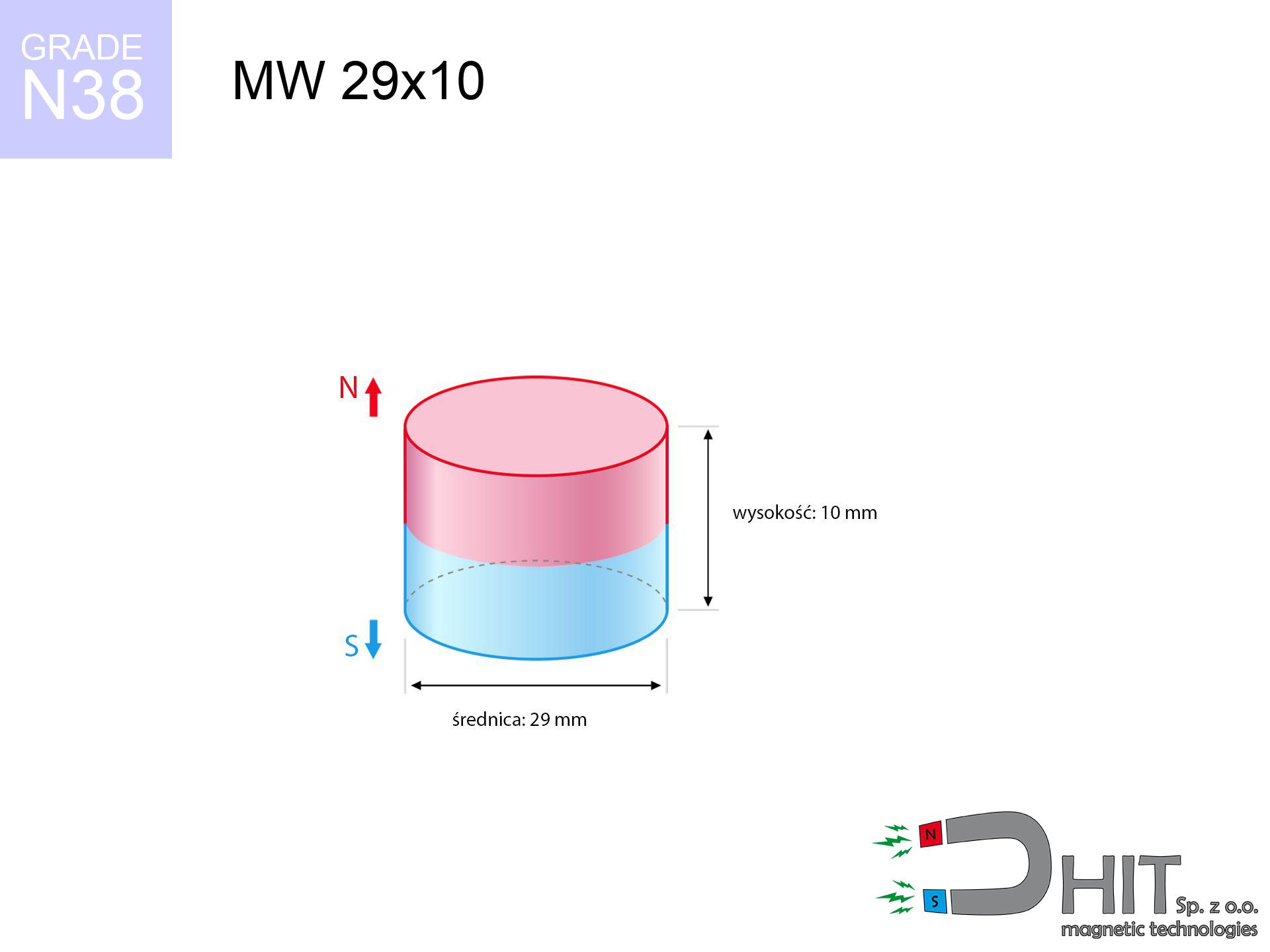
MW 29x10 / N38 - cylindrical magnet
cylindrical magnet
Catalog no 010053
GTIN/EAN: 5906301810520
- Diameter Ø
- 29 mm [±0,1 mm]
- Height
- 10 mm [±0,1 mm]
- Weight
- 49.54 g
- Magnetization Direction
- ↑ axial
- Coating
- [NiCuNi] Nickel
17.34 zł with VAT / pcs + price for transport
14.10 zł net + 23% VAT / pcs
bulk discounts:
Need more?Engineering report for this magnet
Full PDF analysis: pull and shear force, effect of distance, temperature and plate thickness, safety distances and the demagnetization curve.
Call us now
+48 888 99 98 98
if you prefer get in touch through
our online form
the contact section.
Parameters along with shape of neodymium magnets can be analyzed using our
force calculator.
Order by 14:00 and we’ll ship today!
Technical of the product - MW 29x10 / N38 - cylindrical magnet
Specification / characteristics - MW 29x10 / N38 - cylindrical magnet
| properties | values |
|---|---|
| Cat. no. | 010053 |
| GTIN/EAN | 5906301810520 |
| Production/Distribution | Dhit sp. z o.o. |
| Country of origin | Poland / China / Germany |
| Customs code | 85059029 |
| Diameter Ø | 29 mm [±0,1 mm] |
| Height | 10 mm [±0,1 mm] |
| Weight | 49.54 g |
| Magnetization Direction | ↑ axial |
| Load capacity ~ ? | 20.82 kg / 204.22 N |
| Magnetic Induction ~ ? | 351.88 mT / 3519 Gs |
| Coating | [NiCuNi] Nickel |
| Manufacturing Tolerance | ±0.1 mm |
Magnetic properties of material N38
| properties | values | units |
|---|---|---|
| remenance Br [min. - max.] ? | 12.2-12.6 | kGs |
| remenance Br [min. - max.] ? | 1220-1260 | mT |
| coercivity bHc ? | 10.8-11.5 | kOe |
| coercivity bHc ? | 860-915 | kA/m |
| actual internal force iHc | ≥ 12 | kOe |
| actual internal force iHc | ≥ 955 | kA/m |
| energy density [min. - max.] ? | 36-38 | BH max MGOe |
| energy density [min. - max.] ? | 287-303 | BH max KJ/m |
| max. temperature ? | ≤ 80 | °C |
Physical properties of sintered neodymium magnets Nd2Fe14B at 20°C
| properties | values | units |
|---|---|---|
| Vickers hardness | ≥550 | Hv |
| Density | ≥7.4 | g/cm3 |
| Curie Temperature TC | 312 - 380 | °C |
| Curie Temperature TF | 593 - 716 | °F |
| Specific resistance | 150 | μΩ⋅cm |
| Bending strength | 250 | MPa |
| Compressive strength | 1000~1100 | MPa |
| Thermal expansion parallel (∥) to orientation (M) | (3-4) x 10-6 | °C-1 |
| Thermal expansion perpendicular (⊥) to orientation (M) | -(1-3) x 10-6 | °C-1 |
| Young's modulus | 1.7 x 10⁴ | kg/mm² |
Technical simulation of the product - technical parameters
The following information are the outcome of a engineering calculation. Results were calculated on models for the class Nd2Fe14B. Actual conditions may deviate from the simulation results. Treat these calculations as a reference point when designing systems.
Table 1: Static pull force (force vs distance) - interaction chart
MW 29x10 / N38
| Distance (mm) | Induction (Gauss) / mT | Pull Force (kg/lbs/g/N) | Risk Status |
|---|---|---|---|
| 0 mm |
3518 Gs
351.8 mT
|
20.82 kg / 45.90 lbs
20820.0 g / 204.2 N
|
dangerous! |
| 1 mm |
3321 Gs
332.1 mT
|
18.55 kg / 40.89 lbs
18548.8 g / 182.0 N
|
dangerous! |
| 2 mm |
3106 Gs
310.6 mT
|
16.23 kg / 35.77 lbs
16226.1 g / 159.2 N
|
dangerous! |
| 3 mm |
2883 Gs
288.3 mT
|
13.98 kg / 30.82 lbs
13978.2 g / 137.1 N
|
dangerous! |
| 5 mm |
2437 Gs
243.7 mT
|
9.99 kg / 22.02 lbs
9987.1 g / 98.0 N
|
warning |
| 10 mm |
1500 Gs
150.0 mT
|
3.78 kg / 8.34 lbs
3783.1 g / 37.1 N
|
warning |
| 15 mm |
905 Gs
90.5 mT
|
1.38 kg / 3.04 lbs
1379.2 g / 13.5 N
|
safe |
| 20 mm |
563 Gs
56.3 mT
|
0.53 kg / 1.17 lbs
532.4 g / 5.2 N
|
safe |
| 30 mm |
247 Gs
24.7 mT
|
0.10 kg / 0.23 lbs
102.4 g / 1.0 N
|
safe |
| 50 mm |
72 Gs
7.2 mT
|
0.01 kg / 0.02 lbs
8.7 g / 0.1 N
|
safe |
Table 2: Sliding capacity (wall)
MW 29x10 / N38
| Distance (mm) | Friction coefficient | Pull Force (kg/lbs/g/N) |
|---|---|---|
| 0 mm | Stal (~0.2) |
4.16 kg / 9.18 lbs
4164.0 g / 40.8 N
|
| 1 mm | Stal (~0.2) |
3.71 kg / 8.18 lbs
3710.0 g / 36.4 N
|
| 2 mm | Stal (~0.2) |
3.25 kg / 7.16 lbs
3246.0 g / 31.8 N
|
| 3 mm | Stal (~0.2) |
2.80 kg / 6.16 lbs
2796.0 g / 27.4 N
|
| 5 mm | Stal (~0.2) |
2.00 kg / 4.40 lbs
1998.0 g / 19.6 N
|
| 10 mm | Stal (~0.2) |
0.76 kg / 1.67 lbs
756.0 g / 7.4 N
|
| 15 mm | Stal (~0.2) |
0.28 kg / 0.61 lbs
276.0 g / 2.7 N
|
| 20 mm | Stal (~0.2) |
0.11 kg / 0.23 lbs
106.0 g / 1.0 N
|
| 30 mm | Stal (~0.2) |
0.02 kg / 0.04 lbs
20.0 g / 0.2 N
|
| 50 mm | Stal (~0.2) |
0.00 kg / 0.00 lbs
2.0 g / 0.0 N
|
Table 3: Wall mounting (shearing) - vertical pull
MW 29x10 / N38
| Surface type | Friction coefficient / % Mocy | Max load (kg/lbs/g/N) |
|---|---|---|
| Raw steel |
µ = 0.3
30% Nominalnej Siły
|
6.25 kg / 13.77 lbs
6246.0 g / 61.3 N
|
| Painted steel (standard) |
µ = 0.2
20% Nominalnej Siły
|
4.16 kg / 9.18 lbs
4164.0 g / 40.8 N
|
| Oily/slippery steel |
µ = 0.1
10% Nominalnej Siły
|
2.08 kg / 4.59 lbs
2082.0 g / 20.4 N
|
| Magnet with anti-slip rubber |
µ = 0.5
50% Nominalnej Siły
|
10.41 kg / 22.95 lbs
10410.0 g / 102.1 N
|
Table 4: Steel thickness (substrate influence) - power losses
MW 29x10 / N38
| Steel thickness (mm) | % power | Real pull force (kg/lbs/g/N) |
|---|---|---|
| 0.5 mm |
|
1.04 kg / 2.30 lbs
1041.0 g / 10.2 N
|
| 1 mm |
|
2.60 kg / 5.74 lbs
2602.5 g / 25.5 N
|
| 2 mm |
|
5.21 kg / 11.48 lbs
5205.0 g / 51.1 N
|
| 3 mm |
|
7.81 kg / 17.21 lbs
7807.5 g / 76.6 N
|
| 5 mm |
|
13.01 kg / 28.69 lbs
13012.5 g / 127.7 N
|
| 10 mm |
|
20.82 kg / 45.90 lbs
20820.0 g / 204.2 N
|
| 11 mm |
|
20.82 kg / 45.90 lbs
20820.0 g / 204.2 N
|
| 12 mm |
|
20.82 kg / 45.90 lbs
20820.0 g / 204.2 N
|
Table 5: Thermal stability (material behavior) - thermal limit
MW 29x10 / N38
| Ambient temp. (°C) | Power loss | Remaining pull (kg/lbs/g/N) | Status |
|---|---|---|---|
| 20 °C | 0.0% |
20.82 kg / 45.90 lbs
20820.0 g / 204.2 N
|
OK |
| 40 °C | -2.2% |
20.36 kg / 44.89 lbs
20362.0 g / 199.8 N
|
OK |
| 60 °C | -4.4% |
19.90 kg / 43.88 lbs
19903.9 g / 195.3 N
|
|
| 80 °C | -6.6% |
19.45 kg / 42.87 lbs
19445.9 g / 190.8 N
|
|
| 100 °C | -28.8% |
14.82 kg / 32.68 lbs
14823.8 g / 145.4 N
|
Table 6: Magnet-Magnet interaction (repulsion) - field range
MW 29x10 / N38
| Gap (mm) | Attraction (kg/lbs) (N-S) | Lateral Force (kg/lbs/g/N) | Repulsion (kg/lbs) (N-N) |
|---|---|---|---|
| 0 mm |
50.40 kg / 111.11 lbs
5 016 Gs
|
7.56 kg / 16.67 lbs
7560 g / 74.2 N
|
N/A |
| 1 mm |
47.70 kg / 105.17 lbs
6 845 Gs
|
7.16 kg / 15.78 lbs
7156 g / 70.2 N
|
42.93 kg / 94.65 lbs
~0 Gs
|
| 2 mm |
44.90 kg / 98.99 lbs
6 641 Gs
|
6.74 kg / 14.85 lbs
6735 g / 66.1 N
|
40.41 kg / 89.09 lbs
~0 Gs
|
| 3 mm |
42.08 kg / 92.77 lbs
6 429 Gs
|
6.31 kg / 13.92 lbs
6312 g / 61.9 N
|
37.87 kg / 83.50 lbs
~0 Gs
|
| 5 mm |
36.52 kg / 80.52 lbs
5 990 Gs
|
5.48 kg / 12.08 lbs
5478 g / 53.7 N
|
32.87 kg / 72.47 lbs
~0 Gs
|
| 10 mm |
24.18 kg / 53.30 lbs
4 873 Gs
|
3.63 kg / 7.99 lbs
3626 g / 35.6 N
|
21.76 kg / 47.97 lbs
~0 Gs
|
| 20 mm |
9.16 kg / 20.19 lbs
2 999 Gs
|
1.37 kg / 3.03 lbs
1374 g / 13.5 N
|
8.24 kg / 18.17 lbs
~0 Gs
|
| 50 mm |
0.54 kg / 1.19 lbs
729 Gs
|
0.08 kg / 0.18 lbs
81 g / 0.8 N
|
0.49 kg / 1.07 lbs
~0 Gs
|
| 60 mm |
0.25 kg / 0.55 lbs
493 Gs
|
0.04 kg / 0.08 lbs
37 g / 0.4 N
|
0.22 kg / 0.49 lbs
~0 Gs
|
| 70 mm |
0.12 kg / 0.27 lbs
347 Gs
|
0.02 kg / 0.04 lbs
18 g / 0.2 N
|
0.11 kg / 0.24 lbs
~0 Gs
|
| 80 mm |
0.06 kg / 0.14 lbs
252 Gs
|
0.01 kg / 0.02 lbs
10 g / 0.1 N
|
0.06 kg / 0.13 lbs
~0 Gs
|
| 90 mm |
0.04 kg / 0.08 lbs
188 Gs
|
0.01 kg / 0.01 lbs
5 g / 0.1 N
|
0.03 kg / 0.07 lbs
~0 Gs
|
| 100 mm |
0.02 kg / 0.05 lbs
144 Gs
|
0.00 kg / 0.01 lbs
3 g / 0.0 N
|
0.02 kg / 0.04 lbs
~0 Gs
|
Table 7: Protective zones (implants) - warnings
MW 29x10 / N38
| Object / Device | Limit (Gauss) / mT | Safe distance |
|---|---|---|
| Pacemaker | 5 Gs (0.5 mT) | 13.5 cm |
| Hearing aid | 10 Gs (1.0 mT) | 10.5 cm |
| Mechanical watch | 20 Gs (2.0 mT) | 8.5 cm |
| Mobile device | 40 Gs (4.0 mT) | 6.5 cm |
| Remote | 50 Gs (5.0 mT) | 6.0 cm |
| Payment card | 400 Gs (40.0 mT) | 2.5 cm |
| HDD hard drive | 600 Gs (60.0 mT) | 2.0 cm |
Table 8: Dynamics (cracking risk) - warning
MW 29x10 / N38
| Start from (mm) | Speed (km/h) | Energy (J) | Predicted outcome |
|---|---|---|---|
| 10 mm |
23.58 km/h
(6.55 m/s)
|
1.06 J | |
| 30 mm |
25.55 km/h
(7.10 m/s)
|
1.25 J | |
| 50 mm |
25.62 km/h
(7.12 m/s)
|
1.25 J | |
| 100 mm |
25.63 km/h
(7.12 m/s)
|
1.26 J |
Table 9: Surface protection spec
MW 29x10 / N38
| Technical parameter | Value / Description |
|---|---|
| Coating type | [NiCuNi] Nickel |
| Layer structure | Nickel - Copper - Nickel |
| Layer thickness | 10-20 µm |
| Salt spray test (SST) ? | 24 h |
| Recommended environment | Indoors only (dry) |
Table 10: Construction data (Pc)
MW 29x10 / N38
| Parameter | Value | SI Unit / Description |
|---|---|---|
| Magnetic Flux | 24 471 Mx | 244.7 µWb |
| Pc Coefficient | 0.45 | Low (Flat) |
Table 11: Hydrostatics and buoyancy
MW 29x10 / N38
| Environment | Effective steel pull | Effect |
|---|---|---|
| Air (land) | 20.82 kg | Standard |
| Water (riverbed) |
23.84 kg
(+3.02 kg buoyancy gain)
|
+14.5% |
1. Sliding resistance
*Warning: On a vertical surface, the magnet holds only ~20% of its max power.
2. Plate thickness effect
*Thin steel (e.g. 0.5mm PC case) drastically reduces the holding force.
3. Heat tolerance
*For N38 grade, the critical limit is 80°C.
4. Demagnetization curve and operating point (B-H)
chart generated for the permeance coefficient Pc (Permeance Coefficient) = 0.45
The chart above illustrates the magnetic characteristics of the material within the second quadrant of the hysteresis loop. The solid red line represents the demagnetization curve (material potential), while the dashed blue line is the load line based on the magnet's geometry. The Pc (Permeance Coefficient), also known as the load line slope, is a dimensionless value that describes the relationship between the magnet's shape and its magnetic stability. The intersection of these two lines (the black dot) is the operating point — it determines the actual magnetic flux density generated by the magnet in this specific configuration. A higher Pc value means the magnet is more 'slender' (tall relative to its area), resulting in a higher operating point and better resistance to irreversible demagnetization caused by external fields or temperature. A value of 0.42 is relatively low (typical for flat magnets), meaning the operating point is closer to the 'knee' of the curve — caution is advised when operating at temperatures near the maximum limit to avoid strength loss.
Material specification
| iron (Fe) | 64% – 68% |
| neodymium (Nd) | 29% – 32% |
| boron (B) | 1.1% – 1.2% |
| dysprosium (Dy) | 0.5% – 2.0% |
| coating (Ni-Cu-Ni) | < 0.05% |
Environmental data
| recyclability (EoL) | 100% |
| recycled raw materials | ~10% (pre-cons) |
| carbon footprint | low / zredukowany |
| waste code (EWC) | 16 02 16 |
Other offers
![SM 25x300 [2xM8] / N52 - magnetic separator](https://cdn3.dhit.pl/graphics/products/sm-25x300-2xm8-dij.jpg "SM 25x300 [2xM8] / N52 - magnetic separator")


Strengths and weaknesses of rare earth magnets.
Strengths
- Their magnetic field is durable, and after around ten years it decreases only by ~1% (according to research),
- They are extremely resistant to demagnetization induced by presence of other magnetic fields,
- Thanks to the reflective finish, the coating of nickel, gold, or silver gives an modern appearance,
- The surface of neodymium magnets generates a intense magnetic field – this is a key feature,
- Made from properly selected components, these magnets show impressive resistance to high heat, enabling them to function (depending on their form) at temperatures up to 230°C and above...
- Possibility of exact creating and adjusting to defined applications,
- Universal use in modern industrial fields – they are used in data components, brushless drives, medical devices, also technologically advanced constructions.
- Relatively small size with high pulling force – neodymium magnets offer high power in tiny dimensions, which makes them useful in small systems
Disadvantages
- To avoid cracks upon strong impacts, we recommend using special steel housings. Such a solution secures the magnet and simultaneously increases its durability.
- We warn that neodymium magnets can reduce their power at high temperatures. To prevent this, we suggest our specialized [AH] magnets, which work effectively even at 230°C.
- Magnets exposed to a humid environment can corrode. Therefore while using outdoors, we advise using waterproof magnets made of rubber, plastic or other material protecting against moisture
- Due to limitations in realizing nuts and complicated shapes in magnets, we recommend using a housing - magnetic mechanism.
- Possible danger to health – tiny shards of magnets can be dangerous, when accidentally swallowed, which gains importance in the aspect of protecting the youngest. It is also worth noting that small components of these magnets can be problematic in diagnostics medical after entering the body.
- High unit price – neodymium magnets have a higher price than other types of magnets (e.g. ferrite), which hinders application in large quantities
Pull force analysis
Maximum lifting capacity of the magnet – what affects it?
- using a base made of high-permeability steel, acting as a magnetic yoke
- whose transverse dimension is min. 10 mm
- characterized by smoothness
- without the slightest clearance between the magnet and steel
- under perpendicular force vector (90-degree angle)
- in temp. approx. 20°C
Determinants of lifting force in real conditions
- Clearance – existence of any layer (rust, dirt, air) acts as an insulator, which lowers power rapidly (even by 50% at 0.5 mm).
- Pull-off angle – note that the magnet holds strongest perpendicularly. Under shear forces, the holding force drops drastically, often to levels of 20-30% of the maximum value.
- Base massiveness – insufficiently thick steel does not accept the full field, causing part of the flux to be wasted into the air.
- Material type – the best choice is pure iron steel. Hardened steels may attract less.
- Surface condition – smooth surfaces guarantee perfect abutment, which increases field saturation. Uneven metal weaken the grip.
- Temperature – heating the magnet results in weakening of force. Check the thermal limit for a given model.
Lifting capacity testing was performed on plates with a smooth surface of optimal thickness, under a perpendicular pulling force, however under shearing force the holding force is lower. Additionally, even a slight gap between the magnet and the plate lowers the load capacity.
H&S for magnets
Swallowing risk
Absolutely store magnets away from children. Ingestion danger is significant, and the consequences of magnets connecting inside the body are life-threatening.
Permanent damage
Control the heat. Heating the magnet above 80 degrees Celsius will ruin its magnetic structure and strength.
Magnetic media
Avoid bringing magnets close to a wallet, laptop, or TV. The magnetic field can destroy these devices and erase data from cards.
Pacemakers
Individuals with a ICD have to maintain an large gap from magnets. The magnetic field can disrupt the functioning of the life-saving device.
Keep away from electronics
GPS units and mobile phones are highly sensitive to magnetic fields. Close proximity with a powerful NdFeB magnet can ruin the internal compass in your phone.
Hand protection
Danger of trauma: The attraction force is so immense that it can cause hematomas, pinching, and even bone fractures. Protective gloves are recommended.
Fire risk
Fire warning: Neodymium dust is explosive. Do not process magnets in home conditions as this may cause fire.
Skin irritation risks
It is widely known that nickel (the usual finish) is a potent allergen. If your skin reacts to metals, prevent direct skin contact or opt for versions in plastic housing.
Fragile material
NdFeB magnets are sintered ceramics, meaning they are prone to chipping. Clashing of two magnets leads to them breaking into shards.
Immense force
Before use, check safety instructions. Sudden snapping can break the magnet or injure your hand. Be predictive.
Tabela kosztu i czasu dostawy
Płatność przed wysyłką:

GLS kurier
Przesyłka będzie u Ciebie za 2-3 dni
14.99 ZŁ

InPost Paczkomaty 24/7
Przesyłka będzie u Ciebie za 1-2 dni
12.30 ZŁ
Płatność przy odbiorze (pobranie):
GLS kurier
Przesyłka będzie u Ciebie za 1-2 dni
23.00 ZŁ
Rate the product
Your rating