
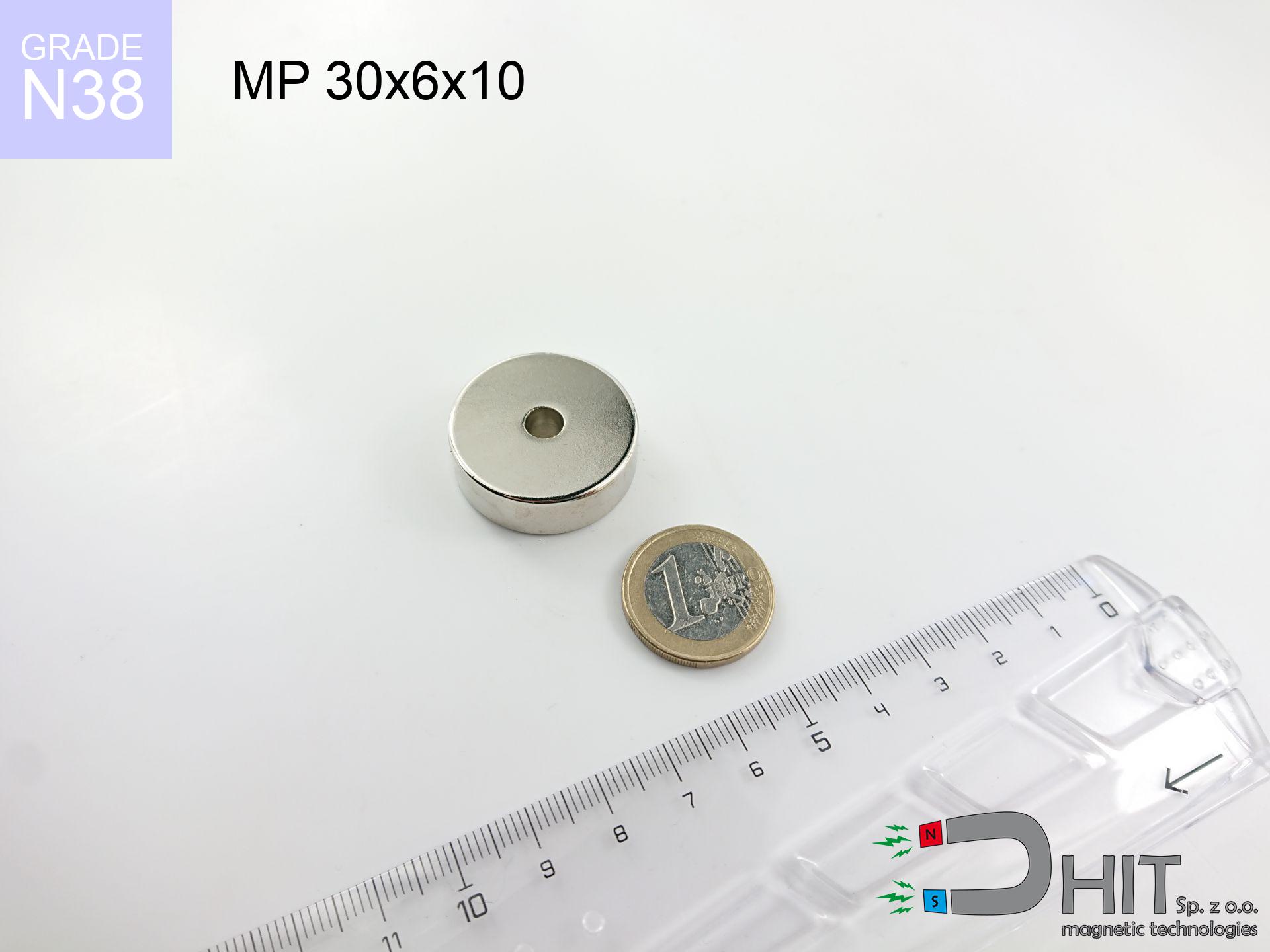
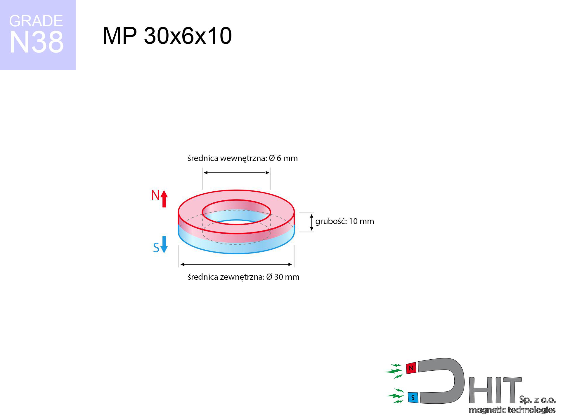
MP 30x6x10 / N38 - ring magnet
ring magnet
Catalog no 030197
GTIN/EAN: 5906301812142
Diameter
30 mm [±0,1 mm]
internal diameter Ø
6 mm [±0,1 mm]
Height
10 mm [±0,1 mm]
Weight
50.89 g
Magnetization Direction
↑ axial
Load capacity
20.71 kg / 203.16 N
Magnetic Induction
343.81 mT / 3438 Gs
Coating
[NiCuNi] Nickel
16.00 ZŁ with VAT / pcs + price for transport
13.01 ZŁ net + 23% VAT / pcs
bulk discounts:
Need more?Engineering report for this magnet
Full PDF analysis: pull and shear force, effect of distance, temperature and plate thickness, safety distances and the demagnetization curve.
Give us a call
+48 888 99 98 98
if you prefer send us a note via
our online form
the contact page.
Specifications as well as structure of a magnet can be tested using our
online calculation tool.
Orders placed before 14:00 will be shipped the same business day.
Technical specification of the product - MP 30x6x10 / N38 - ring magnet
Specification / characteristics - MP 30x6x10 / N38 - ring magnet
| properties | values |
|---|---|
| Cat. no. | 030197 |
| GTIN/EAN | 5906301812142 |
| Production/Distribution | Dhit sp. z o.o. |
| Country of origin | Poland / China / Germany |
| Customs code | 85059029 |
| Diameter | 30 mm [±0,1 mm] |
| internal diameter Ø | 6 mm [±0,1 mm] |
| Height | 10 mm [±0,1 mm] |
| Weight | 50.89 g |
| Magnetization Direction | ↑ axial |
| Load capacity ~ ? | 20.71 kg / 203.16 N |
| Magnetic Induction ~ ? | 343.81 mT / 3438 Gs |
| Coating | [NiCuNi] Nickel |
| Manufacturing Tolerance | ±0.1 mm |
Magnetic properties of material N38
| properties | values | units |
|---|---|---|
| remenance Br [min. - max.] ? | 12.2-12.6 | kGs |
| remenance Br [min. - max.] ? | 1220-1260 | mT |
| coercivity bHc ? | 10.8-11.5 | kOe |
| coercivity bHc ? | 860-915 | kA/m |
| actual internal force iHc | ≥ 12 | kOe |
| actual internal force iHc | ≥ 955 | kA/m |
| energy density [min. - max.] ? | 36-38 | BH max MGOe |
| energy density [min. - max.] ? | 287-303 | BH max KJ/m |
| max. temperature ? | ≤ 80 | °C |
Physical properties of sintered neodymium magnets Nd2Fe14B at 20°C
| properties | values | units |
|---|---|---|
| Vickers hardness | ≥550 | Hv |
| Density | ≥7.4 | g/cm3 |
| Curie Temperature TC | 312 - 380 | °C |
| Curie Temperature TF | 593 - 716 | °F |
| Specific resistance | 150 | μΩ⋅cm |
| Bending strength | 250 | MPa |
| Compressive strength | 1000~1100 | MPa |
| Thermal expansion parallel (∥) to orientation (M) | (3-4) x 10-6 | °C-1 |
| Thermal expansion perpendicular (⊥) to orientation (M) | -(1-3) x 10-6 | °C-1 |
| Young's modulus | 1.7 x 10⁴ | kg/mm² |
Engineering analysis of the product - report
These information represent the outcome of a mathematical calculation. Values rely on models for the material Nd2Fe14B. Real-world performance might slightly differ. Treat these data as a supplementary guide for designers.
Table 1: Static force (pull vs gap) - power drop
MP 30x6x10 / N38
| Distance (mm) | Induction (Gauss) / mT | Pull Force (kg/lbs/g/N) | Risk Status |
|---|---|---|---|
| 0 mm |
5619 Gs
561.9 mT
|
20.71 kg / 45.66 pounds
20710.0 g / 203.2 N
|
critical level |
| 1 mm |
5241 Gs
524.1 mT
|
18.01 kg / 39.71 pounds
18011.7 g / 176.7 N
|
critical level |
| 2 mm |
4861 Gs
486.1 mT
|
15.50 kg / 34.17 pounds
15498.1 g / 152.0 N
|
critical level |
| 3 mm |
4490 Gs
449.0 mT
|
13.22 kg / 29.15 pounds
13223.5 g / 129.7 N
|
critical level |
| 5 mm |
3792 Gs
379.2 mT
|
9.43 kg / 20.79 pounds
9429.0 g / 92.5 N
|
warning |
| 10 mm |
2404 Gs
240.4 mT
|
3.79 kg / 8.36 pounds
3791.3 g / 37.2 N
|
warning |
| 15 mm |
1526 Gs
152.6 mT
|
1.53 kg / 3.37 pounds
1527.0 g / 15.0 N
|
weak grip |
| 20 mm |
1000 Gs
100.0 mT
|
0.66 kg / 1.45 pounds
655.5 g / 6.4 N
|
weak grip |
| 30 mm |
482 Gs
48.2 mT
|
0.15 kg / 0.34 pounds
152.6 g / 1.5 N
|
weak grip |
| 50 mm |
161 Gs
16.1 mT
|
0.02 kg / 0.04 pounds
17.0 g / 0.2 N
|
weak grip |
Table 2: Vertical capacity (wall)
MP 30x6x10 / N38
| Distance (mm) | Friction coefficient | Pull Force (kg/lbs/g/N) |
|---|---|---|
| 0 mm | Stal (~0.2) |
4.14 kg / 9.13 pounds
4142.0 g / 40.6 N
|
| 1 mm | Stal (~0.2) |
3.60 kg / 7.94 pounds
3602.0 g / 35.3 N
|
| 2 mm | Stal (~0.2) |
3.10 kg / 6.83 pounds
3100.0 g / 30.4 N
|
| 3 mm | Stal (~0.2) |
2.64 kg / 5.83 pounds
2644.0 g / 25.9 N
|
| 5 mm | Stal (~0.2) |
1.89 kg / 4.16 pounds
1886.0 g / 18.5 N
|
| 10 mm | Stal (~0.2) |
0.76 kg / 1.67 pounds
758.0 g / 7.4 N
|
| 15 mm | Stal (~0.2) |
0.31 kg / 0.67 pounds
306.0 g / 3.0 N
|
| 20 mm | Stal (~0.2) |
0.13 kg / 0.29 pounds
132.0 g / 1.3 N
|
| 30 mm | Stal (~0.2) |
0.03 kg / 0.07 pounds
30.0 g / 0.3 N
|
| 50 mm | Stal (~0.2) |
0.00 kg / 0.01 pounds
4.0 g / 0.0 N
|
Table 3: Wall mounting (shearing) - behavior on slippery surfaces
MP 30x6x10 / N38
| Surface type | Friction coefficient / % Mocy | Max load (kg/lbs/g/N) |
|---|---|---|
| Raw steel |
µ = 0.3
30% Nominalnej Siły
|
6.21 kg / 13.70 pounds
6213.0 g / 60.9 N
|
| Painted steel (standard) |
µ = 0.2
20% Nominalnej Siły
|
4.14 kg / 9.13 pounds
4142.0 g / 40.6 N
|
| Oily/slippery steel |
µ = 0.1
10% Nominalnej Siły
|
2.07 kg / 4.57 pounds
2071.0 g / 20.3 N
|
| Magnet with anti-slip rubber |
µ = 0.5
50% Nominalnej Siły
|
10.36 kg / 22.83 pounds
10355.0 g / 101.6 N
|
Table 4: Material efficiency (saturation) - power losses
MP 30x6x10 / N38
| Steel thickness (mm) | % power | Real pull force (kg/lbs/g/N) |
|---|---|---|
| 0.5 mm |
|
1.04 kg / 2.28 pounds
1035.5 g / 10.2 N
|
| 1 mm |
|
2.59 kg / 5.71 pounds
2588.8 g / 25.4 N
|
| 2 mm |
|
5.18 kg / 11.41 pounds
5177.5 g / 50.8 N
|
| 3 mm |
|
7.77 kg / 17.12 pounds
7766.3 g / 76.2 N
|
| 5 mm |
|
12.94 kg / 28.54 pounds
12943.8 g / 127.0 N
|
| 10 mm |
|
20.71 kg / 45.66 pounds
20710.0 g / 203.2 N
|
| 11 mm |
|
20.71 kg / 45.66 pounds
20710.0 g / 203.2 N
|
| 12 mm |
|
20.71 kg / 45.66 pounds
20710.0 g / 203.2 N
|
Table 5: Thermal stability (material behavior) - thermal limit
MP 30x6x10 / N38
| Ambient temp. (°C) | Power loss | Remaining pull (kg/lbs/g/N) | Status |
|---|---|---|---|
| 20 °C | 0.0% |
20.71 kg / 45.66 pounds
20710.0 g / 203.2 N
|
OK |
| 40 °C | -2.2% |
20.25 kg / 44.65 pounds
20254.4 g / 198.7 N
|
OK |
| 60 °C | -4.4% |
19.80 kg / 43.65 pounds
19798.8 g / 194.2 N
|
OK |
| 80 °C | -6.6% |
19.34 kg / 42.64 pounds
19343.1 g / 189.8 N
|
|
| 100 °C | -28.8% |
14.75 kg / 32.51 pounds
14745.5 g / 144.7 N
|
Table 6: Two magnets (repulsion) - forces in the system
MP 30x6x10 / N38
| Gap (mm) | Attraction (kg/lbs) (N-S) | Lateral Force (kg/lbs/g/N) | Repulsion (kg/lbs) (N-N) |
|---|---|---|---|
| 0 mm |
103.97 kg / 229.22 pounds
6 035 Gs
|
15.60 kg / 34.38 pounds
15596 g / 153.0 N
|
N/A |
| 1 mm |
97.15 kg / 214.17 pounds
10 864 Gs
|
14.57 kg / 32.13 pounds
14572 g / 143.0 N
|
87.43 kg / 192.75 pounds
~0 Gs
|
| 2 mm |
90.42 kg / 199.35 pounds
10 481 Gs
|
13.56 kg / 29.90 pounds
13564 g / 133.1 N
|
81.38 kg / 179.42 pounds
~0 Gs
|
| 3 mm |
83.97 kg / 185.13 pounds
10 100 Gs
|
12.60 kg / 27.77 pounds
12596 g / 123.6 N
|
75.57 kg / 166.61 pounds
~0 Gs
|
| 5 mm |
71.94 kg / 158.60 pounds
9 349 Gs
|
10.79 kg / 23.79 pounds
10791 g / 105.9 N
|
64.75 kg / 142.74 pounds
~0 Gs
|
| 10 mm |
47.34 kg / 104.36 pounds
7 583 Gs
|
7.10 kg / 15.65 pounds
7100 g / 69.7 N
|
42.60 kg / 93.92 pounds
~0 Gs
|
| 20 mm |
19.03 kg / 41.96 pounds
4 809 Gs
|
2.86 kg / 6.29 pounds
2855 g / 28.0 N
|
17.13 kg / 37.77 pounds
~0 Gs
|
| 50 mm |
1.53 kg / 3.37 pounds
1 363 Gs
|
0.23 kg / 0.51 pounds
229 g / 2.2 N
|
1.38 kg / 3.03 pounds
~0 Gs
|
| 60 mm |
0.77 kg / 1.69 pounds
965 Gs
|
0.11 kg / 0.25 pounds
115 g / 1.1 N
|
0.69 kg / 1.52 pounds
~0 Gs
|
| 70 mm |
0.41 kg / 0.90 pounds
706 Gs
|
0.06 kg / 0.14 pounds
61 g / 0.6 N
|
0.37 kg / 0.81 pounds
~0 Gs
|
| 80 mm |
0.23 kg / 0.51 pounds
531 Gs
|
0.03 kg / 0.08 pounds
35 g / 0.3 N
|
0.21 kg / 0.46 pounds
~0 Gs
|
| 90 mm |
0.14 kg / 0.30 pounds
409 Gs
|
0.02 kg / 0.05 pounds
21 g / 0.2 N
|
0.12 kg / 0.27 pounds
~0 Gs
|
| 100 mm |
0.09 kg / 0.19 pounds
322 Gs
|
0.01 kg / 0.03 pounds
13 g / 0.1 N
|
0.08 kg / 0.17 pounds
~0 Gs
|
Table 7: Safety (HSE) (implants) - warnings
MP 30x6x10 / N38
| Object / Device | Limit (Gauss) / mT | Safe distance |
|---|---|---|
| Pacemaker | 5 Gs (0.5 mT) | 19.5 cm |
| Hearing aid | 10 Gs (1.0 mT) | 15.0 cm |
| Mechanical watch | 20 Gs (2.0 mT) | 12.0 cm |
| Mobile device | 40 Gs (4.0 mT) | 9.0 cm |
| Remote | 50 Gs (5.0 mT) | 8.5 cm |
| Payment card | 400 Gs (40.0 mT) | 3.5 cm |
| HDD hard drive | 600 Gs (60.0 mT) | 3.0 cm |
Table 8: Collisions (cracking risk) - warning
MP 30x6x10 / N38
| Start from (mm) | Speed (km/h) | Energy (J) | Predicted outcome |
|---|---|---|---|
| 10 mm |
22.80 km/h
(6.33 m/s)
|
1.02 J | |
| 30 mm |
24.98 km/h
(6.94 m/s)
|
1.23 J | |
| 50 mm |
25.10 km/h
(6.97 m/s)
|
1.24 J | |
| 100 mm |
25.12 km/h
(6.98 m/s)
|
1.24 J |
Table 9: Corrosion resistance
MP 30x6x10 / N38
| Technical parameter | Value / Description |
|---|---|
| Coating type | [NiCuNi] Nickel |
| Layer structure | Nickel - Copper - Nickel |
| Layer thickness | 10-20 µm |
| Salt spray test (SST) ? | 24 h |
| Recommended environment | Indoors only (dry) |
Table 10: Electrical data (Flux)
MP 30x6x10 / N38
| Parameter | Value | SI Unit / Description |
|---|---|---|
| Magnetic Flux | 31 585 Mx | 315.8 µWb |
| Pc Coefficient | 0.96 | High (Stable) |
Table 11: Physics of underwater searching
MP 30x6x10 / N38
| Environment | Effective steel pull | Effect |
|---|---|---|
| Air (land) | 20.71 kg | Standard |
| Water (riverbed) |
23.71 kg
(+3.00 kg buoyancy gain)
|
+14.5% |
1. Wall mount (shear)
*Note: On a vertical wall, the magnet retains just approx. 20-30% of its max power.
2. Steel saturation
*Thin metal sheet (e.g. 0.5mm PC case) drastically weakens the holding force.
3. Power loss vs temp
*For N38 material, the critical limit is 80°C.
4. Demagnetization curve and operating point (B-H)
chart generated for the permeance coefficient Pc (Permeance Coefficient) = 0.96
This simulation demonstrates the magnetic stability of the selected magnet under specific geometric conditions. The solid red line represents the demagnetization curve (material potential), while the dashed blue line is the load line based on the magnet's geometry. The Pc (Permeance Coefficient), also known as the load line slope, is a dimensionless value that describes the relationship between the magnet's shape and its magnetic stability. The intersection of these two lines (the black dot) is the operating point — it determines the actual magnetic flux density generated by the magnet in this specific configuration. A higher Pc value means the magnet is more 'slender' (tall relative to its area), resulting in a higher operating point and better resistance to irreversible demagnetization caused by external fields or temperature. A value of 0.42 is relatively low (typical for flat magnets), meaning the operating point is closer to the 'knee' of the curve — caution is advised when operating at temperatures near the maximum limit to avoid strength loss.
Chemical composition
| iron (Fe) | 64% – 68% |
| neodymium (Nd) | 29% – 32% |
| boron (B) | 1.1% – 1.2% |
| dysprosium (Dy) | 0.5% – 2.0% |
| coating (Ni-Cu-Ni) | < 0.05% |
Ecology and recycling (GPSR)
| recyclability (EoL) | 100% |
| recycled raw materials | ~10% (pre-cons) |
| carbon footprint | low / zredukowany |
| waste code (EWC) | 16 02 16 |
Other proposals


![SM 25x200 [2xM8] / N52 - magnetic separator](https://cdn3.dhit.pl/graphics/products/sm-25x200-2xm8-jas.jpg "SM 25x200 [2xM8] / N52 - magnetic separator")
Strengths and weaknesses of neodymium magnets.
Strengths
- Their magnetic field is durable, and after approximately 10 years it drops only by ~1% (according to research),
- Neodymium magnets remain highly resistant to loss of magnetic properties caused by magnetic disturbances,
- A magnet with a shiny silver surface has an effective appearance,
- Magnetic induction on the top side of the magnet turns out to be exceptional,
- Made from properly selected components, these magnets show impressive resistance to high heat, enabling them to function (depending on their form) at temperatures up to 230°C and above...
- Possibility of precise shaping and optimizing to complex applications,
- Key role in modern technologies – they are used in data components, brushless drives, diagnostic systems, as well as other advanced devices.
- Compactness – despite small sizes they offer powerful magnetic field, making them ideal for precision applications
Weaknesses
- At very strong impacts they can break, therefore we advise placing them in steel cases. A metal housing provides additional protection against damage, as well as increases the magnet's durability.
- Neodymium magnets demagnetize when exposed to high temperatures. After reaching 80°C, many of them experience permanent weakening of power (a factor is the shape and dimensions of the magnet). We offer magnets specially adapted to work at temperatures up to 230°C marked [AH], which are extremely resistant to heat
- When exposed to humidity, magnets usually rust. For applications outside, it is recommended to use protective magnets, such as magnets in rubber or plastics, which prevent oxidation as well as corrosion.
- Due to limitations in realizing threads and complicated forms in magnets, we recommend using cover - magnetic holder.
- Health risk related to microscopic parts of magnets can be dangerous, when accidentally swallowed, which gains importance in the context of child health protection. Additionally, small elements of these devices can disrupt the diagnostic process medical when they are in the body.
- With large orders the cost of neodymium magnets can be a barrier,
Pull force analysis
Maximum holding power of the magnet – what contributes to it?
- on a plate made of structural steel, effectively closing the magnetic field
- whose thickness equals approx. 10 mm
- characterized by lack of roughness
- under conditions of gap-free contact (surface-to-surface)
- under vertical force vector (90-degree angle)
- at temperature approx. 20 degrees Celsius
Practical lifting capacity: influencing factors
- Distance – the presence of any layer (paint, tape, gap) interrupts the magnetic circuit, which reduces capacity rapidly (even by 50% at 0.5 mm).
- Loading method – declared lifting capacity refers to detachment vertically. When slipping, the magnet exhibits much less (typically approx. 20-30% of maximum force).
- Wall thickness – thin material does not allow full use of the magnet. Part of the magnetic field penetrates through instead of generating force.
- Chemical composition of the base – low-carbon steel attracts best. Alloy steels lower magnetic permeability and holding force.
- Surface structure – the more even the plate, the larger the contact zone and stronger the hold. Roughness acts like micro-gaps.
- Temperature influence – hot environment weakens magnetic field. Too high temperature can permanently damage the magnet.
Holding force was tested on a smooth steel plate of 20 mm thickness, when a perpendicular force was applied, in contrast under parallel forces the holding force is lower. Moreover, even a minimal clearance between the magnet and the plate lowers the load capacity.
Safety rules for work with NdFeB magnets
Protect data
Equipment safety: Neodymium magnets can damage data carriers and delicate electronics (pacemakers, medical aids, timepieces).
Swallowing risk
These products are not toys. Swallowing several magnets may result in them pinching intestinal walls, which constitutes a direct threat to life and requires immediate surgery.
Conscious usage
Before use, check safety instructions. Sudden snapping can break the magnet or injure your hand. Think ahead.
Health Danger
Health Alert: Strong magnets can turn off pacemakers and defibrillators. Do not approach if you have medical devices.
Combustion hazard
Powder created during machining of magnets is combustible. Avoid drilling into magnets unless you are an expert.
Protective goggles
NdFeB magnets are ceramic materials, meaning they are very brittle. Impact of two magnets will cause them breaking into small pieces.
Demagnetization risk
Do not overheat. Neodymium magnets are susceptible to heat. If you require resistance above 80°C, inquire about special high-temperature series (H, SH, UH).
Bodily injuries
Watch your fingers. Two large magnets will snap together instantly with a force of massive weight, crushing everything in their path. Exercise extreme caution!
Sensitization to coating
A percentage of the population suffer from a sensitization to Ni, which is the common plating for neodymium magnets. Frequent touching may cause a rash. We strongly advise wear protective gloves.
Compass and GPS
A strong magnetic field negatively affects the operation of compasses in smartphones and navigation systems. Do not bring magnets close to a smartphone to prevent damaging the sensors.
Tabela kosztu i czasu dostawy
Płatność przed wysyłką:

GLS kurier
Przesyłka będzie u Ciebie za 2-3 dni
14.99 ZŁ

InPost Paczkomaty 24/7
Przesyłka będzie u Ciebie za 1-2 dni
12.30 ZŁ
Płatność przy odbiorze (pobranie):
GLS kurier
Przesyłka będzie u Ciebie za 1-2 dni
23.00 ZŁ
Rate the product
Your rating