

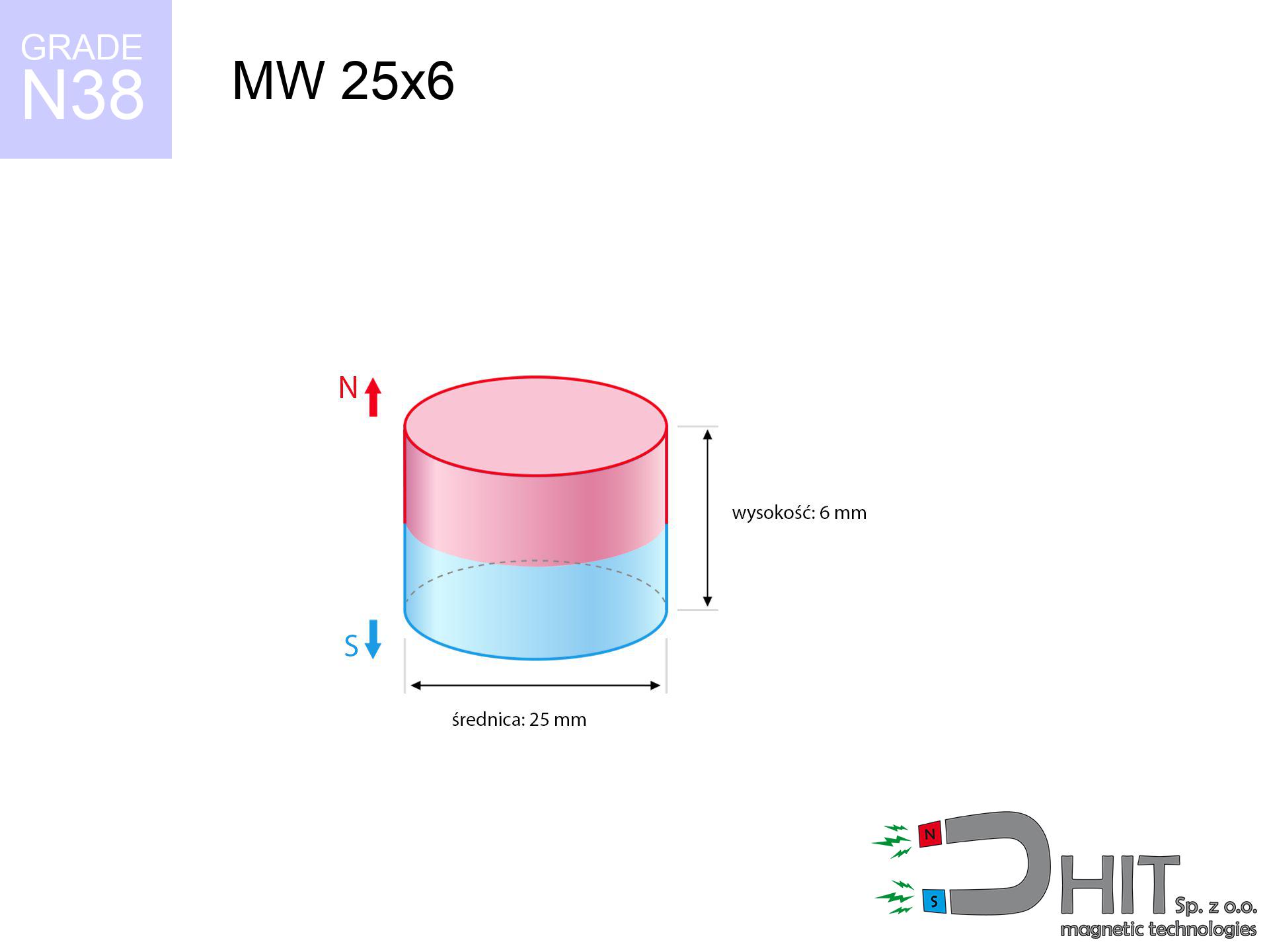
MW 25x6 / N38 - cylindrical magnet
cylindrical magnet
Catalog no 010050
GTIN/EAN: 5906301810490
Diameter Ø
25 mm [±0,1 mm]
Height
6 mm [±0,1 mm]
Weight
22.09 g
Magnetization Direction
↑ axial
Load capacity
10.27 kg / 100.71 N
Magnetic Induction
268.21 mT / 2682 Gs
Coating
[NiCuNi] Nickel
7.40 ZŁ with VAT / pcs + price for transport
6.02 ZŁ net + 23% VAT / pcs
bulk discounts:
Need more?
Give us a call
+48 22 499 98 98
if you prefer let us know by means of
contact form
our website.
Specifications along with shape of a neodymium magnet can be analyzed on our
magnetic calculator.
Order by 14:00 and we’ll ship today!
Technical specification of the product - MW 25x6 / N38 - cylindrical magnet
Specification / characteristics - MW 25x6 / N38 - cylindrical magnet
| properties | values |
|---|---|
| Cat. no. | 010050 |
| GTIN/EAN | 5906301810490 |
| Production/Distribution | Dhit sp. z o.o. |
| Country of origin | Poland / China / Germany |
| Customs code | 85059029 |
| Diameter Ø | 25 mm [±0,1 mm] |
| Height | 6 mm [±0,1 mm] |
| Weight | 22.09 g |
| Magnetization Direction | ↑ axial |
| Load capacity ~ ? | 10.27 kg / 100.71 N |
| Magnetic Induction ~ ? | 268.21 mT / 2682 Gs |
| Coating | [NiCuNi] Nickel |
| Manufacturing Tolerance | ±0.1 mm |
Magnetic properties of material N38
| properties | values | units |
|---|---|---|
| remenance Br [min. - max.] ? | 12.2-12.6 | kGs |
| remenance Br [min. - max.] ? | 1220-1260 | mT |
| coercivity bHc ? | 10.8-11.5 | kOe |
| coercivity bHc ? | 860-915 | kA/m |
| actual internal force iHc | ≥ 12 | kOe |
| actual internal force iHc | ≥ 955 | kA/m |
| energy density [min. - max.] ? | 36-38 | BH max MGOe |
| energy density [min. - max.] ? | 287-303 | BH max KJ/m |
| max. temperature ? | ≤ 80 | °C |
Physical properties of sintered neodymium magnets Nd2Fe14B at 20°C
| properties | values | units |
|---|---|---|
| Vickers hardness | ≥550 | Hv |
| Density | ≥7.4 | g/cm3 |
| Curie Temperature TC | 312 - 380 | °C |
| Curie Temperature TF | 593 - 716 | °F |
| Specific resistance | 150 | μΩ⋅cm |
| Bending strength | 250 | MPa |
| Compressive strength | 1000~1100 | MPa |
| Thermal expansion parallel (∥) to orientation (M) | (3-4) x 10-6 | °C-1 |
| Thermal expansion perpendicular (⊥) to orientation (M) | -(1-3) x 10-6 | °C-1 |
| Young's modulus | 1.7 x 10⁴ | kg/mm² |
Physical modeling of the product - data
These data constitute the direct effect of a physical analysis. Results were calculated on algorithms for the class Nd2Fe14B. Actual parameters may differ. Please consider these calculations as a supplementary guide when designing systems.
Table 1: Static force (pull vs distance) - characteristics
MW 25x6 / N38
| Distance (mm) | Induction (Gauss) / mT | Pull Force (kg/lbs/g/N) | Risk Status |
|---|---|---|---|
| 0 mm |
2682 Gs
268.2 mT
|
10.27 kg / 22.64 lbs
10270.0 g / 100.7 N
|
critical level |
| 1 mm |
2535 Gs
253.5 mT
|
9.18 kg / 20.23 lbs
9177.2 g / 90.0 N
|
warning |
| 2 mm |
2363 Gs
236.3 mT
|
7.97 kg / 17.57 lbs
7971.8 g / 78.2 N
|
warning |
| 3 mm |
2176 Gs
217.6 mT
|
6.76 kg / 14.91 lbs
6761.0 g / 66.3 N
|
warning |
| 5 mm |
1793 Gs
179.3 mT
|
4.59 kg / 10.13 lbs
4592.7 g / 45.1 N
|
warning |
| 10 mm |
1013 Gs
101.3 mT
|
1.46 kg / 3.23 lbs
1464.5 g / 14.4 N
|
low risk |
| 15 mm |
565 Gs
56.5 mT
|
0.46 kg / 1.00 lbs
455.3 g / 4.5 N
|
low risk |
| 20 mm |
330 Gs
33.0 mT
|
0.16 kg / 0.34 lbs
155.7 g / 1.5 N
|
low risk |
| 30 mm |
134 Gs
13.4 mT
|
0.03 kg / 0.06 lbs
25.6 g / 0.3 N
|
low risk |
| 50 mm |
36 Gs
3.6 mT
|
0.00 kg / 0.00 lbs
1.9 g / 0.0 N
|
low risk |
Table 2: Slippage capacity (vertical surface)
MW 25x6 / N38
| Distance (mm) | Friction coefficient | Pull Force (kg/lbs/g/N) |
|---|---|---|
| 0 mm | Stal (~0.2) |
2.05 kg / 4.53 lbs
2054.0 g / 20.1 N
|
| 1 mm | Stal (~0.2) |
1.84 kg / 4.05 lbs
1836.0 g / 18.0 N
|
| 2 mm | Stal (~0.2) |
1.59 kg / 3.51 lbs
1594.0 g / 15.6 N
|
| 3 mm | Stal (~0.2) |
1.35 kg / 2.98 lbs
1352.0 g / 13.3 N
|
| 5 mm | Stal (~0.2) |
0.92 kg / 2.02 lbs
918.0 g / 9.0 N
|
| 10 mm | Stal (~0.2) |
0.29 kg / 0.64 lbs
292.0 g / 2.9 N
|
| 15 mm | Stal (~0.2) |
0.09 kg / 0.20 lbs
92.0 g / 0.9 N
|
| 20 mm | Stal (~0.2) |
0.03 kg / 0.07 lbs
32.0 g / 0.3 N
|
| 30 mm | Stal (~0.2) |
0.01 kg / 0.01 lbs
6.0 g / 0.1 N
|
| 50 mm | Stal (~0.2) |
0.00 kg / 0.00 lbs
0.0 g / 0.0 N
|
Table 3: Wall mounting (sliding) - behavior on slippery surfaces
MW 25x6 / N38
| Surface type | Friction coefficient / % Mocy | Max load (kg/lbs/g/N) |
|---|---|---|
| Raw steel |
µ = 0.3
30% Nominalnej Siły
|
3.08 kg / 6.79 lbs
3081.0 g / 30.2 N
|
| Painted steel (standard) |
µ = 0.2
20% Nominalnej Siły
|
2.05 kg / 4.53 lbs
2054.0 g / 20.1 N
|
| Oily/slippery steel |
µ = 0.1
10% Nominalnej Siły
|
1.03 kg / 2.26 lbs
1027.0 g / 10.1 N
|
| Magnet with anti-slip rubber |
µ = 0.5
50% Nominalnej Siły
|
5.14 kg / 11.32 lbs
5135.0 g / 50.4 N
|
Table 4: Material efficiency (saturation) - power losses
MW 25x6 / N38
| Steel thickness (mm) | % power | Real pull force (kg/lbs/g/N) |
|---|---|---|
| 0.5 mm |
|
0.51 kg / 1.13 lbs
513.5 g / 5.0 N
|
| 1 mm |
|
1.28 kg / 2.83 lbs
1283.8 g / 12.6 N
|
| 2 mm |
|
2.57 kg / 5.66 lbs
2567.5 g / 25.2 N
|
| 3 mm |
|
3.85 kg / 8.49 lbs
3851.3 g / 37.8 N
|
| 5 mm |
|
6.42 kg / 14.15 lbs
6418.7 g / 63.0 N
|
| 10 mm |
|
10.27 kg / 22.64 lbs
10270.0 g / 100.7 N
|
| 11 mm |
|
10.27 kg / 22.64 lbs
10270.0 g / 100.7 N
|
| 12 mm |
|
10.27 kg / 22.64 lbs
10270.0 g / 100.7 N
|
Table 5: Thermal resistance (stability) - power drop
MW 25x6 / N38
| Ambient temp. (°C) | Power loss | Remaining pull (kg/lbs/g/N) | Status |
|---|---|---|---|
| 20 °C | 0.0% |
10.27 kg / 22.64 lbs
10270.0 g / 100.7 N
|
OK |
| 40 °C | -2.2% |
10.04 kg / 22.14 lbs
10044.1 g / 98.5 N
|
OK |
| 60 °C | -4.4% |
9.82 kg / 21.65 lbs
9818.1 g / 96.3 N
|
|
| 80 °C | -6.6% |
9.59 kg / 21.15 lbs
9592.2 g / 94.1 N
|
|
| 100 °C | -28.8% |
7.31 kg / 16.12 lbs
7312.2 g / 71.7 N
|
Table 6: Magnet-Magnet interaction (attraction) - field range
MW 25x6 / N38
| Gap (mm) | Attraction (kg/lbs) (N-S) | Shear Strength (kg/lbs/g/N) | Repulsion (kg/lbs) (N-N) |
|---|---|---|---|
| 0 mm |
21.76 kg / 47.98 lbs
4 291 Gs
|
3.26 kg / 7.20 lbs
3264 g / 32.0 N
|
N/A |
| 1 mm |
20.66 kg / 45.54 lbs
5 225 Gs
|
3.10 kg / 6.83 lbs
3098 g / 30.4 N
|
18.59 kg / 40.98 lbs
~0 Gs
|
| 2 mm |
19.45 kg / 42.87 lbs
5 070 Gs
|
2.92 kg / 6.43 lbs
2917 g / 28.6 N
|
17.50 kg / 38.58 lbs
~0 Gs
|
| 3 mm |
18.18 kg / 40.09 lbs
4 902 Gs
|
2.73 kg / 6.01 lbs
2727 g / 26.8 N
|
16.36 kg / 36.08 lbs
~0 Gs
|
| 5 mm |
15.60 kg / 34.39 lbs
4 541 Gs
|
2.34 kg / 5.16 lbs
2340 g / 23.0 N
|
14.04 kg / 30.95 lbs
~0 Gs
|
| 10 mm |
9.73 kg / 21.46 lbs
3 587 Gs
|
1.46 kg / 3.22 lbs
1460 g / 14.3 N
|
8.76 kg / 19.31 lbs
~0 Gs
|
| 20 mm |
3.10 kg / 6.84 lbs
2 025 Gs
|
0.47 kg / 1.03 lbs
465 g / 4.6 N
|
2.79 kg / 6.16 lbs
~0 Gs
|
| 50 mm |
0.13 kg / 0.28 lbs
409 Gs
|
0.02 kg / 0.04 lbs
19 g / 0.2 N
|
0.11 kg / 0.25 lbs
~0 Gs
|
| 60 mm |
0.05 kg / 0.12 lbs
268 Gs
|
0.01 kg / 0.02 lbs
8 g / 0.1 N
|
0.05 kg / 0.11 lbs
~0 Gs
|
| 70 mm |
0.03 kg / 0.06 lbs
183 Gs
|
0.00 kg / 0.01 lbs
4 g / 0.0 N
|
0.02 kg / 0.05 lbs
~0 Gs
|
| 80 mm |
0.01 kg / 0.03 lbs
131 Gs
|
0.00 kg / 0.00 lbs
2 g / 0.0 N
|
0.01 kg / 0.03 lbs
~0 Gs
|
| 90 mm |
0.01 kg / 0.02 lbs
96 Gs
|
0.00 kg / 0.00 lbs
1 g / 0.0 N
|
0.00 kg / 0.00 lbs
~0 Gs
|
| 100 mm |
0.00 kg / 0.01 lbs
72 Gs
|
0.00 kg / 0.00 lbs
1 g / 0.0 N
|
0.00 kg / 0.00 lbs
~0 Gs
|
Table 7: Protective zones (implants) - warnings
MW 25x6 / N38
| Object / Device | Limit (Gauss) / mT | Safe distance |
|---|---|---|
| Pacemaker | 5 Gs (0.5 mT) | 10.5 cm |
| Hearing aid | 10 Gs (1.0 mT) | 8.0 cm |
| Mechanical watch | 20 Gs (2.0 mT) | 6.5 cm |
| Phone / Smartphone | 40 Gs (4.0 mT) | 5.0 cm |
| Remote | 50 Gs (5.0 mT) | 4.5 cm |
| Payment card | 400 Gs (40.0 mT) | 2.0 cm |
| HDD hard drive | 600 Gs (60.0 mT) | 1.5 cm |
Table 8: Collisions (cracking risk) - warning
MW 25x6 / N38
| Start from (mm) | Speed (km/h) | Energy (J) | Predicted outcome |
|---|---|---|---|
| 10 mm |
23.60 km/h
(6.56 m/s)
|
0.47 J | |
| 30 mm |
37.72 km/h
(10.48 m/s)
|
1.21 J | |
| 50 mm |
48.63 km/h
(13.51 m/s)
|
2.02 J | |
| 100 mm |
68.77 km/h
(19.10 m/s)
|
4.03 J |
Table 9: Surface protection spec
MW 25x6 / N38
| Technical parameter | Value / Description |
|---|---|
| Coating type | [NiCuNi] Nickel |
| Layer structure | Nickel - Copper - Nickel |
| Layer thickness | 10-20 µm |
| Salt spray test (SST) ? | 24 h |
| Recommended environment | Indoors only (dry) |
Table 10: Construction data (Pc)
MW 25x6 / N38
| Parameter | Value | SI Unit / Description |
|---|---|---|
| Magnetic Flux | 14 740 Mx | 147.4 µWb |
| Pc Coefficient | 0.34 | Low (Flat) |
Table 11: Hydrostatics and buoyancy
MW 25x6 / N38
| Environment | Effective steel pull | Effect |
|---|---|---|
| Air (land) | 10.27 kg | Standard |
| Water (riverbed) |
11.76 kg
(+1.49 kg buoyancy gain)
|
+14.5% |
1. Sliding resistance
*Warning: On a vertical wall, the magnet retains just approx. 20-30% of its max power.
2. Steel saturation
*Thin metal sheet (e.g. computer case) drastically limits the holding force.
3. Temperature resistance
*For N38 grade, the critical limit is 80°C.
4. Demagnetization curve and operating point (B-H)
chart generated for the permeance coefficient Pc (Permeance Coefficient) = 0.34
This simulation demonstrates the magnetic stability of the selected magnet under specific geometric conditions. The solid red line represents the demagnetization curve (material potential), while the dashed blue line is the load line based on the magnet's geometry. The Pc (Permeance Coefficient), also known as the load line slope, is a dimensionless value that describes the relationship between the magnet's shape and its magnetic stability. The intersection of these two lines (the black dot) is the operating point — it determines the actual magnetic flux density generated by the magnet in this specific configuration. A higher Pc value means the magnet is more 'slender' (tall relative to its area), resulting in a higher operating point and better resistance to irreversible demagnetization caused by external fields or temperature. A value of 0.42 is relatively low (typical for flat magnets), meaning the operating point is closer to the 'knee' of the curve — caution is advised when operating at temperatures near the maximum limit to avoid strength loss.
Elemental analysis
| iron (Fe) | 64% – 68% |
| neodymium (Nd) | 29% – 32% |
| boron (B) | 1.1% – 1.2% |
| dysprosium (Dy) | 0.5% – 2.0% |
| coating (Ni-Cu-Ni) | < 0.05% |
Sustainability
| recyclability (EoL) | 100% |
| recycled raw materials | ~10% (pre-cons) |
| carbon footprint | low / zredukowany |
| waste code (EWC) | 16 02 16 |
View also proposals

![SM 32x375 [2xM8] / N52 - magnetic separator](https://cdn3.dhit.pl/graphics/products/sm-32x375-2xm8-mif.jpg "SM 32x375 [2xM8] / N52 - magnetic separator")

![SM 25x200 [2xM8] / N42 - magnetic separator](https://cdn3.dhit.pl/graphics/products/sm-25x200-2xm8-dos.jpg "SM 25x200 [2xM8] / N42 - magnetic separator")
Advantages as well as disadvantages of rare earth magnets.
Strengths
- They virtually do not lose strength, because even after ten years the performance loss is only ~1% (based on calculations),
- They do not lose their magnetic properties even under close interference source,
- A magnet with a smooth nickel surface has better aesthetics,
- Neodymium magnets achieve maximum magnetic induction on a small surface, which allows for strong attraction,
- Thanks to resistance to high temperature, they are capable of working (depending on the shape) even at temperatures up to 230°C and higher...
- Thanks to versatility in designing and the ability to modify to client solutions,
- Huge importance in advanced technology sectors – they find application in data components, drive modules, advanced medical instruments, also technologically advanced constructions.
- Thanks to their power density, small magnets offer high operating force, with minimal size,
Disadvantages
- They are fragile upon too strong impacts. To avoid cracks, it is worth securing magnets using a steel holder. Such protection not only protects the magnet but also increases its resistance to damage
- When exposed to high temperature, neodymium magnets suffer a drop in power. Often, when the temperature exceeds 80°C, their power decreases (depending on the size, as well as shape of the magnet). For those who need magnets for extreme conditions, we offer [AH] versions withstanding up to 230°C
- Due to the susceptibility of magnets to corrosion in a humid environment, we suggest using waterproof magnets made of rubber, plastic or other material resistant to moisture, when using outdoors
- Limited ability of creating threads in the magnet and complicated forms - preferred is casing - mounting mechanism.
- Possible danger related to microscopic parts of magnets can be dangerous, if swallowed, which is particularly important in the context of child health protection. It is also worth noting that small elements of these products are able to complicate diagnosis medical when they are in the body.
- High unit price – neodymium magnets cost more than other types of magnets (e.g. ferrite), which hinders application in large quantities
Lifting parameters
Highest magnetic holding force – what affects it?
- on a plate made of structural steel, optimally conducting the magnetic flux
- with a cross-section no less than 10 mm
- with a plane free of scratches
- with direct contact (no paint)
- for force applied at a right angle (in the magnet axis)
- at conditions approx. 20°C
Lifting capacity in real conditions – factors
- Gap between magnet and steel – even a fraction of a millimeter of distance (caused e.g. by varnish or dirt) significantly weakens the pulling force, often by half at just 0.5 mm.
- Angle of force application – maximum parameter is obtained only during pulling at a 90° angle. The force required to slide of the magnet along the surface is typically many times smaller (approx. 1/5 of the lifting capacity).
- Wall thickness – thin material does not allow full use of the magnet. Magnetic flux passes through the material instead of generating force.
- Material type – the best choice is high-permeability steel. Stainless steels may attract less.
- Surface finish – full contact is obtained only on smooth steel. Any scratches and bumps create air cushions, reducing force.
- Thermal factor – hot environment reduces magnetic field. Too high temperature can permanently damage the magnet.
Lifting capacity testing was performed on plates with a smooth surface of optimal thickness, under perpendicular forces, however under parallel forces the holding force is lower. Additionally, even a minimal clearance between the magnet and the plate decreases the load capacity.
Safety rules for work with NdFeB magnets
Hand protection
Pinching hazard: The attraction force is so great that it can cause hematomas, crushing, and even bone fractures. Use thick gloves.
Allergic reactions
It is widely known that nickel (the usual finish) is a potent allergen. For allergy sufferers, refrain from touching magnets with bare hands or opt for coated magnets.
Fire risk
Fire warning: Neodymium dust is highly flammable. Avoid machining magnets in home conditions as this may cause fire.
No play value
These products are not intended for children. Eating several magnets can lead to them pinching intestinal walls, which poses a direct threat to life and necessitates urgent medical intervention.
Thermal limits
Standard neodymium magnets (N-type) lose power when the temperature goes above 80°C. Damage is permanent.
Health Danger
Medical warning: Neodymium magnets can deactivate heart devices and defibrillators. Stay away if you have medical devices.
Safe operation
Use magnets consciously. Their powerful strength can surprise even professionals. Plan your moves and respect their force.
Keep away from computers
Do not bring magnets near a wallet, computer, or screen. The magnetic field can destroy these devices and wipe information from cards.
Magnetic interference
Navigation devices and mobile phones are highly sensitive to magnetism. Direct contact with a powerful NdFeB magnet can permanently damage the internal compass in your phone.
Fragile material
Despite metallic appearance, neodymium is delicate and cannot withstand shocks. Do not hit, as the magnet may crumble into hazardous fragments.
Tabela kosztu i czasu dostawy
Płatność przed wysyłką:

GLS kurier
Przesyłka będzie u Ciebie za 2-3 dni
14.99 ZŁ

InPost Paczkomaty 24/7
Przesyłka będzie u Ciebie za 1-2 dni
12.30 ZŁ
Płatność przy odbiorze (pobranie):
GLS kurier
Przesyłka będzie u Ciebie za 1-2 dni
23.00 ZŁ
Rate the product
Your rating