
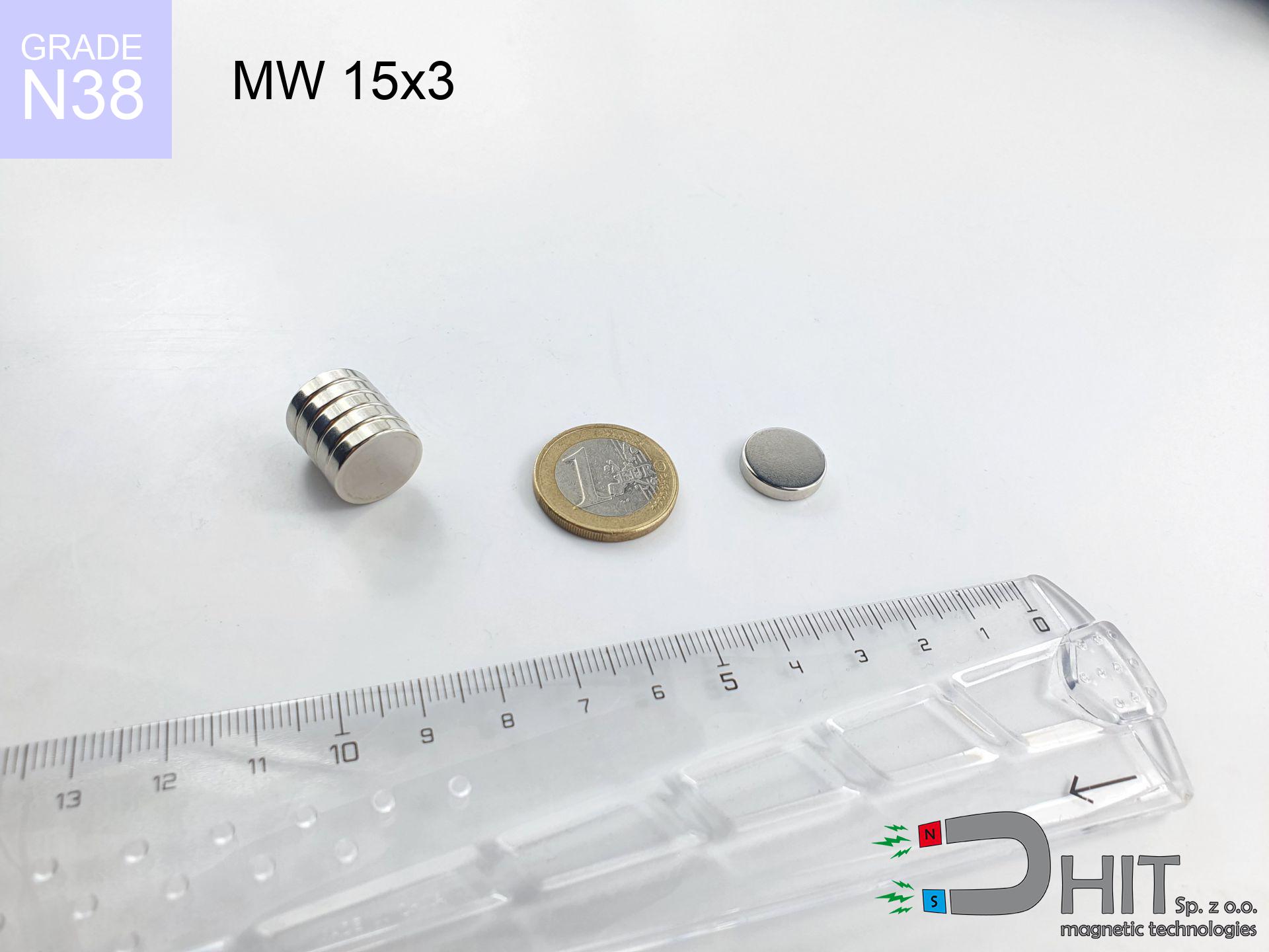
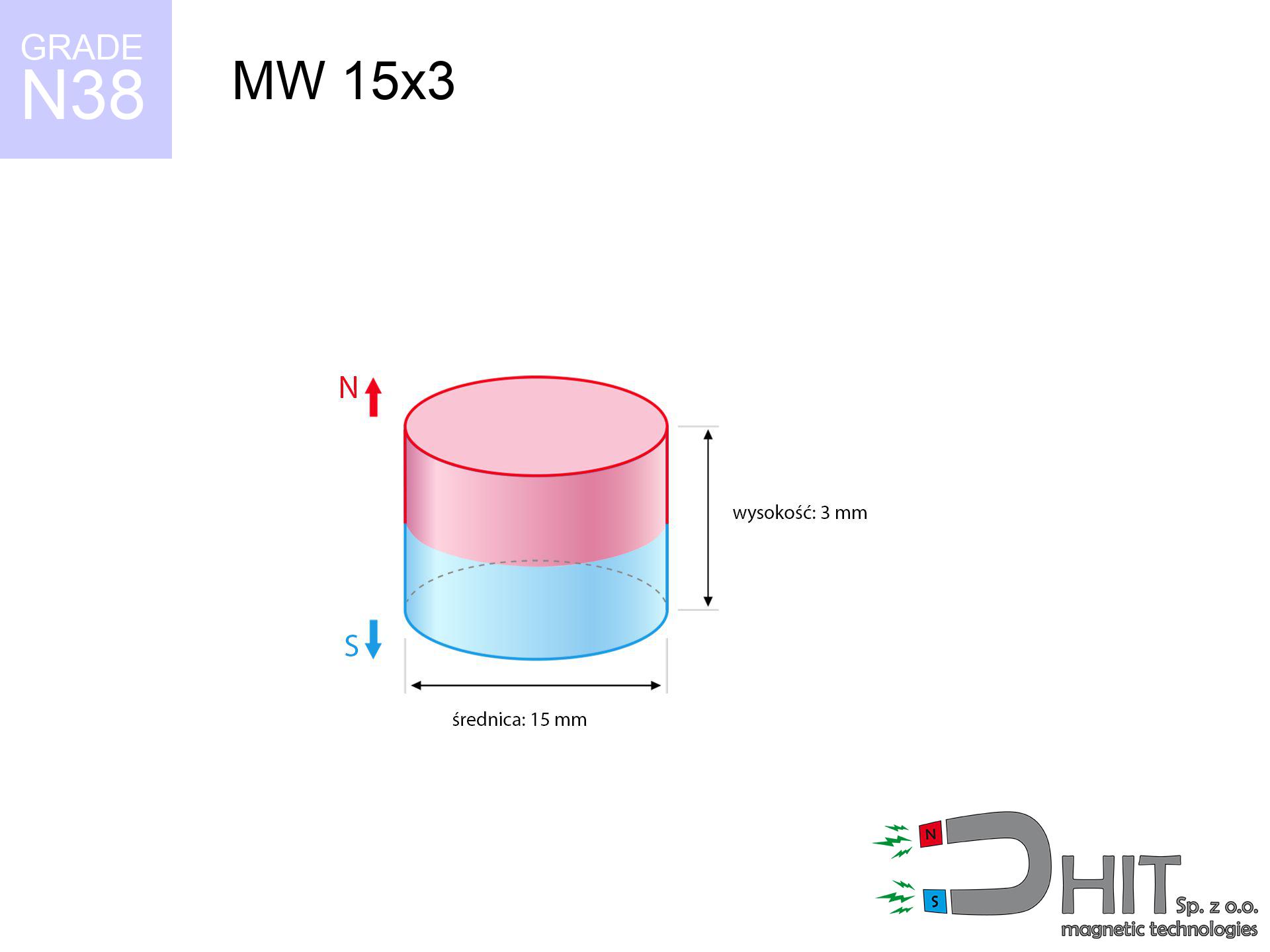
MW 15x3 / N38 - cylindrical magnet
cylindrical magnet
Catalog no 010029
GTIN/EAN: 5906301810285
Diameter Ø
15 mm [±0,1 mm]
Height
3 mm [±0,1 mm]
Weight
3.98 g
Magnetization Direction
↑ axial
Load capacity
2.87 kg / 28.14 N
Magnetic Induction
230.16 mT / 2302 Gs
Coating
[NiCuNi] Nickel
1.624 ZŁ with VAT / pcs + price for transport
1.320 ZŁ net + 23% VAT / pcs
bulk discounts:
Need more?
Pick up the phone and ask
+48 22 499 98 98
if you prefer get in touch using
request form
our website.
Parameters along with appearance of magnets can be analyzed on our
our magnetic calculator.
Orders submitted before 14:00 will be dispatched today!
Physical properties - MW 15x3 / N38 - cylindrical magnet
Specification / characteristics - MW 15x3 / N38 - cylindrical magnet
| properties | values |
|---|---|
| Cat. no. | 010029 |
| GTIN/EAN | 5906301810285 |
| Production/Distribution | Dhit sp. z o.o. |
| Country of origin | Poland / China / Germany |
| Customs code | 85059029 |
| Diameter Ø | 15 mm [±0,1 mm] |
| Height | 3 mm [±0,1 mm] |
| Weight | 3.98 g |
| Magnetization Direction | ↑ axial |
| Load capacity ~ ? | 2.87 kg / 28.14 N |
| Magnetic Induction ~ ? | 230.16 mT / 2302 Gs |
| Coating | [NiCuNi] Nickel |
| Manufacturing Tolerance | ±0.1 mm |
Magnetic properties of material N38
| properties | values | units |
|---|---|---|
| remenance Br [min. - max.] ? | 12.2-12.6 | kGs |
| remenance Br [min. - max.] ? | 1220-1260 | mT |
| coercivity bHc ? | 10.8-11.5 | kOe |
| coercivity bHc ? | 860-915 | kA/m |
| actual internal force iHc | ≥ 12 | kOe |
| actual internal force iHc | ≥ 955 | kA/m |
| energy density [min. - max.] ? | 36-38 | BH max MGOe |
| energy density [min. - max.] ? | 287-303 | BH max KJ/m |
| max. temperature ? | ≤ 80 | °C |
Physical properties of sintered neodymium magnets Nd2Fe14B at 20°C
| properties | values | units |
|---|---|---|
| Vickers hardness | ≥550 | Hv |
| Density | ≥7.4 | g/cm3 |
| Curie Temperature TC | 312 - 380 | °C |
| Curie Temperature TF | 593 - 716 | °F |
| Specific resistance | 150 | μΩ⋅cm |
| Bending strength | 250 | MPa |
| Compressive strength | 1000~1100 | MPa |
| Thermal expansion parallel (∥) to orientation (M) | (3-4) x 10-6 | °C-1 |
| Thermal expansion perpendicular (⊥) to orientation (M) | -(1-3) x 10-6 | °C-1 |
| Young's modulus | 1.7 x 10⁴ | kg/mm² |
Engineering simulation of the magnet - technical parameters
The following information represent the direct effect of a mathematical simulation. Values were calculated on models for the class Nd2Fe14B. Real-world performance may deviate from the simulation results. Please consider these data as a supplementary guide for designers.
Table 1: Static force (pull vs gap) - characteristics
MW 15x3 / N38
| Distance (mm) | Induction (Gauss) / mT | Pull Force (kg/lbs/g/N) | Risk Status |
|---|---|---|---|
| 0 mm |
2301 Gs
230.1 mT
|
2.87 kg / 6.33 lbs
2870.0 g / 28.2 N
|
strong |
| 1 mm |
2098 Gs
209.8 mT
|
2.39 kg / 5.26 lbs
2386.5 g / 23.4 N
|
strong |
| 2 mm |
1842 Gs
184.2 mT
|
1.84 kg / 4.05 lbs
1838.5 g / 18.0 N
|
safe |
| 3 mm |
1570 Gs
157.0 mT
|
1.34 kg / 2.95 lbs
1337.0 g / 13.1 N
|
safe |
| 5 mm |
1084 Gs
108.4 mT
|
0.64 kg / 1.40 lbs
637.0 g / 6.2 N
|
safe |
| 10 mm |
410 Gs
41.0 mT
|
0.09 kg / 0.20 lbs
91.3 g / 0.9 N
|
safe |
| 15 mm |
178 Gs
17.8 mT
|
0.02 kg / 0.04 lbs
17.1 g / 0.2 N
|
safe |
| 20 mm |
89 Gs
8.9 mT
|
0.00 kg / 0.01 lbs
4.3 g / 0.0 N
|
safe |
| 30 mm |
31 Gs
3.1 mT
|
0.00 kg / 0.00 lbs
0.5 g / 0.0 N
|
safe |
| 50 mm |
7 Gs
0.7 mT
|
0.00 kg / 0.00 lbs
0.0 g / 0.0 N
|
safe |
Table 2: Shear capacity (wall)
MW 15x3 / N38
| Distance (mm) | Friction coefficient | Pull Force (kg/lbs/g/N) |
|---|---|---|
| 0 mm | Stal (~0.2) |
0.57 kg / 1.27 lbs
574.0 g / 5.6 N
|
| 1 mm | Stal (~0.2) |
0.48 kg / 1.05 lbs
478.0 g / 4.7 N
|
| 2 mm | Stal (~0.2) |
0.37 kg / 0.81 lbs
368.0 g / 3.6 N
|
| 3 mm | Stal (~0.2) |
0.27 kg / 0.59 lbs
268.0 g / 2.6 N
|
| 5 mm | Stal (~0.2) |
0.13 kg / 0.28 lbs
128.0 g / 1.3 N
|
| 10 mm | Stal (~0.2) |
0.02 kg / 0.04 lbs
18.0 g / 0.2 N
|
| 15 mm | Stal (~0.2) |
0.00 kg / 0.01 lbs
4.0 g / 0.0 N
|
| 20 mm | Stal (~0.2) |
0.00 kg / 0.00 lbs
0.0 g / 0.0 N
|
| 30 mm | Stal (~0.2) |
0.00 kg / 0.00 lbs
0.0 g / 0.0 N
|
| 50 mm | Stal (~0.2) |
0.00 kg / 0.00 lbs
0.0 g / 0.0 N
|
Table 3: Vertical assembly (sliding) - behavior on slippery surfaces
MW 15x3 / N38
| Surface type | Friction coefficient / % Mocy | Max load (kg/lbs/g/N) |
|---|---|---|
| Raw steel |
µ = 0.3
30% Nominalnej Siły
|
0.86 kg / 1.90 lbs
861.0 g / 8.4 N
|
| Painted steel (standard) |
µ = 0.2
20% Nominalnej Siły
|
0.57 kg / 1.27 lbs
574.0 g / 5.6 N
|
| Oily/slippery steel |
µ = 0.1
10% Nominalnej Siły
|
0.29 kg / 0.63 lbs
287.0 g / 2.8 N
|
| Magnet with anti-slip rubber |
µ = 0.5
50% Nominalnej Siły
|
1.44 kg / 3.16 lbs
1435.0 g / 14.1 N
|
Table 4: Material efficiency (substrate influence) - power losses
MW 15x3 / N38
| Steel thickness (mm) | % power | Real pull force (kg/lbs/g/N) |
|---|---|---|
| 0.5 mm |
|
0.29 kg / 0.63 lbs
287.0 g / 2.8 N
|
| 1 mm |
|
0.72 kg / 1.58 lbs
717.5 g / 7.0 N
|
| 2 mm |
|
1.44 kg / 3.16 lbs
1435.0 g / 14.1 N
|
| 3 mm |
|
2.15 kg / 4.75 lbs
2152.5 g / 21.1 N
|
| 5 mm |
|
2.87 kg / 6.33 lbs
2870.0 g / 28.2 N
|
| 10 mm |
|
2.87 kg / 6.33 lbs
2870.0 g / 28.2 N
|
| 11 mm |
|
2.87 kg / 6.33 lbs
2870.0 g / 28.2 N
|
| 12 mm |
|
2.87 kg / 6.33 lbs
2870.0 g / 28.2 N
|
Table 5: Thermal resistance (stability) - resistance threshold
MW 15x3 / N38
| Ambient temp. (°C) | Power loss | Remaining pull (kg/lbs/g/N) | Status |
|---|---|---|---|
| 20 °C | 0.0% |
2.87 kg / 6.33 lbs
2870.0 g / 28.2 N
|
OK |
| 40 °C | -2.2% |
2.81 kg / 6.19 lbs
2806.9 g / 27.5 N
|
OK |
| 60 °C | -4.4% |
2.74 kg / 6.05 lbs
2743.7 g / 26.9 N
|
|
| 80 °C | -6.6% |
2.68 kg / 5.91 lbs
2680.6 g / 26.3 N
|
|
| 100 °C | -28.8% |
2.04 kg / 4.51 lbs
2043.4 g / 20.0 N
|
Table 6: Two magnets (attraction) - forces in the system
MW 15x3 / N38
| Gap (mm) | Attraction (kg/lbs) (N-S) | Shear Force (kg/lbs/g/N) | Repulsion (kg/lbs) (N-N) |
|---|---|---|---|
| 0 mm |
5.77 kg / 12.72 lbs
3 869 Gs
|
0.87 kg / 1.91 lbs
865 g / 8.5 N
|
N/A |
| 1 mm |
5.32 kg / 11.73 lbs
4 419 Gs
|
0.80 kg / 1.76 lbs
798 g / 7.8 N
|
4.79 kg / 10.55 lbs
~0 Gs
|
| 2 mm |
4.80 kg / 10.57 lbs
4 196 Gs
|
0.72 kg / 1.59 lbs
719 g / 7.1 N
|
4.32 kg / 9.52 lbs
~0 Gs
|
| 3 mm |
4.25 kg / 9.36 lbs
3 948 Gs
|
0.64 kg / 1.40 lbs
637 g / 6.2 N
|
3.82 kg / 8.42 lbs
~0 Gs
|
| 5 mm |
3.17 kg / 6.99 lbs
3 412 Gs
|
0.48 kg / 1.05 lbs
476 g / 4.7 N
|
2.85 kg / 6.29 lbs
~0 Gs
|
| 10 mm |
1.28 kg / 2.82 lbs
2 168 Gs
|
0.19 kg / 0.42 lbs
192 g / 1.9 N
|
1.15 kg / 2.54 lbs
~0 Gs
|
| 20 mm |
0.18 kg / 0.40 lbs
821 Gs
|
0.03 kg / 0.06 lbs
28 g / 0.3 N
|
0.17 kg / 0.36 lbs
~0 Gs
|
| 50 mm |
0.00 kg / 0.01 lbs
101 Gs
|
0.00 kg / 0.00 lbs
0 g / 0.0 N
|
0.00 kg / 0.00 lbs
~0 Gs
|
| 60 mm |
0.00 kg / 0.00 lbs
62 Gs
|
0.00 kg / 0.00 lbs
0 g / 0.0 N
|
0.00 kg / 0.00 lbs
~0 Gs
|
| 70 mm |
0.00 kg / 0.00 lbs
41 Gs
|
0.00 kg / 0.00 lbs
0 g / 0.0 N
|
0.00 kg / 0.00 lbs
~0 Gs
|
| 80 mm |
0.00 kg / 0.00 lbs
28 Gs
|
0.00 kg / 0.00 lbs
0 g / 0.0 N
|
0.00 kg / 0.00 lbs
~0 Gs
|
| 90 mm |
0.00 kg / 0.00 lbs
20 Gs
|
0.00 kg / 0.00 lbs
0 g / 0.0 N
|
0.00 kg / 0.00 lbs
~0 Gs
|
| 100 mm |
0.00 kg / 0.00 lbs
15 Gs
|
0.00 kg / 0.00 lbs
0 g / 0.0 N
|
0.00 kg / 0.00 lbs
~0 Gs
|
Table 7: Safety (HSE) (implants) - warnings
MW 15x3 / N38
| Object / Device | Limit (Gauss) / mT | Safe distance |
|---|---|---|
| Pacemaker | 5 Gs (0.5 mT) | 6.0 cm |
| Hearing aid | 10 Gs (1.0 mT) | 5.0 cm |
| Mechanical watch | 20 Gs (2.0 mT) | 4.0 cm |
| Mobile device | 40 Gs (4.0 mT) | 3.0 cm |
| Remote | 50 Gs (5.0 mT) | 3.0 cm |
| Payment card | 400 Gs (40.0 mT) | 1.5 cm |
| HDD hard drive | 600 Gs (60.0 mT) | 1.0 cm |
Table 8: Impact energy (cracking risk) - warning
MW 15x3 / N38
| Start from (mm) | Speed (km/h) | Energy (J) | Predicted outcome |
|---|---|---|---|
| 10 mm |
27.62 km/h
(7.67 m/s)
|
0.12 J | |
| 30 mm |
46.91 km/h
(13.03 m/s)
|
0.34 J | |
| 50 mm |
60.56 km/h
(16.82 m/s)
|
0.56 J | |
| 100 mm |
85.64 km/h
(23.79 m/s)
|
1.13 J |
Table 9: Anti-corrosion coating durability
MW 15x3 / N38
| Technical parameter | Value / Description |
|---|---|
| Coating type | [NiCuNi] Nickel |
| Layer structure | Nickel - Copper - Nickel |
| Layer thickness | 10-20 µm |
| Salt spray test (SST) ? | 24 h |
| Recommended environment | Indoors only (dry) |
Table 10: Construction data (Pc)
MW 15x3 / N38
| Parameter | Value | SI Unit / Description |
|---|---|---|
| Magnetic Flux | 4 718 Mx | 47.2 µWb |
| Pc Coefficient | 0.29 | Low (Flat) |
Table 11: Submerged application
MW 15x3 / N38
| Environment | Effective steel pull | Effect |
|---|---|---|
| Air (land) | 2.87 kg | Standard |
| Water (riverbed) |
3.29 kg
(+0.42 kg buoyancy gain)
|
+14.5% |
1. Wall mount (shear)
*Note: On a vertical wall, the magnet holds merely ~20% of its nominal pull.
2. Steel thickness impact
*Thin metal sheet (e.g. 0.5mm PC case) significantly reduces the holding force.
3. Temperature resistance
*For standard magnets, the max working temp is 80°C.
4. Demagnetization curve and operating point (B-H)
chart generated for the permeance coefficient Pc (Permeance Coefficient) = 0.29
This simulation demonstrates the magnetic stability of the selected magnet under specific geometric conditions. The solid red line represents the demagnetization curve (material potential), while the dashed blue line is the load line based on the magnet's geometry. The Pc (Permeance Coefficient), also known as the load line slope, is a dimensionless value that describes the relationship between the magnet's shape and its magnetic stability. The intersection of these two lines (the black dot) is the operating point — it determines the actual magnetic flux density generated by the magnet in this specific configuration. A higher Pc value means the magnet is more 'slender' (tall relative to its area), resulting in a higher operating point and better resistance to irreversible demagnetization caused by external fields or temperature. A value of 0.42 is relatively low (typical for flat magnets), meaning the operating point is closer to the 'knee' of the curve — caution is advised when operating at temperatures near the maximum limit to avoid strength loss.
Material specification
| iron (Fe) | 64% – 68% |
| neodymium (Nd) | 29% – 32% |
| boron (B) | 1.1% – 1.2% |
| dysprosium (Dy) | 0.5% – 2.0% |
| coating (Ni-Cu-Ni) | < 0.05% |
Ecology and recycling (GPSR)
| recyclability (EoL) | 100% |
| recycled raw materials | ~10% (pre-cons) |
| carbon footprint | low / zredukowany |
| waste code (EWC) | 16 02 16 |
Check out more offers


Pros as well as cons of Nd2Fe14B magnets.
Strengths
- They do not lose power, even after approximately ten years – the decrease in lifting capacity is only ~1% (according to tests),
- They show high resistance to demagnetization induced by external disturbances,
- A magnet with a metallic silver surface is more attractive,
- Neodymium magnets create maximum magnetic induction on a small surface, which increases force concentration,
- Due to their durability and thermal resistance, neodymium magnets can operate (depending on the shape) even at high temperatures reaching 230°C or more...
- Thanks to flexibility in constructing and the ability to modify to unusual requirements,
- Significant place in modern industrial fields – they are utilized in magnetic memories, electric drive systems, advanced medical instruments, and modern systems.
- Compactness – despite small sizes they generate large force, making them ideal for precision applications
Cons
- They are prone to damage upon heavy impacts. To avoid cracks, it is worth securing magnets in special housings. Such protection not only protects the magnet but also increases its resistance to damage
- NdFeB magnets lose force when exposed to high temperatures. After reaching 80°C, many of them experience permanent weakening of strength (a factor is the shape as well as dimensions of the magnet). We offer magnets specially adapted to work at temperatures up to 230°C marked [AH], which are extremely resistant to heat
- Due to the susceptibility of magnets to corrosion in a humid environment, we recommend using waterproof magnets made of rubber, plastic or other material resistant to moisture, in case of application outdoors
- Limited possibility of creating nuts in the magnet and complicated forms - recommended is a housing - magnetic holder.
- Possible danger to health – tiny shards of magnets can be dangerous, if swallowed, which becomes key in the context of child safety. Furthermore, tiny parts of these products are able to complicate diagnosis medical after entering the body.
- With budget limitations the cost of neodymium magnets is economically unviable,
Holding force characteristics
Breakaway strength of the magnet in ideal conditions – what contributes to it?
- on a block made of structural steel, effectively closing the magnetic flux
- possessing a massiveness of minimum 10 mm to ensure full flux closure
- with an polished touching surface
- with direct contact (without paint)
- during detachment in a direction perpendicular to the mounting surface
- in stable room temperature
Determinants of practical lifting force of a magnet
- Distance – existence of foreign body (rust, dirt, gap) acts as an insulator, which lowers power rapidly (even by 50% at 0.5 mm).
- Angle of force application – maximum parameter is reached only during pulling at a 90° angle. The force required to slide of the magnet along the plate is typically several times lower (approx. 1/5 of the lifting capacity).
- Steel thickness – too thin sheet causes magnetic saturation, causing part of the flux to be lost to the other side.
- Metal type – different alloys reacts the same. High carbon content weaken the attraction effect.
- Smoothness – full contact is possible only on smooth steel. Rough texture reduce the real contact area, weakening the magnet.
- Heat – NdFeB sinters have a sensitivity to temperature. When it is hot they are weaker, and at low temperatures they can be stronger (up to a certain limit).
Holding force was measured on the plate surface of 20 mm thickness, when a perpendicular force was applied, in contrast under parallel forces the lifting capacity is smaller. Moreover, even a minimal clearance between the magnet’s surface and the plate lowers the lifting capacity.
Warnings
Skin irritation risks
Warning for allergy sufferers: The nickel-copper-nickel coating contains nickel. If redness appears, cease handling magnets and wear gloves.
Pacemakers
Medical warning: Strong magnets can deactivate heart devices and defibrillators. Stay away if you have medical devices.
Demagnetization risk
Watch the temperature. Exposing the magnet to high heat will permanently weaken its properties and strength.
Pinching danger
Large magnets can crush fingers in a fraction of a second. Do not place your hand betwixt two attracting surfaces.
Protective goggles
Despite the nickel coating, neodymium is delicate and not impact-resistant. Avoid impacts, as the magnet may crumble into sharp, dangerous pieces.
Product not for children
Absolutely store magnets away from children. Risk of swallowing is high, and the effects of magnets clamping inside the body are life-threatening.
Do not drill into magnets
Fire hazard: Rare earth powder is explosive. Do not process magnets in home conditions as this may cause fire.
Immense force
Before starting, check safety instructions. Uncontrolled attraction can destroy the magnet or injure your hand. Be predictive.
Magnetic interference
A strong magnetic field negatively affects the functioning of compasses in smartphones and navigation systems. Keep magnets near a smartphone to prevent damaging the sensors.
Electronic devices
Powerful magnetic fields can destroy records on payment cards, hard drives, and storage devices. Keep a distance of at least 10 cm.
Tabela kosztu i czasu dostawy
Płatność przed wysyłką:

GLS kurier
Przesyłka będzie u Ciebie za 2-3 dni
14.99 ZŁ

InPost Paczkomaty 24/7
Przesyłka będzie u Ciebie za 1-2 dni
12.30 ZŁ
Płatność przy odbiorze (pobranie):
GLS kurier
Przesyłka będzie u Ciebie za 1-2 dni
23.00 ZŁ
Rate the product
Your rating