

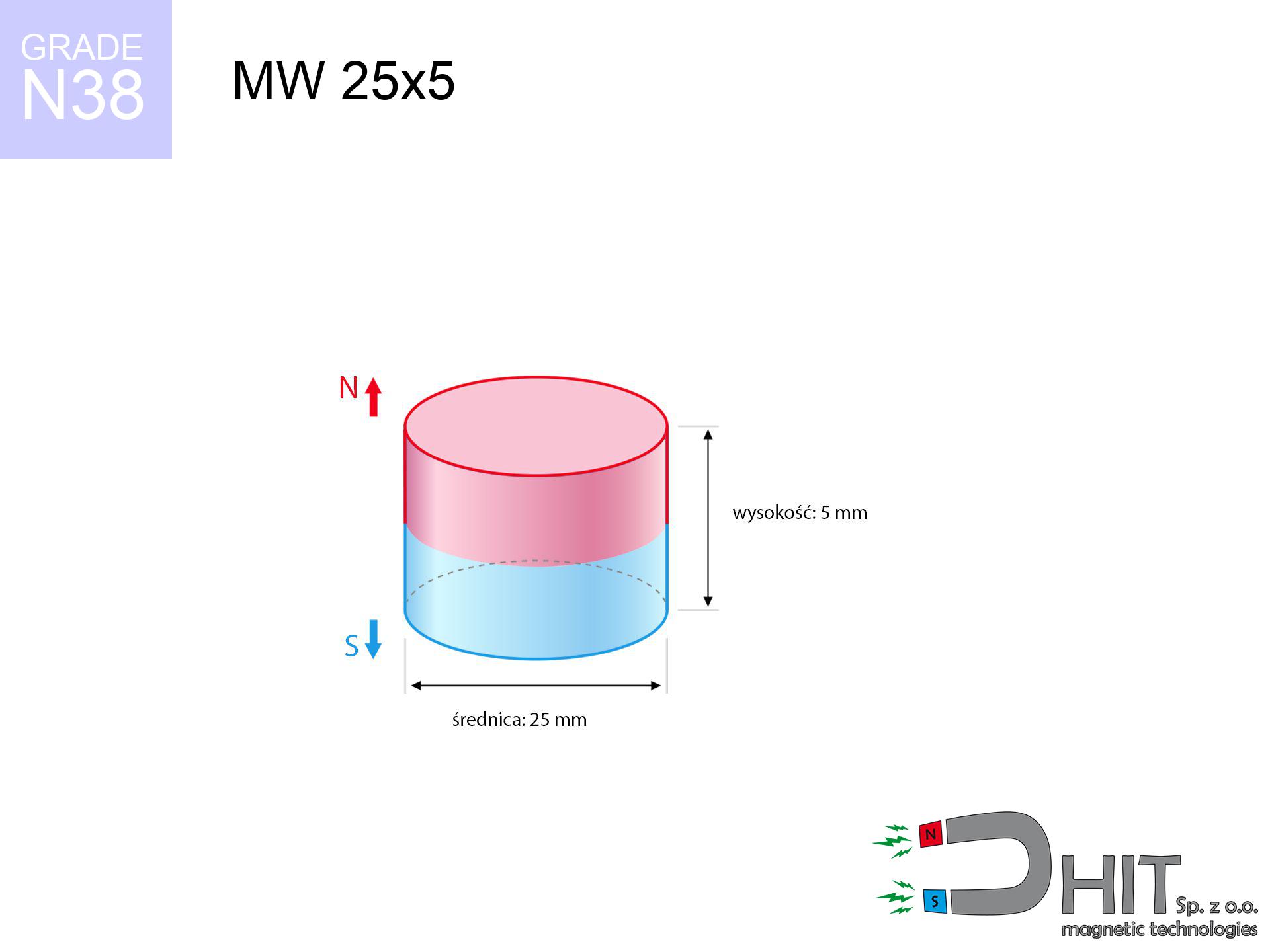
MW 25x5 / N38 - cylindrical magnet
cylindrical magnet
Catalog no 010049
GTIN/EAN: 5906301810483
Diameter Ø
25 mm [±0,1 mm]
Height
5 mm [±0,1 mm]
Weight
18.41 g
Magnetization Direction
↑ axial
Load capacity
7.98 kg / 78.25 N
Magnetic Induction
230.20 mT / 2302 Gs
Coating
[NiCuNi] Nickel
8.39 ZŁ with VAT / pcs + price for transport
6.82 ZŁ net + 23% VAT / pcs
bulk discounts:
Need more?
Call us
+48 22 499 98 98
or get in touch using
inquiry form
our website.
Specifications along with appearance of neodymium magnets can be checked using our
magnetic mass calculator.
Order by 14:00 and we’ll ship today!
Technical of the product - MW 25x5 / N38 - cylindrical magnet
Specification / characteristics - MW 25x5 / N38 - cylindrical magnet
| properties | values |
|---|---|
| Cat. no. | 010049 |
| GTIN/EAN | 5906301810483 |
| Production/Distribution | Dhit sp. z o.o. |
| Country of origin | Poland / China / Germany |
| Customs code | 85059029 |
| Diameter Ø | 25 mm [±0,1 mm] |
| Height | 5 mm [±0,1 mm] |
| Weight | 18.41 g |
| Magnetization Direction | ↑ axial |
| Load capacity ~ ? | 7.98 kg / 78.25 N |
| Magnetic Induction ~ ? | 230.20 mT / 2302 Gs |
| Coating | [NiCuNi] Nickel |
| Manufacturing Tolerance | ±0.1 mm |
Magnetic properties of material N38
| properties | values | units |
|---|---|---|
| remenance Br [min. - max.] ? | 12.2-12.6 | kGs |
| remenance Br [min. - max.] ? | 1220-1260 | mT |
| coercivity bHc ? | 10.8-11.5 | kOe |
| coercivity bHc ? | 860-915 | kA/m |
| actual internal force iHc | ≥ 12 | kOe |
| actual internal force iHc | ≥ 955 | kA/m |
| energy density [min. - max.] ? | 36-38 | BH max MGOe |
| energy density [min. - max.] ? | 287-303 | BH max KJ/m |
| max. temperature ? | ≤ 80 | °C |
Physical properties of sintered neodymium magnets Nd2Fe14B at 20°C
| properties | values | units |
|---|---|---|
| Vickers hardness | ≥550 | Hv |
| Density | ≥7.4 | g/cm3 |
| Curie Temperature TC | 312 - 380 | °C |
| Curie Temperature TF | 593 - 716 | °F |
| Specific resistance | 150 | μΩ⋅cm |
| Bending strength | 250 | MPa |
| Compressive strength | 1000~1100 | MPa |
| Thermal expansion parallel (∥) to orientation (M) | (3-4) x 10-6 | °C-1 |
| Thermal expansion perpendicular (⊥) to orientation (M) | -(1-3) x 10-6 | °C-1 |
| Young's modulus | 1.7 x 10⁴ | kg/mm² |
Engineering simulation of the assembly - technical parameters
These information constitute the direct effect of a mathematical calculation. Values rely on models for the class Nd2Fe14B. Actual parameters may differ from theoretical values. Please consider these data as a supplementary guide during assembly planning.
Table 1: Static force (pull vs distance) - interaction chart
MW 25x5 / N38
| Distance (mm) | Induction (Gauss) / mT | Pull Force (kg/lbs/g/N) | Risk Status |
|---|---|---|---|
| 0 mm |
2302 Gs
230.2 mT
|
7.98 kg / 17.59 lbs
7980.0 g / 78.3 N
|
strong |
| 1 mm |
2189 Gs
218.9 mT
|
7.21 kg / 15.91 lbs
7214.9 g / 70.8 N
|
strong |
| 2 mm |
2050 Gs
205.0 mT
|
6.33 kg / 13.95 lbs
6329.3 g / 62.1 N
|
strong |
| 3 mm |
1895 Gs
189.5 mT
|
5.41 kg / 11.93 lbs
5410.7 g / 53.1 N
|
strong |
| 5 mm |
1570 Gs
157.0 mT
|
3.72 kg / 8.19 lbs
3715.4 g / 36.4 N
|
strong |
| 10 mm |
890 Gs
89.0 mT
|
1.19 kg / 2.63 lbs
1192.8 g / 11.7 N
|
weak grip |
| 15 mm |
495 Gs
49.5 mT
|
0.37 kg / 0.81 lbs
368.5 g / 3.6 N
|
weak grip |
| 20 mm |
288 Gs
28.8 mT
|
0.12 kg / 0.28 lbs
124.8 g / 1.2 N
|
weak grip |
| 30 mm |
116 Gs
11.6 mT
|
0.02 kg / 0.04 lbs
20.2 g / 0.2 N
|
weak grip |
| 50 mm |
31 Gs
3.1 mT
|
0.00 kg / 0.00 lbs
1.4 g / 0.0 N
|
weak grip |
Table 2: Vertical capacity (vertical surface)
MW 25x5 / N38
| Distance (mm) | Friction coefficient | Pull Force (kg/lbs/g/N) |
|---|---|---|
| 0 mm | Stal (~0.2) |
1.60 kg / 3.52 lbs
1596.0 g / 15.7 N
|
| 1 mm | Stal (~0.2) |
1.44 kg / 3.18 lbs
1442.0 g / 14.1 N
|
| 2 mm | Stal (~0.2) |
1.27 kg / 2.79 lbs
1266.0 g / 12.4 N
|
| 3 mm | Stal (~0.2) |
1.08 kg / 2.39 lbs
1082.0 g / 10.6 N
|
| 5 mm | Stal (~0.2) |
0.74 kg / 1.64 lbs
744.0 g / 7.3 N
|
| 10 mm | Stal (~0.2) |
0.24 kg / 0.52 lbs
238.0 g / 2.3 N
|
| 15 mm | Stal (~0.2) |
0.07 kg / 0.16 lbs
74.0 g / 0.7 N
|
| 20 mm | Stal (~0.2) |
0.02 kg / 0.05 lbs
24.0 g / 0.2 N
|
| 30 mm | Stal (~0.2) |
0.00 kg / 0.01 lbs
4.0 g / 0.0 N
|
| 50 mm | Stal (~0.2) |
0.00 kg / 0.00 lbs
0.0 g / 0.0 N
|
Table 3: Vertical assembly (shearing) - behavior on slippery surfaces
MW 25x5 / N38
| Surface type | Friction coefficient / % Mocy | Max load (kg/lbs/g/N) |
|---|---|---|
| Raw steel |
µ = 0.3
30% Nominalnej Siły
|
2.39 kg / 5.28 lbs
2394.0 g / 23.5 N
|
| Painted steel (standard) |
µ = 0.2
20% Nominalnej Siły
|
1.60 kg / 3.52 lbs
1596.0 g / 15.7 N
|
| Oily/slippery steel |
µ = 0.1
10% Nominalnej Siły
|
0.80 kg / 1.76 lbs
798.0 g / 7.8 N
|
| Magnet with anti-slip rubber |
µ = 0.5
50% Nominalnej Siły
|
3.99 kg / 8.80 lbs
3990.0 g / 39.1 N
|
Table 4: Steel thickness (substrate influence) - sheet metal selection
MW 25x5 / N38
| Steel thickness (mm) | % power | Real pull force (kg/lbs/g/N) |
|---|---|---|
| 0.5 mm |
|
0.80 kg / 1.76 lbs
798.0 g / 7.8 N
|
| 1 mm |
|
2.00 kg / 4.40 lbs
1995.0 g / 19.6 N
|
| 2 mm |
|
3.99 kg / 8.80 lbs
3990.0 g / 39.1 N
|
| 3 mm |
|
5.99 kg / 13.19 lbs
5985.0 g / 58.7 N
|
| 5 mm |
|
7.98 kg / 17.59 lbs
7980.0 g / 78.3 N
|
| 10 mm |
|
7.98 kg / 17.59 lbs
7980.0 g / 78.3 N
|
| 11 mm |
|
7.98 kg / 17.59 lbs
7980.0 g / 78.3 N
|
| 12 mm |
|
7.98 kg / 17.59 lbs
7980.0 g / 78.3 N
|
Table 5: Thermal stability (material behavior) - thermal limit
MW 25x5 / N38
| Ambient temp. (°C) | Power loss | Remaining pull (kg/lbs/g/N) | Status |
|---|---|---|---|
| 20 °C | 0.0% |
7.98 kg / 17.59 lbs
7980.0 g / 78.3 N
|
OK |
| 40 °C | -2.2% |
7.80 kg / 17.21 lbs
7804.4 g / 76.6 N
|
OK |
| 60 °C | -4.4% |
7.63 kg / 16.82 lbs
7628.9 g / 74.8 N
|
|
| 80 °C | -6.6% |
7.45 kg / 16.43 lbs
7453.3 g / 73.1 N
|
|
| 100 °C | -28.8% |
5.68 kg / 12.53 lbs
5681.8 g / 55.7 N
|
Table 6: Two magnets (repulsion) - field collision
MW 25x5 / N38
| Gap (mm) | Attraction (kg/lbs) (N-S) | Lateral Force (kg/lbs/g/N) | Repulsion (kg/lbs) (N-N) |
|---|---|---|---|
| 0 mm |
16.03 kg / 35.34 lbs
3 871 Gs
|
2.40 kg / 5.30 lbs
2405 g / 23.6 N
|
N/A |
| 1 mm |
15.31 kg / 33.75 lbs
4 498 Gs
|
2.30 kg / 5.06 lbs
2296 g / 22.5 N
|
13.78 kg / 30.38 lbs
~0 Gs
|
| 2 mm |
14.49 kg / 31.95 lbs
4 377 Gs
|
2.17 kg / 4.79 lbs
2174 g / 21.3 N
|
13.05 kg / 28.76 lbs
~0 Gs
|
| 3 mm |
13.62 kg / 30.03 lbs
4 243 Gs
|
2.04 kg / 4.50 lbs
2043 g / 20.0 N
|
12.26 kg / 27.03 lbs
~0 Gs
|
| 5 mm |
11.79 kg / 26.00 lbs
3 948 Gs
|
1.77 kg / 3.90 lbs
1769 g / 17.4 N
|
10.61 kg / 23.40 lbs
~0 Gs
|
| 10 mm |
7.46 kg / 16.46 lbs
3 141 Gs
|
1.12 kg / 2.47 lbs
1120 g / 11.0 N
|
6.72 kg / 14.81 lbs
~0 Gs
|
| 20 mm |
2.40 kg / 5.28 lbs
1 780 Gs
|
0.36 kg / 0.79 lbs
359 g / 3.5 N
|
2.16 kg / 4.75 lbs
~0 Gs
|
| 50 mm |
0.10 kg / 0.21 lbs
355 Gs
|
0.01 kg / 0.03 lbs
14 g / 0.1 N
|
0.09 kg / 0.19 lbs
~0 Gs
|
| 60 mm |
0.04 kg / 0.09 lbs
231 Gs
|
0.01 kg / 0.01 lbs
6 g / 0.1 N
|
0.04 kg / 0.08 lbs
~0 Gs
|
| 70 mm |
0.02 kg / 0.04 lbs
158 Gs
|
0.00 kg / 0.01 lbs
3 g / 0.0 N
|
0.02 kg / 0.04 lbs
~0 Gs
|
| 80 mm |
0.01 kg / 0.02 lbs
112 Gs
|
0.00 kg / 0.00 lbs
1 g / 0.0 N
|
0.00 kg / 0.00 lbs
~0 Gs
|
| 90 mm |
0.01 kg / 0.01 lbs
82 Gs
|
0.00 kg / 0.00 lbs
1 g / 0.0 N
|
0.00 kg / 0.00 lbs
~0 Gs
|
| 100 mm |
0.00 kg / 0.01 lbs
62 Gs
|
0.00 kg / 0.00 lbs
0 g / 0.0 N
|
0.00 kg / 0.00 lbs
~0 Gs
|
Table 7: Hazards (implants) - precautionary measures
MW 25x5 / N38
| Object / Device | Limit (Gauss) / mT | Safe distance |
|---|---|---|
| Pacemaker | 5 Gs (0.5 mT) | 10.0 cm |
| Hearing aid | 10 Gs (1.0 mT) | 8.0 cm |
| Mechanical watch | 20 Gs (2.0 mT) | 6.0 cm |
| Mobile device | 40 Gs (4.0 mT) | 5.0 cm |
| Remote | 50 Gs (5.0 mT) | 4.5 cm |
| Payment card | 400 Gs (40.0 mT) | 2.0 cm |
| HDD hard drive | 600 Gs (60.0 mT) | 1.5 cm |
Table 8: Impact energy (kinetic energy) - collision effects
MW 25x5 / N38
| Start from (mm) | Speed (km/h) | Energy (J) | Predicted outcome |
|---|---|---|---|
| 10 mm |
22.87 km/h
(6.35 m/s)
|
0.37 J | |
| 30 mm |
36.43 km/h
(10.12 m/s)
|
0.94 J | |
| 50 mm |
46.96 km/h
(13.04 m/s)
|
1.57 J | |
| 100 mm |
66.40 km/h
(18.44 m/s)
|
3.13 J |
Table 9: Corrosion resistance
MW 25x5 / N38
| Technical parameter | Value / Description |
|---|---|
| Coating type | [NiCuNi] Nickel |
| Layer structure | Nickel - Copper - Nickel |
| Layer thickness | 10-20 µm |
| Salt spray test (SST) ? | 24 h |
| Recommended environment | Indoors only (dry) |
Table 10: Construction data (Pc)
MW 25x5 / N38
| Parameter | Value | SI Unit / Description |
|---|---|---|
| Magnetic Flux | 13 107 Mx | 131.1 µWb |
| Pc Coefficient | 0.29 | Low (Flat) |
Table 11: Submerged application
MW 25x5 / N38
| Environment | Effective steel pull | Effect |
|---|---|---|
| Air (land) | 7.98 kg | Standard |
| Water (riverbed) |
9.14 kg
(+1.16 kg buoyancy gain)
|
+14.5% |
1. Shear force
*Note: On a vertical surface, the magnet retains merely approx. 20-30% of its nominal pull.
2. Plate thickness effect
*Thin metal sheet (e.g. 0.5mm PC case) drastically reduces the holding force.
3. Power loss vs temp
*For N38 material, the critical limit is 80°C.
4. Demagnetization curve and operating point (B-H)
chart generated for the permeance coefficient Pc (Permeance Coefficient) = 0.29
The chart above illustrates the magnetic characteristics of the material within the second quadrant of the hysteresis loop. The solid red line represents the demagnetization curve (material potential), while the dashed blue line is the load line based on the magnet's geometry. The Pc (Permeance Coefficient), also known as the load line slope, is a dimensionless value that describes the relationship between the magnet's shape and its magnetic stability. The intersection of these two lines (the black dot) is the operating point — it determines the actual magnetic flux density generated by the magnet in this specific configuration. A higher Pc value means the magnet is more 'slender' (tall relative to its area), resulting in a higher operating point and better resistance to irreversible demagnetization caused by external fields or temperature. A value of 0.42 is relatively low (typical for flat magnets), meaning the operating point is closer to the 'knee' of the curve — caution is advised when operating at temperatures near the maximum limit to avoid strength loss.
Material specification
| iron (Fe) | 64% – 68% |
| neodymium (Nd) | 29% – 32% |
| boron (B) | 1.1% – 1.2% |
| dysprosium (Dy) | 0.5% – 2.0% |
| coating (Ni-Cu-Ni) | < 0.05% |
Ecology and recycling (GPSR)
| recyclability (EoL) | 100% |
| recycled raw materials | ~10% (pre-cons) |
| carbon footprint | low / zredukowany |
| waste code (EWC) | 16 02 16 |
Other offers
![SM 32x150 [2xM8] / N42 - magnetic separator](https://cdn3.dhit.pl/graphics/products/sm-32x150-2xm8-xus.jpg "SM 32x150 [2xM8] / N42 - magnetic separator")
![UI 45x13x6 [Z323] / N38 - badge holder](https://cdn3.dhit.pl/graphics/products/ui45x13x6-z323-fap.jpg "UI 45x13x6 [Z323] / N38 - badge holder")


Pros and cons of Nd2Fe14B magnets.
Strengths
- They do not lose magnetism, even during around ten years – the reduction in power is only ~1% (theoretically),
- They possess excellent resistance to magnetism drop as a result of external magnetic sources,
- The use of an aesthetic coating of noble metals (nickel, gold, silver) causes the element to look better,
- Magnetic induction on the top side of the magnet turns out to be exceptional,
- Due to their durability and thermal resistance, neodymium magnets are capable of operate (depending on the shape) even at high temperatures reaching 230°C or more...
- Possibility of detailed machining and adapting to concrete requirements,
- Universal use in innovative solutions – they find application in magnetic memories, brushless drives, medical equipment, also complex engineering applications.
- Relatively small size with high pulling force – neodymium magnets offer impressive pulling force in tiny dimensions, which allows their use in miniature devices
Disadvantages
- At strong impacts they can break, therefore we recommend placing them in strong housings. A metal housing provides additional protection against damage, as well as increases the magnet's durability.
- When exposed to high temperature, neodymium magnets experience a drop in force. Often, when the temperature exceeds 80°C, their power decreases (depending on the size, as well as shape of the magnet). For those who need magnets for extreme conditions, we offer [AH] versions withstanding up to 230°C
- When exposed to humidity, magnets usually rust. For applications outside, it is recommended to use protective magnets, such as those in rubber or plastics, which secure oxidation and corrosion.
- Limited possibility of producing threads in the magnet and complicated shapes - recommended is a housing - mounting mechanism.
- Health risk to health – tiny shards of magnets pose a threat, in case of ingestion, which is particularly important in the aspect of protecting the youngest. It is also worth noting that small elements of these devices can disrupt the diagnostic process medical after entering the body.
- With mass production the cost of neodymium magnets is economically unviable,
Pull force analysis
Breakaway strength of the magnet in ideal conditions – what contributes to it?
- on a block made of mild steel, perfectly concentrating the magnetic field
- possessing a thickness of min. 10 mm to avoid saturation
- with an ideally smooth contact surface
- under conditions of gap-free contact (metal-to-metal)
- during detachment in a direction vertical to the plane
- at ambient temperature room level
Determinants of lifting force in real conditions
- Distance – the presence of any layer (rust, dirt, air) interrupts the magnetic circuit, which lowers power rapidly (even by 50% at 0.5 mm).
- Pull-off angle – remember that the magnet has greatest strength perpendicularly. Under shear forces, the holding force drops significantly, often to levels of 20-30% of the nominal value.
- Substrate thickness – to utilize 100% power, the steel must be sufficiently thick. Paper-thin metal limits the lifting capacity (the magnet "punches through" it).
- Material composition – not every steel attracts identically. High carbon content weaken the attraction effect.
- Surface condition – smooth surfaces ensure maximum contact, which increases force. Uneven metal reduce efficiency.
- Thermal conditions – NdFeB sinters have a negative temperature coefficient. When it is hot they are weaker, and in frost gain strength (up to a certain limit).
Lifting capacity testing was performed on plates with a smooth surface of suitable thickness, under perpendicular forces, however under shearing force the load capacity is reduced by as much as 5 times. Additionally, even a minimal clearance between the magnet and the plate decreases the lifting capacity.
Safety rules for work with NdFeB magnets
Pinching danger
Big blocks can crush fingers instantly. Never place your hand betwixt two strong magnets.
Permanent damage
Standard neodymium magnets (N-type) lose magnetization when the temperature surpasses 80°C. The loss of strength is permanent.
Risk of cracking
Watch out for shards. Magnets can explode upon uncontrolled impact, ejecting sharp fragments into the air. We recommend safety glasses.
Implant safety
Individuals with a heart stimulator must maintain an absolute distance from magnets. The magnetism can stop the operation of the implant.
Swallowing risk
NdFeB magnets are not suitable for play. Swallowing a few magnets may result in them attracting across intestines, which constitutes a critical condition and necessitates urgent medical intervention.
Skin irritation risks
Medical facts indicate that nickel (standard magnet coating) is a strong allergen. For allergy sufferers, prevent touching magnets with bare hands or select versions in plastic housing.
Machining danger
Powder generated during machining of magnets is self-igniting. Do not drill into magnets without proper cooling and knowledge.
Respect the power
Use magnets with awareness. Their huge power can surprise even professionals. Plan your moves and do not underestimate their power.
Cards and drives
Do not bring magnets close to a purse, computer, or screen. The magnetism can permanently damage these devices and wipe information from cards.
GPS and phone interference
An intense magnetic field interferes with the functioning of magnetometers in smartphones and GPS navigation. Do not bring magnets near a smartphone to avoid breaking the sensors.
Tabela kosztu i czasu dostawy
Płatność przed wysyłką:

GLS kurier
Przesyłka będzie u Ciebie za 2-3 dni
14.99 ZŁ

InPost Paczkomaty 24/7
Przesyłka będzie u Ciebie za 1-2 dni
12.30 ZŁ
Płatność przy odbiorze (pobranie):
GLS kurier
Przesyłka będzie u Ciebie za 1-2 dni
23.00 ZŁ
Rate the product
Your rating