
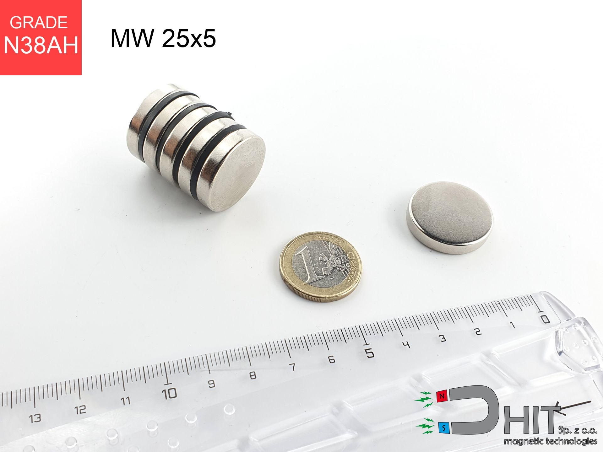

MW 25x5 / N38AH - cylindrical magnet
cylindrical magnet
Catalog no 010501
GTIN/EAN: 5906301814993
Diameter Ø
25 mm [±0,1 mm]
Height
5 mm [±0,1 mm]
Weight
18.41 g
Magnetization Direction
↑ axial
Load capacity
7.29 kg / 71.47 N
Magnetic Induction
219.99 mT / 2200 Gs
Coating
[NiCuNi] Nickel
16.68 ZŁ with VAT / pcs + price for transport
13.56 ZŁ net + 23% VAT / pcs
bulk discounts:
Need more?
Give us a call
+48 22 499 98 98
or send us a note through
form
our website.
Specifications along with shape of a neodymium magnet can be reviewed with our
force calculator.
Orders placed before 14:00 will be shipped the same business day.
Technical details - MW 25x5 / N38AH - cylindrical magnet
Specification / characteristics - MW 25x5 / N38AH - cylindrical magnet
| properties | values |
|---|---|
| Cat. no. | 010501 |
| GTIN/EAN | 5906301814993 |
| Production/Distribution | Dhit sp. z o.o. |
| Country of origin | Poland / China / Germany |
| Customs code | 85059029 |
| Diameter Ø | 25 mm [±0,1 mm] |
| Height | 5 mm [±0,1 mm] |
| Weight | 18.41 g |
| Magnetization Direction | ↑ axial |
| Load capacity ~ ? | 7.29 kg / 71.47 N |
| Magnetic Induction ~ ? | 219.99 mT / 2200 Gs |
| Coating | [NiCuNi] Nickel |
| Manufacturing Tolerance | ±0.1 mm |
Magnetic properties of material N38AH
| properties | values | units |
|---|---|---|
| remenance Br [min. - max.] ? | 12.2-12.5 | kGs |
| remenance Br [min. - max.] ? | 1120-1250 | mT |
| coercivity bHc ? | ≥ 11.3 | kOe |
| coercivity bHc ? | ≥ 899 | kA/m |
| actual internal force iHc | ≥ 33 | kOe |
| actual internal force iHc | ≥ 2624 | kA/m |
| energy density [min. - max.] ? | 36-39 | BH max MGOe |
| energy density [min. - max.] ? | 287-310 | BH max KJ/m |
| max. temperature ? | ≤ 230 | °C |
Physical properties of sintered neodymium magnets Nd2Fe14B at 20°C
| properties | values | units |
|---|---|---|
| Vickers hardness | ≥550 | Hv |
| Density | ≥7.4 | g/cm3 |
| Curie Temperature TC | 312 - 380 | °C |
| Curie Temperature TF | 593 - 716 | °F |
| Specific resistance | 150 | μΩ⋅cm |
| Bending strength | 250 | MPa |
| Compressive strength | 1000~1100 | MPa |
| Thermal expansion parallel (∥) to orientation (M) | (3-4) x 10-6 | °C-1 |
| Thermal expansion perpendicular (⊥) to orientation (M) | -(1-3) x 10-6 | °C-1 |
| Young's modulus | 1.7 x 10⁴ | kg/mm² |
Physical analysis of the magnet - technical parameters
These information represent the result of a mathematical analysis. Results are based on models for the class Nd2Fe14B. Actual performance might slightly differ. Use these calculations as a preliminary roadmap for designers.
Table 1: Static pull force (pull vs distance) - power drop
MW 25x5 / N38AH
| Distance (mm) | Induction (Gauss) / mT | Pull Force (kg/lbs/g/N) | Risk Status |
|---|---|---|---|
| 0 mm |
2292 Gs
229.2 mT
|
7.29 kg / 16.07 LBS
7290.0 g / 71.5 N
|
warning |
| 1 mm |
2180 Gs
218.0 mT
|
6.59 kg / 14.53 LBS
6591.0 g / 64.7 N
|
warning |
| 2 mm |
2042 Gs
204.2 mT
|
5.78 kg / 12.75 LBS
5782.0 g / 56.7 N
|
warning |
| 3 mm |
1888 Gs
188.8 mT
|
4.94 kg / 10.90 LBS
4942.8 g / 48.5 N
|
warning |
| 5 mm |
1564 Gs
156.4 mT
|
3.39 kg / 7.48 LBS
3394.1 g / 33.3 N
|
warning |
| 10 mm |
886 Gs
88.6 mT
|
1.09 kg / 2.40 LBS
1089.7 g / 10.7 N
|
weak grip |
| 15 mm |
493 Gs
49.3 mT
|
0.34 kg / 0.74 LBS
336.7 g / 3.3 N
|
weak grip |
| 20 mm |
287 Gs
28.7 mT
|
0.11 kg / 0.25 LBS
114.0 g / 1.1 N
|
weak grip |
| 30 mm |
115 Gs
11.5 mT
|
0.02 kg / 0.04 LBS
18.4 g / 0.2 N
|
weak grip |
| 50 mm |
31 Gs
3.1 mT
|
0.00 kg / 0.00 LBS
1.3 g / 0.0 N
|
weak grip |
Table 2: Vertical hold (wall)
MW 25x5 / N38AH
| Distance (mm) | Friction coefficient | Pull Force (kg/lbs/g/N) |
|---|---|---|
| 0 mm | Stal (~0.2) |
1.46 kg / 3.21 LBS
1458.0 g / 14.3 N
|
| 1 mm | Stal (~0.2) |
1.32 kg / 2.91 LBS
1318.0 g / 12.9 N
|
| 2 mm | Stal (~0.2) |
1.16 kg / 2.55 LBS
1156.0 g / 11.3 N
|
| 3 mm | Stal (~0.2) |
0.99 kg / 2.18 LBS
988.0 g / 9.7 N
|
| 5 mm | Stal (~0.2) |
0.68 kg / 1.49 LBS
678.0 g / 6.7 N
|
| 10 mm | Stal (~0.2) |
0.22 kg / 0.48 LBS
218.0 g / 2.1 N
|
| 15 mm | Stal (~0.2) |
0.07 kg / 0.15 LBS
68.0 g / 0.7 N
|
| 20 mm | Stal (~0.2) |
0.02 kg / 0.05 LBS
22.0 g / 0.2 N
|
| 30 mm | Stal (~0.2) |
0.00 kg / 0.01 LBS
4.0 g / 0.0 N
|
| 50 mm | Stal (~0.2) |
0.00 kg / 0.00 LBS
0.0 g / 0.0 N
|
Table 3: Vertical assembly (sliding) - vertical pull
MW 25x5 / N38AH
| Surface type | Friction coefficient / % Mocy | Max load (kg/lbs/g/N) |
|---|---|---|
| Raw steel |
µ = 0.3
30% Nominalnej Siły
|
2.19 kg / 4.82 LBS
2187.0 g / 21.5 N
|
| Painted steel (standard) |
µ = 0.2
20% Nominalnej Siły
|
1.46 kg / 3.21 LBS
1458.0 g / 14.3 N
|
| Oily/slippery steel |
µ = 0.1
10% Nominalnej Siły
|
0.73 kg / 1.61 LBS
729.0 g / 7.2 N
|
| Magnet with anti-slip rubber |
µ = 0.5
50% Nominalnej Siły
|
3.65 kg / 8.04 LBS
3645.0 g / 35.8 N
|
Table 4: Material efficiency (substrate influence) - power losses
MW 25x5 / N38AH
| Steel thickness (mm) | % power | Real pull force (kg/lbs/g/N) |
|---|---|---|
| 0.5 mm |
|
0.73 kg / 1.61 LBS
729.0 g / 7.2 N
|
| 1 mm |
|
1.82 kg / 4.02 LBS
1822.5 g / 17.9 N
|
| 2 mm |
|
3.65 kg / 8.04 LBS
3645.0 g / 35.8 N
|
| 3 mm |
|
5.47 kg / 12.05 LBS
5467.5 g / 53.6 N
|
| 5 mm |
|
7.29 kg / 16.07 LBS
7290.0 g / 71.5 N
|
| 10 mm |
|
7.29 kg / 16.07 LBS
7290.0 g / 71.5 N
|
| 11 mm |
|
7.29 kg / 16.07 LBS
7290.0 g / 71.5 N
|
| 12 mm |
|
7.29 kg / 16.07 LBS
7290.0 g / 71.5 N
|
Table 5: Working in heat (stability) - thermal limit
MW 25x5 / N38AH
| Ambient temp. (°C) | Power loss | Remaining pull (kg/lbs/g/N) | Status |
|---|---|---|---|
| 20 °C | 0.0% |
7.29 kg / 16.07 LBS
7290.0 g / 71.5 N
|
OK |
| 80 °C | -6.6% |
6.81 kg / 15.01 LBS
6808.9 g / 66.8 N
|
|
| 150 °C | -14.3% |
6.25 kg / 13.77 LBS
6247.5 g / 61.3 N
|
|
| 200 °C | -19.8% |
5.85 kg / 12.89 LBS
5846.6 g / 57.4 N
|
|
| 230 °C | -23.1% |
5.61 kg / 12.36 LBS
5606.0 g / 55.0 N
|
|
| 250 °C | -45.3% |
3.99 kg / 8.79 LBS
3987.6 g / 39.1 N
|
Table 6: Two magnets (attraction) - field collision
MW 25x5 / N38AH
| Gap (mm) | Attraction (kg/lbs) (N-S) | Lateral Force (kg/lbs/g/N) | Repulsion (kg/lbs) (N-N) |
|---|---|---|---|
| 0 mm |
15.90 kg / 35.06 LBS
3 855 Gs
|
2.39 kg / 5.26 LBS
2385 g / 23.4 N
|
N/A |
| 1 mm |
15.19 kg / 33.48 LBS
4 480 Gs
|
2.28 kg / 5.02 LBS
2278 g / 22.3 N
|
13.67 kg / 30.13 LBS
~0 Gs
|
| 2 mm |
14.38 kg / 31.70 LBS
4 359 Gs
|
2.16 kg / 4.75 LBS
2157 g / 21.2 N
|
12.94 kg / 28.53 LBS
~0 Gs
|
| 3 mm |
13.51 kg / 29.79 LBS
4 226 Gs
|
2.03 kg / 4.47 LBS
2027 g / 19.9 N
|
12.16 kg / 26.81 LBS
~0 Gs
|
| 5 mm |
11.70 kg / 25.79 LBS
3 932 Gs
|
1.75 kg / 3.87 LBS
1755 g / 17.2 N
|
10.53 kg / 23.21 LBS
~0 Gs
|
| 10 mm |
7.40 kg / 16.32 LBS
3 128 Gs
|
1.11 kg / 2.45 LBS
1111 g / 10.9 N
|
6.66 kg / 14.69 LBS
~0 Gs
|
| 20 mm |
2.38 kg / 5.24 LBS
1 773 Gs
|
0.36 kg / 0.79 LBS
357 g / 3.5 N
|
2.14 kg / 4.72 LBS
~0 Gs
|
| 50 mm |
0.09 kg / 0.21 LBS
354 Gs
|
0.01 kg / 0.03 LBS
14 g / 0.1 N
|
0.09 kg / 0.19 LBS
~0 Gs
|
| 60 mm |
0.04 kg / 0.09 LBS
231 Gs
|
0.01 kg / 0.01 LBS
6 g / 0.1 N
|
0.04 kg / 0.08 LBS
~0 Gs
|
| 70 mm |
0.02 kg / 0.04 LBS
157 Gs
|
0.00 kg / 0.01 LBS
3 g / 0.0 N
|
0.02 kg / 0.04 LBS
~0 Gs
|
| 80 mm |
0.01 kg / 0.02 LBS
112 Gs
|
0.00 kg / 0.00 LBS
1 g / 0.0 N
|
0.00 kg / 0.00 LBS
~0 Gs
|
| 90 mm |
0.01 kg / 0.01 LBS
82 Gs
|
0.00 kg / 0.00 LBS
1 g / 0.0 N
|
0.00 kg / 0.00 LBS
~0 Gs
|
| 100 mm |
0.00 kg / 0.01 LBS
62 Gs
|
0.00 kg / 0.00 LBS
0 g / 0.0 N
|
0.00 kg / 0.00 LBS
~0 Gs
|
Table 7: Safety (HSE) (implants) - precautionary measures
MW 25x5 / N38AH
| Object / Device | Limit (Gauss) / mT | Safe distance |
|---|---|---|
| Pacemaker | 5 Gs (0.5 mT) | 10.0 cm |
| Hearing aid | 10 Gs (1.0 mT) | 7.5 cm |
| Timepiece | 20 Gs (2.0 mT) | 6.0 cm |
| Phone / Smartphone | 40 Gs (4.0 mT) | 5.0 cm |
| Remote | 50 Gs (5.0 mT) | 4.5 cm |
| Payment card | 400 Gs (40.0 mT) | 2.0 cm |
| HDD hard drive | 600 Gs (60.0 mT) | 1.5 cm |
Table 8: Collisions (cracking risk) - collision effects
MW 25x5 / N38AH
| Start from (mm) | Speed (km/h) | Energy (J) | Predicted outcome |
|---|---|---|---|
| 10 mm |
21.86 km/h
(6.07 m/s)
|
0.34 J | |
| 30 mm |
34.81 km/h
(9.67 m/s)
|
0.86 J | |
| 50 mm |
44.88 km/h
(12.47 m/s)
|
1.43 J | |
| 100 mm |
63.46 km/h
(17.63 m/s)
|
2.86 J |
Table 9: Corrosion resistance
MW 25x5 / N38AH
| Technical parameter | Value / Description |
|---|---|
| Coating type | [NiCuNi] Nickel |
| Layer structure | Nickel - Copper - Nickel |
| Layer thickness | 10-20 µm |
| Salt spray test (SST) ? | 24 h |
| Recommended environment | Indoors only (dry) |
Table 10: Electrical data (Pc)
MW 25x5 / N38AH
| Parameter | Value | SI Unit / Description |
|---|---|---|
| Magnetic Flux | 13 054 Mx | 130.5 µWb |
| Pc Coefficient | 0.29 | Low (Flat) |
Table 11: Hydrostatics and buoyancy
MW 25x5 / N38AH
| Environment | Effective steel pull | Effect |
|---|---|---|
| Air (land) | 7.29 kg | Standard |
| Water (riverbed) |
8.35 kg
(+1.06 kg buoyancy gain)
|
+14.5% |
1. Shear force
*Warning: On a vertical surface, the magnet holds only ~20% of its nominal pull.
2. Steel thickness impact
*Thin metal sheet (e.g. 0.5mm PC case) drastically reduces the holding force.
3. Temperature resistance
*For N38 material, the safety limit is 80°C.
4. Demagnetization curve and operating point (B-H)
chart generated for the permeance coefficient Pc (Permeance Coefficient) = 0.29
The chart above illustrates the magnetic characteristics of the material within the second quadrant of the hysteresis loop. The solid red line represents the demagnetization curve (material potential), while the dashed blue line is the load line based on the magnet's geometry. The Pc (Permeance Coefficient), also known as the load line slope, is a dimensionless value that describes the relationship between the magnet's shape and its magnetic stability. The intersection of these two lines (the black dot) is the operating point — it determines the actual magnetic flux density generated by the magnet in this specific configuration. A higher Pc value means the magnet is more 'slender' (tall relative to its area), resulting in a higher operating point and better resistance to irreversible demagnetization caused by external fields or temperature. A value of 0.42 is relatively low (typical for flat magnets), meaning the operating point is closer to the 'knee' of the curve — caution is advised when operating at temperatures near the maximum limit to avoid strength loss.
Material specification
| iron (Fe) | 64% – 68% |
| neodymium (Nd) | 29% – 32% |
| boron (B) | 1.1% – 1.2% |
| dysprosium (Dy) | 0.5% – 2.0% |
| coating (Ni-Cu-Ni) | < 0.05% |
Environmental data
| recyclability (EoL) | 100% |
| recycled raw materials | ~10% (pre-cons) |
| carbon footprint | low / zredukowany |
| waste code (EWC) | 16 02 16 |
View more offers
![UMGZ 36x18x8 [M6] GZ / N38 - magnetic holder external thread](https://cdn3.dhit.pl/graphics/products/um-36x18x8-m8-gz-xiv.jpg "UMGZ 36x18x8 [M6] GZ / N38 - magnetic holder external thread")
![BM 700x180x75 [8xM10] - magnetic beam](https://cdn3.dhit.pl/graphics/blank.jpg "BM 700x180x75 [8xM10] - magnetic beam")
![UMGGZ 43x6 [M6] GZ / N38 - rubber magnetic holder external thread](https://cdn3.dhit.pl/graphics/products/umg-43x6-m6-gz-miw.jpg "UMGGZ 43x6 [M6] GZ / N38 - rubber magnetic holder external thread")
![UMGGW 66x8.5 [M8] GW / N38 - magnetic holder rubber internal thread](https://cdn3.dhit.pl/graphics/products/umg-66x8.5-m6-gw-wud.jpg "UMGGW 66x8.5 [M8] GW / N38 - magnetic holder rubber internal thread")
Advantages and disadvantages of neodymium magnets.
Strengths
- They virtually do not lose strength, because even after ten years the decline in efficiency is only ~1% (according to literature),
- They have excellent resistance to magnetism drop when exposed to opposing magnetic fields,
- By using a shiny layer of nickel, the element has an aesthetic look,
- Neodymium magnets create maximum magnetic induction on a small surface, which ensures high operational effectiveness,
- Thanks to resistance to high temperature, they are capable of working (depending on the shape) even at temperatures up to 230°C and higher...
- Thanks to freedom in designing and the capacity to adapt to unusual requirements,
- Key role in advanced technology sectors – they are used in HDD drives, motor assemblies, medical equipment, as well as complex engineering applications.
- Compactness – despite small sizes they offer powerful magnetic field, making them ideal for precision applications
Limitations
- To avoid cracks upon strong impacts, we suggest using special steel housings. Such a solution secures the magnet and simultaneously increases its durability.
- NdFeB magnets lose power when exposed to high temperatures. After reaching 80°C, many of them experience permanent drop of strength (a factor is the shape as well as dimensions of the magnet). We offer magnets specially adapted to work at temperatures up to 230°C marked [AH], which are very resistant to heat
- They rust in a humid environment - during use outdoors we recommend using waterproof magnets e.g. in rubber, plastic
- Limited ability of creating nuts in the magnet and complicated forms - recommended is cover - magnet mounting.
- Health risk related to microscopic parts of magnets can be dangerous, in case of ingestion, which becomes key in the context of child safety. Furthermore, small components of these devices are able to be problematic in diagnostics medical when they are in the body.
- Higher cost of purchase is a significant factor to consider compared to ceramic magnets, especially in budget applications
Holding force characteristics
Best holding force of the magnet in ideal parameters – what it depends on?
- on a plate made of structural steel, optimally conducting the magnetic flux
- possessing a massiveness of at least 10 mm to avoid saturation
- with a plane cleaned and smooth
- without the slightest air gap between the magnet and steel
- during detachment in a direction perpendicular to the plane
- at ambient temperature approx. 20 degrees Celsius
Practical aspects of lifting capacity – factors
- Gap (betwixt the magnet and the plate), because even a tiny clearance (e.g. 0.5 mm) results in a reduction in force by up to 50% (this also applies to varnish, corrosion or debris).
- Loading method – catalog parameter refers to detachment vertically. When applying parallel force, the magnet holds significantly lower power (often approx. 20-30% of maximum force).
- Plate thickness – too thin steel causes magnetic saturation, causing part of the flux to be escaped into the air.
- Material type – ideal substrate is pure iron steel. Hardened steels may attract less.
- Surface finish – full contact is possible only on smooth steel. Any scratches and bumps create air cushions, weakening the magnet.
- Temperature influence – hot environment weakens pulling force. Exceeding the limit temperature can permanently damage the magnet.
Lifting capacity testing was conducted on a smooth plate of optimal thickness, under perpendicular forces, in contrast under parallel forces the lifting capacity is smaller. Moreover, even a minimal clearance between the magnet’s surface and the plate decreases the holding force.
Safe handling of NdFeB magnets
Powerful field
Before starting, check safety instructions. Sudden snapping can break the magnet or injure your hand. Be predictive.
Compass and GPS
Note: rare earth magnets generate a field that confuses sensitive sensors. Maintain a safe distance from your phone, device, and GPS.
Dust is flammable
Mechanical processing of neodymium magnets carries a risk of fire hazard. Neodymium dust oxidizes rapidly with oxygen and is hard to extinguish.
Warning for allergy sufferers
Studies show that nickel (standard magnet coating) is a strong allergen. For allergy sufferers, prevent touching magnets with bare hands and choose encased magnets.
Do not overheat magnets
Avoid heat. NdFeB magnets are sensitive to heat. If you require operation above 80°C, ask us about HT versions (H, SH, UH).
Serious injuries
Big blocks can smash fingers in a fraction of a second. Do not put your hand between two strong magnets.
Shattering risk
Watch out for shards. Magnets can fracture upon uncontrolled impact, ejecting shards into the air. Eye protection is mandatory.
Electronic hazard
Do not bring magnets near a wallet, computer, or screen. The magnetism can destroy these devices and wipe information from cards.
Keep away from children
NdFeB magnets are not suitable for play. Accidental ingestion of a few magnets can lead to them pinching intestinal walls, which poses a severe health hazard and requires urgent medical intervention.
Life threat
People with a pacemaker must maintain an safe separation from magnets. The magnetic field can disrupt the functioning of the implant.
Tabela kosztu i czasu dostawy
Płatność przed wysyłką:

GLS kurier
Przesyłka będzie u Ciebie za 2-3 dni
14.99 ZŁ

InPost Paczkomaty 24/7
Przesyłka będzie u Ciebie za 1-2 dni
12.30 ZŁ
Płatność przy odbiorze (pobranie):
GLS kurier
Przesyłka będzie u Ciebie za 1-2 dni
23.00 ZŁ
Rate the product
Your rating