

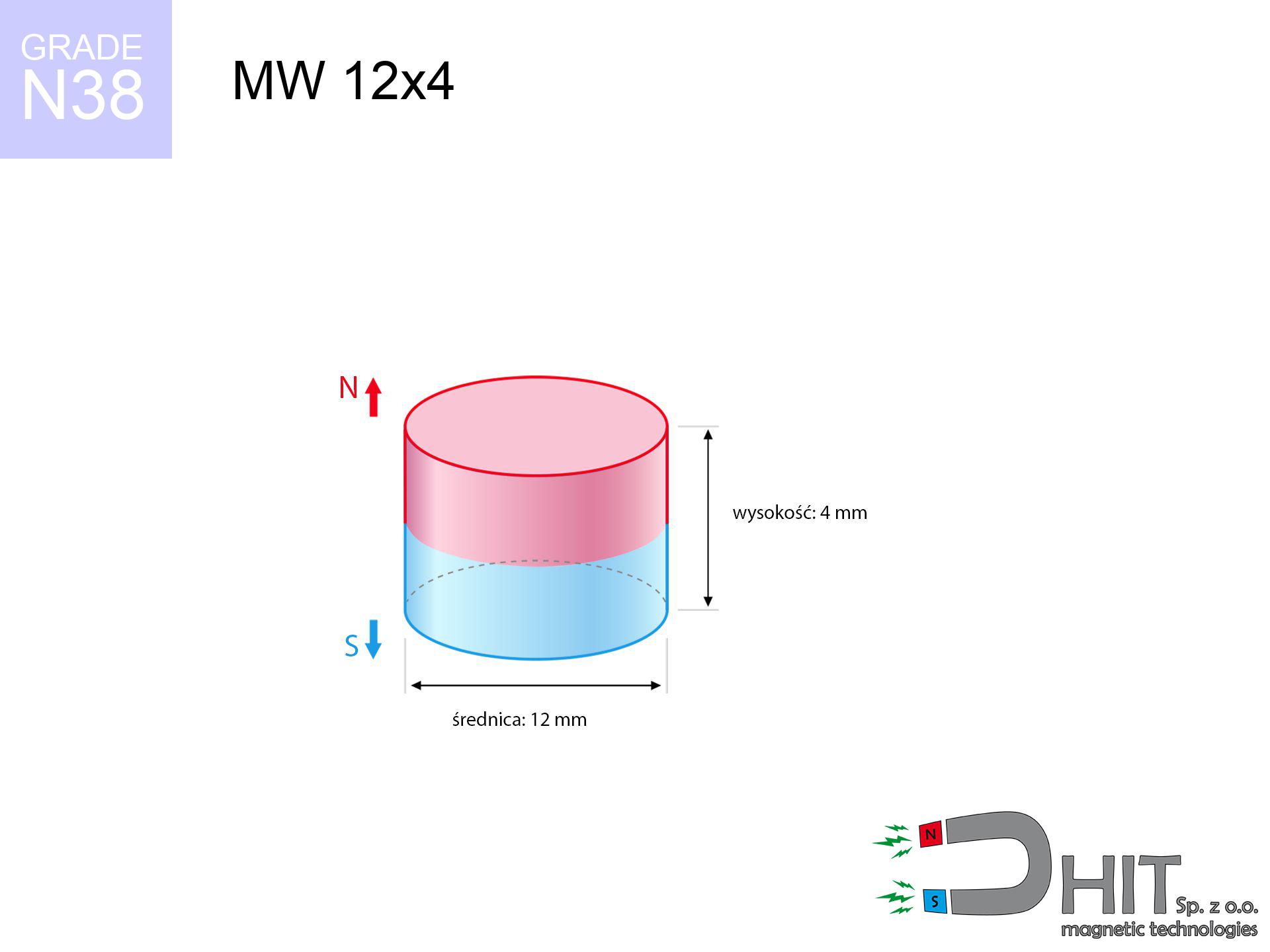
MW 12x4 / N38 - cylindrical magnet
cylindrical magnet
Catalog no 010019
GTIN/EAN: 5906301810186
Diameter Ø
12 mm [±0,1 mm]
Height
4 mm [±0,1 mm]
Weight
3.39 g
Magnetization Direction
↑ axial
Load capacity
3.45 kg / 33.81 N
Magnetic Induction
343.64 mT / 3436 Gs
Coating
[NiCuNi] Nickel
1.353 ZŁ with VAT / pcs + price for transport
1.100 ZŁ net + 23% VAT / pcs
bulk discounts:
Need more?Engineering report for this magnet
Full PDF analysis: pull and shear force, effect of distance, temperature and plate thickness, safety distances and the demagnetization curve.
Give us a call
+48 22 499 98 98
or drop us a message using
our online form
the contact form page.
Strength and form of magnetic components can be analyzed with our
magnetic calculator.
Orders submitted before 14:00 will be dispatched today!
Product card - MW 12x4 / N38 - cylindrical magnet
Specification / characteristics - MW 12x4 / N38 - cylindrical magnet
| properties | values |
|---|---|
| Cat. no. | 010019 |
| GTIN/EAN | 5906301810186 |
| Production/Distribution | Dhit sp. z o.o. |
| Country of origin | Poland / China / Germany |
| Customs code | 85059029 |
| Diameter Ø | 12 mm [±0,1 mm] |
| Height | 4 mm [±0,1 mm] |
| Weight | 3.39 g |
| Magnetization Direction | ↑ axial |
| Load capacity ~ ? | 3.45 kg / 33.81 N |
| Magnetic Induction ~ ? | 343.64 mT / 3436 Gs |
| Coating | [NiCuNi] Nickel |
| Manufacturing Tolerance | ±0.1 mm |
Magnetic properties of material N38
| properties | values | units |
|---|---|---|
| remenance Br [min. - max.] ? | 12.2-12.6 | kGs |
| remenance Br [min. - max.] ? | 1220-1260 | mT |
| coercivity bHc ? | 10.8-11.5 | kOe |
| coercivity bHc ? | 860-915 | kA/m |
| actual internal force iHc | ≥ 12 | kOe |
| actual internal force iHc | ≥ 955 | kA/m |
| energy density [min. - max.] ? | 36-38 | BH max MGOe |
| energy density [min. - max.] ? | 287-303 | BH max KJ/m |
| max. temperature ? | ≤ 80 | °C |
Physical properties of sintered neodymium magnets Nd2Fe14B at 20°C
| properties | values | units |
|---|---|---|
| Vickers hardness | ≥550 | Hv |
| Density | ≥7.4 | g/cm3 |
| Curie Temperature TC | 312 - 380 | °C |
| Curie Temperature TF | 593 - 716 | °F |
| Specific resistance | 150 | μΩ⋅cm |
| Bending strength | 250 | MPa |
| Compressive strength | 1000~1100 | MPa |
| Thermal expansion parallel (∥) to orientation (M) | (3-4) x 10-6 | °C-1 |
| Thermal expansion perpendicular (⊥) to orientation (M) | -(1-3) x 10-6 | °C-1 |
| Young's modulus | 1.7 x 10⁴ | kg/mm² |
Technical simulation of the assembly - report
These data are the outcome of a mathematical calculation. Values were calculated on models for the material Nd2Fe14B. Actual parameters may differ. Treat these calculations as a preliminary roadmap during assembly planning.
Table 1: Static force (force vs gap) - characteristics
MW 12x4 / N38
| Distance (mm) | Induction (Gauss) / mT | Pull Force (kg/lbs/g/N) | Risk Status |
|---|---|---|---|
| 0 mm |
3435 Gs
343.5 mT
|
3.45 kg / 7.61 LBS
3450.0 g / 33.8 N
|
medium risk |
| 1 mm |
2950 Gs
295.0 mT
|
2.54 kg / 5.61 LBS
2544.7 g / 25.0 N
|
medium risk |
| 2 mm |
2423 Gs
242.3 mT
|
1.72 kg / 3.79 LBS
1717.5 g / 16.8 N
|
weak grip |
| 3 mm |
1935 Gs
193.5 mT
|
1.09 kg / 2.41 LBS
1094.6 g / 10.7 N
|
weak grip |
| 5 mm |
1190 Gs
119.0 mT
|
0.41 kg / 0.91 LBS
413.8 g / 4.1 N
|
weak grip |
| 10 mm |
382 Gs
38.2 mT
|
0.04 kg / 0.09 LBS
42.7 g / 0.4 N
|
weak grip |
| 15 mm |
156 Gs
15.6 mT
|
0.01 kg / 0.02 LBS
7.1 g / 0.1 N
|
weak grip |
| 20 mm |
76 Gs
7.6 mT
|
0.00 kg / 0.00 LBS
1.7 g / 0.0 N
|
weak grip |
| 30 mm |
26 Gs
2.6 mT
|
0.00 kg / 0.00 LBS
0.2 g / 0.0 N
|
weak grip |
| 50 mm |
6 Gs
0.6 mT
|
0.00 kg / 0.00 LBS
0.0 g / 0.0 N
|
weak grip |
Table 2: Shear capacity (vertical surface)
MW 12x4 / N38
| Distance (mm) | Friction coefficient | Pull Force (kg/lbs/g/N) |
|---|---|---|
| 0 mm | Stal (~0.2) |
0.69 kg / 1.52 LBS
690.0 g / 6.8 N
|
| 1 mm | Stal (~0.2) |
0.51 kg / 1.12 LBS
508.0 g / 5.0 N
|
| 2 mm | Stal (~0.2) |
0.34 kg / 0.76 LBS
344.0 g / 3.4 N
|
| 3 mm | Stal (~0.2) |
0.22 kg / 0.48 LBS
218.0 g / 2.1 N
|
| 5 mm | Stal (~0.2) |
0.08 kg / 0.18 LBS
82.0 g / 0.8 N
|
| 10 mm | Stal (~0.2) |
0.01 kg / 0.02 LBS
8.0 g / 0.1 N
|
| 15 mm | Stal (~0.2) |
0.00 kg / 0.00 LBS
2.0 g / 0.0 N
|
| 20 mm | Stal (~0.2) |
0.00 kg / 0.00 LBS
0.0 g / 0.0 N
|
| 30 mm | Stal (~0.2) |
0.00 kg / 0.00 LBS
0.0 g / 0.0 N
|
| 50 mm | Stal (~0.2) |
0.00 kg / 0.00 LBS
0.0 g / 0.0 N
|
Table 3: Wall mounting (sliding) - behavior on slippery surfaces
MW 12x4 / N38
| Surface type | Friction coefficient / % Mocy | Max load (kg/lbs/g/N) |
|---|---|---|
| Raw steel |
µ = 0.3
30% Nominalnej Siły
|
1.04 kg / 2.28 LBS
1035.0 g / 10.2 N
|
| Painted steel (standard) |
µ = 0.2
20% Nominalnej Siły
|
0.69 kg / 1.52 LBS
690.0 g / 6.8 N
|
| Oily/slippery steel |
µ = 0.1
10% Nominalnej Siły
|
0.35 kg / 0.76 LBS
345.0 g / 3.4 N
|
| Magnet with anti-slip rubber |
µ = 0.5
50% Nominalnej Siły
|
1.73 kg / 3.80 LBS
1725.0 g / 16.9 N
|
Table 4: Steel thickness (saturation) - sheet metal selection
MW 12x4 / N38
| Steel thickness (mm) | % power | Real pull force (kg/lbs/g/N) |
|---|---|---|
| 0.5 mm |
|
0.35 kg / 0.76 LBS
345.0 g / 3.4 N
|
| 1 mm |
|
0.86 kg / 1.90 LBS
862.5 g / 8.5 N
|
| 2 mm |
|
1.73 kg / 3.80 LBS
1725.0 g / 16.9 N
|
| 3 mm |
|
2.59 kg / 5.70 LBS
2587.5 g / 25.4 N
|
| 5 mm |
|
3.45 kg / 7.61 LBS
3450.0 g / 33.8 N
|
| 10 mm |
|
3.45 kg / 7.61 LBS
3450.0 g / 33.8 N
|
| 11 mm |
|
3.45 kg / 7.61 LBS
3450.0 g / 33.8 N
|
| 12 mm |
|
3.45 kg / 7.61 LBS
3450.0 g / 33.8 N
|
Table 5: Thermal resistance (material behavior) - thermal limit
MW 12x4 / N38
| Ambient temp. (°C) | Power loss | Remaining pull (kg/lbs/g/N) | Status |
|---|---|---|---|
| 20 °C | 0.0% |
3.45 kg / 7.61 LBS
3450.0 g / 33.8 N
|
OK |
| 40 °C | -2.2% |
3.37 kg / 7.44 LBS
3374.1 g / 33.1 N
|
OK |
| 60 °C | -4.4% |
3.30 kg / 7.27 LBS
3298.2 g / 32.4 N
|
|
| 80 °C | -6.6% |
3.22 kg / 7.10 LBS
3222.3 g / 31.6 N
|
|
| 100 °C | -28.8% |
2.46 kg / 5.42 LBS
2456.4 g / 24.1 N
|
Table 6: Magnet-Magnet interaction (repulsion) - field collision
MW 12x4 / N38
| Gap (mm) | Attraction (kg/lbs) (N-S) | Shear Force (kg/lbs/g/N) | Repulsion (kg/lbs) (N-N) |
|---|---|---|---|
| 0 mm |
8.23 kg / 18.13 LBS
4 952 Gs
|
1.23 kg / 2.72 LBS
1234 g / 12.1 N
|
N/A |
| 1 mm |
7.16 kg / 15.79 LBS
6 410 Gs
|
1.07 kg / 2.37 LBS
1074 g / 10.5 N
|
6.45 kg / 14.21 LBS
~0 Gs
|
| 2 mm |
6.07 kg / 13.38 LBS
5 900 Gs
|
0.91 kg / 2.01 LBS
910 g / 8.9 N
|
5.46 kg / 12.04 LBS
~0 Gs
|
| 3 mm |
5.03 kg / 11.09 LBS
5 372 Gs
|
0.75 kg / 1.66 LBS
754 g / 7.4 N
|
4.53 kg / 9.98 LBS
~0 Gs
|
| 5 mm |
3.29 kg / 7.25 LBS
4 342 Gs
|
0.49 kg / 1.09 LBS
493 g / 4.8 N
|
2.96 kg / 6.52 LBS
~0 Gs
|
| 10 mm |
0.99 kg / 2.18 LBS
2 379 Gs
|
0.15 kg / 0.33 LBS
148 g / 1.5 N
|
0.89 kg / 1.96 LBS
~0 Gs
|
| 20 mm |
0.10 kg / 0.22 LBS
764 Gs
|
0.02 kg / 0.03 LBS
15 g / 0.1 N
|
0.09 kg / 0.20 LBS
~0 Gs
|
| 50 mm |
0.00 kg / 0.00 LBS
85 Gs
|
0.00 kg / 0.00 LBS
0 g / 0.0 N
|
0.00 kg / 0.00 LBS
~0 Gs
|
| 60 mm |
0.00 kg / 0.00 LBS
52 Gs
|
0.00 kg / 0.00 LBS
0 g / 0.0 N
|
0.00 kg / 0.00 LBS
~0 Gs
|
| 70 mm |
0.00 kg / 0.00 LBS
34 Gs
|
0.00 kg / 0.00 LBS
0 g / 0.0 N
|
0.00 kg / 0.00 LBS
~0 Gs
|
| 80 mm |
0.00 kg / 0.00 LBS
23 Gs
|
0.00 kg / 0.00 LBS
0 g / 0.0 N
|
0.00 kg / 0.00 LBS
~0 Gs
|
| 90 mm |
0.00 kg / 0.00 LBS
17 Gs
|
0.00 kg / 0.00 LBS
0 g / 0.0 N
|
0.00 kg / 0.00 LBS
~0 Gs
|
| 100 mm |
0.00 kg / 0.00 LBS
12 Gs
|
0.00 kg / 0.00 LBS
0 g / 0.0 N
|
0.00 kg / 0.00 LBS
~0 Gs
|
Table 7: Hazards (electronics) - precautionary measures
MW 12x4 / N38
| Object / Device | Limit (Gauss) / mT | Safe distance |
|---|---|---|
| Pacemaker | 5 Gs (0.5 mT) | 5.5 cm |
| Hearing aid | 10 Gs (1.0 mT) | 4.5 cm |
| Timepiece | 20 Gs (2.0 mT) | 3.5 cm |
| Phone / Smartphone | 40 Gs (4.0 mT) | 3.0 cm |
| Remote | 50 Gs (5.0 mT) | 2.5 cm |
| Payment card | 400 Gs (40.0 mT) | 1.0 cm |
| HDD hard drive | 600 Gs (60.0 mT) | 1.0 cm |
Table 8: Impact energy (kinetic energy) - collision effects
MW 12x4 / N38
| Start from (mm) | Speed (km/h) | Energy (J) | Predicted outcome |
|---|---|---|---|
| 10 mm |
32.42 km/h
(9.01 m/s)
|
0.14 J | |
| 30 mm |
55.73 km/h
(15.48 m/s)
|
0.41 J | |
| 50 mm |
71.94 km/h
(19.98 m/s)
|
0.68 J | |
| 100 mm |
101.74 km/h
(28.26 m/s)
|
1.35 J |
Table 9: Surface protection spec
MW 12x4 / N38
| Technical parameter | Value / Description |
|---|---|
| Coating type | [NiCuNi] Nickel |
| Layer structure | Nickel - Copper - Nickel |
| Layer thickness | 10-20 µm |
| Salt spray test (SST) ? | 24 h |
| Recommended environment | Indoors only (dry) |
Table 10: Construction data (Pc)
MW 12x4 / N38
| Parameter | Value | SI Unit / Description |
|---|---|---|
| Magnetic Flux | 4 114 Mx | 41.1 µWb |
| Pc Coefficient | 0.44 | Low (Flat) |
Table 11: Hydrostatics and buoyancy
MW 12x4 / N38
| Environment | Effective steel pull | Effect |
|---|---|---|
| Air (land) | 3.45 kg | Standard |
| Water (riverbed) |
3.95 kg
(+0.50 kg buoyancy gain)
|
+14.5% |
1. Vertical hold
*Warning: On a vertical wall, the magnet holds just ~20% of its nominal pull.
2. Efficiency vs thickness
*Thin steel (e.g. computer case) drastically reduces the holding force.
3. Thermal stability
*For standard magnets, the critical limit is 80°C.
4. Demagnetization curve and operating point (B-H)
chart generated for the permeance coefficient Pc (Permeance Coefficient) = 0.44
The chart above illustrates the magnetic characteristics of the material within the second quadrant of the hysteresis loop. The solid red line represents the demagnetization curve (material potential), while the dashed blue line is the load line based on the magnet's geometry. The Pc (Permeance Coefficient), also known as the load line slope, is a dimensionless value that describes the relationship between the magnet's shape and its magnetic stability. The intersection of these two lines (the black dot) is the operating point — it determines the actual magnetic flux density generated by the magnet in this specific configuration. A higher Pc value means the magnet is more 'slender' (tall relative to its area), resulting in a higher operating point and better resistance to irreversible demagnetization caused by external fields or temperature. A value of 0.42 is relatively low (typical for flat magnets), meaning the operating point is closer to the 'knee' of the curve — caution is advised when operating at temperatures near the maximum limit to avoid strength loss.
Chemical composition
| iron (Fe) | 64% – 68% |
| neodymium (Nd) | 29% – 32% |
| boron (B) | 1.1% – 1.2% |
| dysprosium (Dy) | 0.5% – 2.0% |
| coating (Ni-Cu-Ni) | < 0.05% |
Sustainability
| recyclability (EoL) | 100% |
| recycled raw materials | ~10% (pre-cons) |
| carbon footprint | low / zredukowany |
| waste code (EWC) | 16 02 16 |
Other products

![UMGGW 88x8.5 [M6] GW / N38 - magnetic holder rubber internal thread](https://cdn3.dhit.pl/graphics/products/umg-88x8.5-m8-gw-let.jpg "UMGGW 88x8.5 [M6] GW / N38 - magnetic holder rubber internal thread")


Pros as well as cons of rare earth magnets.
Pros
- They do not lose strength, even over around ten years – the decrease in power is only ~1% (according to tests),
- They maintain their magnetic properties even under close interference source,
- In other words, due to the glossy surface of gold, the element looks attractive,
- Magnetic induction on the working layer of the magnet turns out to be maximum,
- Due to their durability and thermal resistance, neodymium magnets are capable of operate (depending on the shape) even at high temperatures reaching 230°C or more...
- Possibility of individual machining as well as optimizing to defined needs,
- Wide application in modern industrial fields – they are used in hard drives, electric drive systems, diagnostic systems, also technologically advanced constructions.
- Thanks to concentrated force, small magnets offer high operating force, with minimal size,
Weaknesses
- At strong impacts they can break, therefore we recommend placing them in steel cases. A metal housing provides additional protection against damage and increases the magnet's durability.
- NdFeB magnets demagnetize when exposed to high temperatures. After reaching 80°C, many of them experience permanent drop of strength (a factor is the shape as well as dimensions of the magnet). We offer magnets specially adapted to work at temperatures up to 230°C marked [AH], which are very resistant to heat
- Due to the susceptibility of magnets to corrosion in a humid environment, we advise using waterproof magnets made of rubber, plastic or other material resistant to moisture, in case of application outdoors
- Limited possibility of creating nuts in the magnet and complex shapes - recommended is casing - magnet mounting.
- Potential hazard related to microscopic parts of magnets are risky, when accidentally swallowed, which gains importance in the context of child safety. Furthermore, small components of these magnets can be problematic in diagnostics medical when they are in the body.
- With large orders the cost of neodymium magnets is a challenge,
Lifting parameters
Maximum holding power of the magnet – what it depends on?
- on a block made of structural steel, optimally conducting the magnetic flux
- with a thickness no less than 10 mm
- characterized by lack of roughness
- under conditions of no distance (surface-to-surface)
- under perpendicular force direction (90-degree angle)
- at temperature room level
Magnet lifting force in use – key factors
- Gap between magnet and steel – even a fraction of a millimeter of separation (caused e.g. by veneer or dirt) diminishes the pulling force, often by half at just 0.5 mm.
- Pull-off angle – remember that the magnet has greatest strength perpendicularly. Under shear forces, the capacity drops drastically, often to levels of 20-30% of the nominal value.
- Metal thickness – thin material does not allow full use of the magnet. Magnetic flux penetrates through instead of converting into lifting capacity.
- Steel grade – ideal substrate is high-permeability steel. Cast iron may attract less.
- Smoothness – full contact is possible only on smooth steel. Rough texture reduce the real contact area, reducing force.
- Temperature – heating the magnet results in weakening of force. It is worth remembering the thermal limit for a given model.
Lifting capacity testing was performed on plates with a smooth surface of optimal thickness, under perpendicular forces, whereas under parallel forces the holding force is lower. Additionally, even a slight gap between the magnet and the plate lowers the holding force.
Precautions when working with neodymium magnets
Demagnetization risk
Control the heat. Heating the magnet to high heat will permanently weaken its properties and strength.
Threat to navigation
Navigation devices and mobile phones are highly sensitive to magnetism. Close proximity with a strong magnet can permanently damage the sensors in your phone.
Data carriers
Do not bring magnets near a wallet, laptop, or screen. The magnetic field can irreversibly ruin these devices and erase data from cards.
Do not drill into magnets
Fire hazard: Neodymium dust is highly flammable. Avoid machining magnets without safety gear as this may cause fire.
Physical harm
Mind your fingers. Two large magnets will join immediately with a force of several hundred kilograms, crushing everything in their path. Exercise extreme caution!
Beware of splinters
Watch out for shards. Magnets can fracture upon uncontrolled impact, launching sharp fragments into the air. Eye protection is mandatory.
Do not underestimate power
Handle magnets consciously. Their immense force can surprise even experienced users. Stay alert and do not underestimate their power.
Medical interference
Warning for patients: Strong magnetic fields affect medical devices. Keep at least 30 cm distance or ask another person to work with the magnets.
Danger to the youngest
NdFeB magnets are not toys. Accidental ingestion of a few magnets can lead to them attracting across intestines, which constitutes a direct threat to life and necessitates urgent medical intervention.
Metal Allergy
It is widely known that nickel (standard magnet coating) is a potent allergen. For allergy sufferers, avoid direct skin contact or choose coated magnets.
Tabela kosztu i czasu dostawy
Płatność przed wysyłką:

GLS kurier
Przesyłka będzie u Ciebie za 2-3 dni
14.99 ZŁ

InPost Paczkomaty 24/7
Przesyłka będzie u Ciebie za 1-2 dni
12.30 ZŁ
Płatność przy odbiorze (pobranie):
GLS kurier
Przesyłka będzie u Ciebie za 1-2 dni
23.00 ZŁ
Rate the product
Your rating