

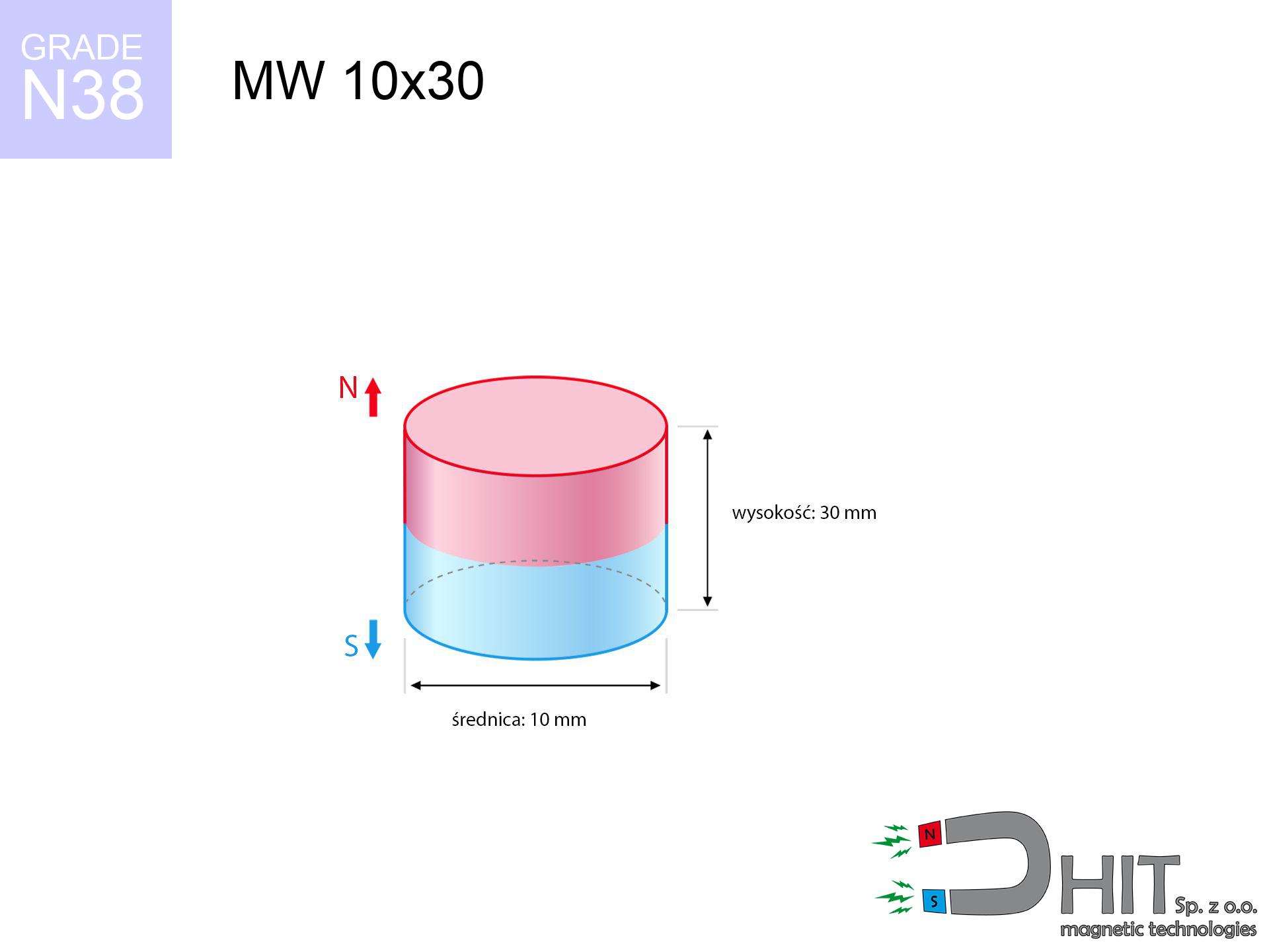
MW 10x30 / N38 - cylindrical magnet
cylindrical magnet
Catalog no 010009
GTIN/EAN: 5906301810087
Diameter Ø
10 mm [±0,1 mm]
Height
30 mm [±0,1 mm]
Weight
17.67 g
Magnetization Direction
↑ axial
Load capacity
1.92 kg / 18.79 N
Magnetic Induction
610.80 mT / 6108 Gs
Coating
[NiCuNi] Nickel
8.61 ZŁ with VAT / pcs + price for transport
7.00 ZŁ net + 23% VAT / pcs
bulk discounts:
Need more?
Contact us by phone
+48 888 99 98 98
otherwise send us a note using
contact form
the contact form page.
Specifications as well as shape of magnets can be tested on our
magnetic mass calculator.
Orders placed before 14:00 will be shipped the same business day.
Technical parameters - MW 10x30 / N38 - cylindrical magnet
Specification / characteristics - MW 10x30 / N38 - cylindrical magnet
| properties | values |
|---|---|
| Cat. no. | 010009 |
| GTIN/EAN | 5906301810087 |
| Production/Distribution | Dhit sp. z o.o. |
| Country of origin | Poland / China / Germany |
| Customs code | 85059029 |
| Diameter Ø | 10 mm [±0,1 mm] |
| Height | 30 mm [±0,1 mm] |
| Weight | 17.67 g |
| Magnetization Direction | ↑ axial |
| Load capacity ~ ? | 1.92 kg / 18.79 N |
| Magnetic Induction ~ ? | 610.80 mT / 6108 Gs |
| Coating | [NiCuNi] Nickel |
| Manufacturing Tolerance | ±0.1 mm |
Magnetic properties of material N38
| properties | values | units |
|---|---|---|
| remenance Br [min. - max.] ? | 12.2-12.6 | kGs |
| remenance Br [min. - max.] ? | 1220-1260 | mT |
| coercivity bHc ? | 10.8-11.5 | kOe |
| coercivity bHc ? | 860-915 | kA/m |
| actual internal force iHc | ≥ 12 | kOe |
| actual internal force iHc | ≥ 955 | kA/m |
| energy density [min. - max.] ? | 36-38 | BH max MGOe |
| energy density [min. - max.] ? | 287-303 | BH max KJ/m |
| max. temperature ? | ≤ 80 | °C |
Physical properties of sintered neodymium magnets Nd2Fe14B at 20°C
| properties | values | units |
|---|---|---|
| Vickers hardness | ≥550 | Hv |
| Density | ≥7.4 | g/cm3 |
| Curie Temperature TC | 312 - 380 | °C |
| Curie Temperature TF | 593 - 716 | °F |
| Specific resistance | 150 | μΩ⋅cm |
| Bending strength | 250 | MPa |
| Compressive strength | 1000~1100 | MPa |
| Thermal expansion parallel (∥) to orientation (M) | (3-4) x 10-6 | °C-1 |
| Thermal expansion perpendicular (⊥) to orientation (M) | -(1-3) x 10-6 | °C-1 |
| Young's modulus | 1.7 x 10⁴ | kg/mm² |
Physical simulation of the assembly - report
The following values represent the outcome of a engineering calculation. Results rely on algorithms for the material Nd2Fe14B. Actual performance might slightly deviate from the simulation results. Use these data as a preliminary roadmap for designers.
Table 1: Static pull force (force vs gap) - power drop
MW 10x30 / N38
| Distance (mm) | Induction (Gauss) / mT | Pull Force (kg/lbs/g/N) | Risk Status |
|---|---|---|---|
| 0 mm |
6103 Gs
610.3 mT
|
1.92 kg / 4.23 LBS
1920.0 g / 18.8 N
|
safe |
| 1 mm |
4905 Gs
490.5 mT
|
1.24 kg / 2.73 LBS
1240.1 g / 12.2 N
|
safe |
| 2 mm |
3823 Gs
382.3 mT
|
0.75 kg / 1.66 LBS
753.3 g / 7.4 N
|
safe |
| 3 mm |
2940 Gs
294.0 mT
|
0.45 kg / 0.98 LBS
445.6 g / 4.4 N
|
safe |
| 5 mm |
1754 Gs
175.4 mT
|
0.16 kg / 0.35 LBS
158.5 g / 1.6 N
|
safe |
| 10 mm |
607 Gs
60.7 mT
|
0.02 kg / 0.04 LBS
19.0 g / 0.2 N
|
safe |
| 15 mm |
280 Gs
28.0 mT
|
0.00 kg / 0.01 LBS
4.0 g / 0.0 N
|
safe |
| 20 mm |
154 Gs
15.4 mT
|
0.00 kg / 0.00 LBS
1.2 g / 0.0 N
|
safe |
| 30 mm |
63 Gs
6.3 mT
|
0.00 kg / 0.00 LBS
0.2 g / 0.0 N
|
safe |
| 50 mm |
19 Gs
1.9 mT
|
0.00 kg / 0.00 LBS
0.0 g / 0.0 N
|
safe |
Table 2: Sliding capacity (vertical surface)
MW 10x30 / N38
| Distance (mm) | Friction coefficient | Pull Force (kg/lbs/g/N) |
|---|---|---|
| 0 mm | Stal (~0.2) |
0.38 kg / 0.85 LBS
384.0 g / 3.8 N
|
| 1 mm | Stal (~0.2) |
0.25 kg / 0.55 LBS
248.0 g / 2.4 N
|
| 2 mm | Stal (~0.2) |
0.15 kg / 0.33 LBS
150.0 g / 1.5 N
|
| 3 mm | Stal (~0.2) |
0.09 kg / 0.20 LBS
90.0 g / 0.9 N
|
| 5 mm | Stal (~0.2) |
0.03 kg / 0.07 LBS
32.0 g / 0.3 N
|
| 10 mm | Stal (~0.2) |
0.00 kg / 0.01 LBS
4.0 g / 0.0 N
|
| 15 mm | Stal (~0.2) |
0.00 kg / 0.00 LBS
0.0 g / 0.0 N
|
| 20 mm | Stal (~0.2) |
0.00 kg / 0.00 LBS
0.0 g / 0.0 N
|
| 30 mm | Stal (~0.2) |
0.00 kg / 0.00 LBS
0.0 g / 0.0 N
|
| 50 mm | Stal (~0.2) |
0.00 kg / 0.00 LBS
0.0 g / 0.0 N
|
Table 3: Wall mounting (shearing) - behavior on slippery surfaces
MW 10x30 / N38
| Surface type | Friction coefficient / % Mocy | Max load (kg/lbs/g/N) |
|---|---|---|
| Raw steel |
µ = 0.3
30% Nominalnej Siły
|
0.58 kg / 1.27 LBS
576.0 g / 5.7 N
|
| Painted steel (standard) |
µ = 0.2
20% Nominalnej Siły
|
0.38 kg / 0.85 LBS
384.0 g / 3.8 N
|
| Oily/slippery steel |
µ = 0.1
10% Nominalnej Siły
|
0.19 kg / 0.42 LBS
192.0 g / 1.9 N
|
| Magnet with anti-slip rubber |
µ = 0.5
50% Nominalnej Siły
|
0.96 kg / 2.12 LBS
960.0 g / 9.4 N
|
Table 4: Steel thickness (substrate influence) - power losses
MW 10x30 / N38
| Steel thickness (mm) | % power | Real pull force (kg/lbs/g/N) |
|---|---|---|
| 0.5 mm |
|
0.19 kg / 0.42 LBS
192.0 g / 1.9 N
|
| 1 mm |
|
0.48 kg / 1.06 LBS
480.0 g / 4.7 N
|
| 2 mm |
|
0.96 kg / 2.12 LBS
960.0 g / 9.4 N
|
| 3 mm |
|
1.44 kg / 3.17 LBS
1440.0 g / 14.1 N
|
| 5 mm |
|
1.92 kg / 4.23 LBS
1920.0 g / 18.8 N
|
| 10 mm |
|
1.92 kg / 4.23 LBS
1920.0 g / 18.8 N
|
| 11 mm |
|
1.92 kg / 4.23 LBS
1920.0 g / 18.8 N
|
| 12 mm |
|
1.92 kg / 4.23 LBS
1920.0 g / 18.8 N
|
Table 5: Thermal stability (material behavior) - power drop
MW 10x30 / N38
| Ambient temp. (°C) | Power loss | Remaining pull (kg/lbs/g/N) | Status |
|---|---|---|---|
| 20 °C | 0.0% |
1.92 kg / 4.23 LBS
1920.0 g / 18.8 N
|
OK |
| 40 °C | -2.2% |
1.88 kg / 4.14 LBS
1877.8 g / 18.4 N
|
OK |
| 60 °C | -4.4% |
1.84 kg / 4.05 LBS
1835.5 g / 18.0 N
|
OK |
| 80 °C | -6.6% |
1.79 kg / 3.95 LBS
1793.3 g / 17.6 N
|
|
| 100 °C | -28.8% |
1.37 kg / 3.01 LBS
1367.0 g / 13.4 N
|
Table 6: Magnet-Magnet interaction (attraction) - forces in the system
MW 10x30 / N38
| Gap (mm) | Attraction (kg/lbs) (N-S) | Sliding Force (kg/lbs/g/N) | Repulsion (kg/lbs) (N-N) |
|---|---|---|---|
| 0 mm |
18.04 kg / 39.76 LBS
6 166 Gs
|
2.71 kg / 5.96 LBS
2705 g / 26.5 N
|
N/A |
| 1 mm |
14.65 kg / 32.31 LBS
11 003 Gs
|
2.20 kg / 4.85 LBS
2198 g / 21.6 N
|
13.19 kg / 29.08 LBS
~0 Gs
|
| 2 mm |
11.65 kg / 25.68 LBS
9 810 Gs
|
1.75 kg / 3.85 LBS
1747 g / 17.1 N
|
10.48 kg / 23.11 LBS
~0 Gs
|
| 3 mm |
9.13 kg / 20.12 LBS
8 684 Gs
|
1.37 kg / 3.02 LBS
1369 g / 13.4 N
|
8.21 kg / 18.11 LBS
~0 Gs
|
| 5 mm |
5.45 kg / 12.02 LBS
6 710 Gs
|
0.82 kg / 1.80 LBS
818 g / 8.0 N
|
4.91 kg / 10.82 LBS
~0 Gs
|
| 10 mm |
1.49 kg / 3.28 LBS
3 507 Gs
|
0.22 kg / 0.49 LBS
223 g / 2.2 N
|
1.34 kg / 2.95 LBS
~0 Gs
|
| 20 mm |
0.18 kg / 0.39 LBS
1 213 Gs
|
0.03 kg / 0.06 LBS
27 g / 0.3 N
|
0.16 kg / 0.35 LBS
~0 Gs
|
| 50 mm |
0.00 kg / 0.01 LBS
190 Gs
|
0.00 kg / 0.00 LBS
1 g / 0.0 N
|
0.00 kg / 0.00 LBS
~0 Gs
|
| 60 mm |
0.00 kg / 0.00 LBS
126 Gs
|
0.00 kg / 0.00 LBS
0 g / 0.0 N
|
0.00 kg / 0.00 LBS
~0 Gs
|
| 70 mm |
0.00 kg / 0.00 LBS
88 Gs
|
0.00 kg / 0.00 LBS
0 g / 0.0 N
|
0.00 kg / 0.00 LBS
~0 Gs
|
| 80 mm |
0.00 kg / 0.00 LBS
64 Gs
|
0.00 kg / 0.00 LBS
0 g / 0.0 N
|
0.00 kg / 0.00 LBS
~0 Gs
|
| 90 mm |
0.00 kg / 0.00 LBS
48 Gs
|
0.00 kg / 0.00 LBS
0 g / 0.0 N
|
0.00 kg / 0.00 LBS
~0 Gs
|
| 100 mm |
0.00 kg / 0.00 LBS
37 Gs
|
0.00 kg / 0.00 LBS
0 g / 0.0 N
|
0.00 kg / 0.00 LBS
~0 Gs
|
Table 7: Protective zones (electronics) - warnings
MW 10x30 / N38
| Object / Device | Limit (Gauss) / mT | Safe distance |
|---|---|---|
| Pacemaker | 5 Gs (0.5 mT) | 8.5 cm |
| Hearing aid | 10 Gs (1.0 mT) | 6.5 cm |
| Timepiece | 20 Gs (2.0 mT) | 5.0 cm |
| Mobile device | 40 Gs (4.0 mT) | 4.0 cm |
| Car key | 50 Gs (5.0 mT) | 3.5 cm |
| Payment card | 400 Gs (40.0 mT) | 1.5 cm |
| HDD hard drive | 600 Gs (60.0 mT) | 1.5 cm |
Table 8: Dynamics (cracking risk) - warning
MW 10x30 / N38
| Start from (mm) | Speed (km/h) | Energy (J) | Predicted outcome |
|---|---|---|---|
| 10 mm |
10.58 km/h
(2.94 m/s)
|
0.08 J | |
| 30 mm |
18.21 km/h
(5.06 m/s)
|
0.23 J | |
| 50 mm |
23.51 km/h
(6.53 m/s)
|
0.38 J | |
| 100 mm |
33.24 km/h
(9.23 m/s)
|
0.75 J |
Table 9: Anti-corrosion coating durability
MW 10x30 / N38
| Technical parameter | Value / Description |
|---|---|
| Coating type | [NiCuNi] Nickel |
| Layer structure | Nickel - Copper - Nickel |
| Layer thickness | 10-20 µm |
| Salt spray test (SST) ? | 24 h |
| Recommended environment | Indoors only (dry) |
Table 10: Electrical data (Pc)
MW 10x30 / N38
| Parameter | Value | SI Unit / Description |
|---|---|---|
| Magnetic Flux | 5 528 Mx | 55.3 µWb |
| Pc Coefficient | 1.38 | High (Stable) |
Table 11: Submerged application
MW 10x30 / N38
| Environment | Effective steel pull | Effect |
|---|---|---|
| Air (land) | 1.92 kg | Standard |
| Water (riverbed) |
2.20 kg
(+0.28 kg buoyancy gain)
|
+14.5% |
1. Sliding resistance
*Caution: On a vertical wall, the magnet retains only approx. 20-30% of its perpendicular strength.
2. Steel thickness impact
*Thin steel (e.g. 0.5mm PC case) severely weakens the holding force.
3. Thermal stability
*For N38 grade, the safety limit is 80°C.
4. Demagnetization curve and operating point (B-H)
chart generated for the permeance coefficient Pc (Permeance Coefficient) = 1.38
The chart above illustrates the magnetic characteristics of the material within the second quadrant of the hysteresis loop. The solid red line represents the demagnetization curve (material potential), while the dashed blue line is the load line based on the magnet's geometry. The Pc (Permeance Coefficient), also known as the load line slope, is a dimensionless value that describes the relationship between the magnet's shape and its magnetic stability. The intersection of these two lines (the black dot) is the operating point — it determines the actual magnetic flux density generated by the magnet in this specific configuration. A higher Pc value means the magnet is more 'slender' (tall relative to its area), resulting in a higher operating point and better resistance to irreversible demagnetization caused by external fields or temperature. A value of 0.42 is relatively low (typical for flat magnets), meaning the operating point is closer to the 'knee' of the curve — caution is advised when operating at temperatures near the maximum limit to avoid strength loss.
Material specification
| iron (Fe) | 64% – 68% |
| neodymium (Nd) | 29% – 32% |
| boron (B) | 1.1% – 1.2% |
| dysprosium (Dy) | 0.5% – 2.0% |
| coating (Ni-Cu-Ni) | < 0.05% |
Environmental data
| recyclability (EoL) | 100% |
| recycled raw materials | ~10% (pre-cons) |
| carbon footprint | low / zredukowany |
| waste code (EWC) | 16 02 16 |
Other proposals


![SM 32x325 [2xM8] / N52 - magnetic separator](https://cdn3.dhit.pl/graphics/products/sm-32x325-2xm8-xec.jpg "SM 32x325 [2xM8] / N52 - magnetic separator")
Strengths as well as weaknesses of rare earth magnets.
Advantages
- They have unchanged lifting capacity, and over around ten years their attraction force decreases symbolically – ~1% (according to theory),
- Neodymium magnets are distinguished by exceptionally resistant to loss of magnetic properties caused by external magnetic fields,
- Thanks to the metallic finish, the plating of nickel, gold, or silver-plated gives an modern appearance,
- Neodymium magnets deliver maximum magnetic induction on a their surface, which ensures high operational effectiveness,
- Thanks to resistance to high temperature, they are capable of working (depending on the form) even at temperatures up to 230°C and higher...
- Thanks to flexibility in forming and the ability to customize to specific needs,
- Wide application in high-tech industry – they find application in mass storage devices, electric drive systems, medical devices, also modern systems.
- Thanks to their power density, small magnets offer high operating force, with minimal size,
Disadvantages
- They are prone to damage upon too strong impacts. To avoid cracks, it is worth securing magnets in a protective case. Such protection not only shields the magnet but also improves its resistance to damage
- When exposed to high temperature, neodymium magnets suffer a drop in force. Often, when the temperature exceeds 80°C, their power decreases (depending on the size and shape of the magnet). For those who need magnets for extreme conditions, we offer [AH] versions withstanding up to 230°C
- When exposed to humidity, magnets start to rust. To use them in conditions outside, it is recommended to use protective magnets, such as magnets in rubber or plastics, which prevent oxidation as well as corrosion.
- We suggest casing - magnetic holder, due to difficulties in creating threads inside the magnet and complex shapes.
- Potential hazard related to microscopic parts of magnets pose a threat, when accidentally swallowed, which becomes key in the context of child safety. Furthermore, small elements of these products are able to disrupt the diagnostic process medical in case of swallowing.
- Due to neodymium price, their price exceeds standard values,
Lifting parameters
Maximum magnetic pulling force – what it depends on?
- using a sheet made of high-permeability steel, functioning as a magnetic yoke
- with a thickness minimum 10 mm
- with a plane cleaned and smooth
- under conditions of gap-free contact (surface-to-surface)
- during pulling in a direction vertical to the plane
- at room temperature
Determinants of lifting force in real conditions
- Gap between magnet and steel – even a fraction of a millimeter of separation (caused e.g. by veneer or dirt) significantly weakens the pulling force, often by half at just 0.5 mm.
- Force direction – catalog parameter refers to detachment vertically. When attempting to slide, the magnet exhibits much less (often approx. 20-30% of nominal force).
- Substrate thickness – for full efficiency, the steel must be sufficiently thick. Paper-thin metal limits the attraction force (the magnet "punches through" it).
- Steel grade – the best choice is pure iron steel. Hardened steels may have worse magnetic properties.
- Surface condition – smooth surfaces guarantee perfect abutment, which increases force. Uneven metal reduce efficiency.
- Temperature influence – high temperature reduces magnetic field. Exceeding the limit temperature can permanently demagnetize the magnet.
Lifting capacity testing was carried out on a smooth plate of suitable thickness, under a perpendicular pulling force, whereas under shearing force the lifting capacity is smaller. Additionally, even a small distance between the magnet and the plate lowers the holding force.
Warnings
Cards and drives
Very strong magnetic fields can destroy records on payment cards, hard drives, and storage devices. Stay away of at least 10 cm.
Eye protection
Despite metallic appearance, the material is delicate and not impact-resistant. Do not hit, as the magnet may shatter into sharp, dangerous pieces.
Health Danger
Patients with a pacemaker must keep an absolute distance from magnets. The magnetic field can interfere with the functioning of the life-saving device.
Pinching danger
Mind your fingers. Two powerful magnets will join immediately with a force of massive weight, crushing everything in their path. Be careful!
Flammability
Powder generated during grinding of magnets is flammable. Avoid drilling into magnets without proper cooling and knowledge.
Handling rules
Before use, read the rules. Uncontrolled attraction can break the magnet or injure your hand. Think ahead.
Avoid contact if allergic
A percentage of the population suffer from a contact allergy to Ni, which is the typical protective layer for NdFeB magnets. Prolonged contact may cause an allergic reaction. We strongly advise wear protective gloves.
Impact on smartphones
A powerful magnetic field disrupts the operation of magnetometers in phones and GPS navigation. Do not bring magnets close to a smartphone to prevent damaging the sensors.
Product not for children
These products are not intended for children. Eating multiple magnets can lead to them connecting inside the digestive tract, which constitutes a severe health hazard and necessitates immediate surgery.
Demagnetization risk
Control the heat. Heating the magnet above 80 degrees Celsius will destroy its properties and pulling force.
Tabela kosztu i czasu dostawy
Płatność przed wysyłką:

GLS kurier
Przesyłka będzie u Ciebie za 2-3 dni
14.99 ZŁ

InPost Paczkomaty 24/7
Przesyłka będzie u Ciebie za 1-2 dni
12.30 ZŁ
Płatność przy odbiorze (pobranie):
GLS kurier
Przesyłka będzie u Ciebie za 1-2 dni
23.00 ZŁ
Rate the product
Your rating