
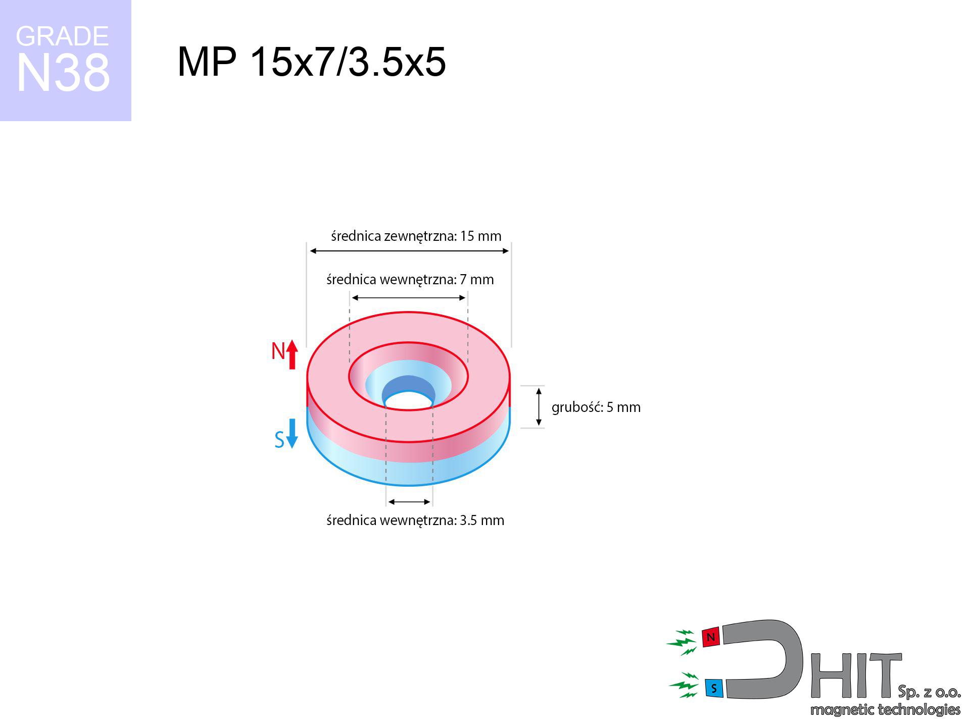
MP 15x7/3.5x5 / N38 - ring magnet
ring magnet
Catalog no 030390
GTIN/EAN: 5906301812302
- Diameter
- 15 mm [±0,1 mm]
- internal diameter Ø
- 7/3.5 mm [±0,1 mm]
- Height
- 5 mm [±0,1 mm]
- Weight
- 6.27 g
- Magnetization Direction
- ↑ axial
- Coating
- [NiCuNi] Nickel
3.44 zł with VAT / pcs + price for transport
2.80 zł net + 23% VAT / pcs
bulk discounts:
Need more?Engineering report for this magnet
Full PDF analysis: pull and shear force, effect of distance, temperature and plate thickness, safety distances and the demagnetization curve.
Give us a call
+48 22 499 98 98
alternatively let us know through
request form
the contact section.
Lifting power along with shape of magnets can be tested using our
magnetic mass calculator.
Order by 14:00 and we’ll ship today!
Technical of the product - MP 15x7/3.5x5 / N38 - ring magnet
Specification / characteristics - MP 15x7/3.5x5 / N38 - ring magnet
| properties | values |
|---|---|
| Cat. no. | 030390 |
| GTIN/EAN | 5906301812302 |
| Production/Distribution | Dhit sp. z o.o. |
| Country of origin | Poland / China / Germany |
| Customs code | 85059029 |
| Diameter | 15 mm [±0,1 mm] |
| internal diameter Ø | 7/3.5 mm [±0,1 mm] |
| Height | 5 mm [±0,1 mm] |
| Weight | 6.27 g |
| Magnetization Direction | ↑ axial |
| Load capacity ~ ? | 5.09 kg / 49.95 N |
| Magnetic Induction ~ ? | 343.70 mT / 3437 Gs |
| Coating | [NiCuNi] Nickel |
| Manufacturing Tolerance | ±0.1 mm |
Magnetic properties of material N38
| properties | values | units |
|---|---|---|
| remenance Br [min. - max.] ? | 12.2-12.6 | kGs |
| remenance Br [min. - max.] ? | 1220-1260 | mT |
| coercivity bHc ? | 10.8-11.5 | kOe |
| coercivity bHc ? | 860-915 | kA/m |
| actual internal force iHc | ≥ 12 | kOe |
| actual internal force iHc | ≥ 955 | kA/m |
| energy density [min. - max.] ? | 36-38 | BH max MGOe |
| energy density [min. - max.] ? | 287-303 | BH max KJ/m |
| max. temperature ? | ≤ 80 | °C |
Physical properties of sintered neodymium magnets Nd2Fe14B at 20°C
| properties | values | units |
|---|---|---|
| Vickers hardness | ≥550 | Hv |
| Density | ≥7.4 | g/cm3 |
| Curie Temperature TC | 312 - 380 | °C |
| Curie Temperature TF | 593 - 716 | °F |
| Specific resistance | 150 | μΩ⋅cm |
| Bending strength | 250 | MPa |
| Compressive strength | 1000~1100 | MPa |
| Thermal expansion parallel (∥) to orientation (M) | (3-4) x 10-6 | °C-1 |
| Thermal expansion perpendicular (⊥) to orientation (M) | -(1-3) x 10-6 | °C-1 |
| Young's modulus | 1.7 x 10⁴ | kg/mm² |
Technical modeling of the product - report
These information are the outcome of a engineering simulation. Results were calculated on models for the material Nd2Fe14B. Actual parameters might slightly differ. Treat these calculations as a reference point during assembly planning.
Table 1: Static pull force (pull vs distance) - characteristics
MP 15x7/3.5x5 / N38
| Distance (mm) | Induction (Gauss) / mT | Pull Force (kg/lbs/g/N) | Risk Status |
|---|---|---|---|
| 0 mm |
3054 Gs
305.4 mT
|
5.09 kg / 11.22 lbs
5090.0 g / 49.9 N
|
warning |
| 1 mm |
2736 Gs
273.6 mT
|
4.09 kg / 9.01 lbs
4085.7 g / 40.1 N
|
warning |
| 2 mm |
2372 Gs
237.2 mT
|
3.07 kg / 6.77 lbs
3069.9 g / 30.1 N
|
warning |
| 3 mm |
2007 Gs
200.7 mT
|
2.20 kg / 4.84 lbs
2197.4 g / 21.6 N
|
warning |
| 5 mm |
1377 Gs
137.7 mT
|
1.03 kg / 2.28 lbs
1034.5 g / 10.1 N
|
safe |
| 10 mm |
526 Gs
52.6 mT
|
0.15 kg / 0.33 lbs
151.3 g / 1.5 N
|
safe |
| 15 mm |
232 Gs
23.2 mT
|
0.03 kg / 0.06 lbs
29.3 g / 0.3 N
|
safe |
| 20 mm |
118 Gs
11.8 mT
|
0.01 kg / 0.02 lbs
7.6 g / 0.1 N
|
safe |
| 30 mm |
42 Gs
4.2 mT
|
0.00 kg / 0.00 lbs
0.9 g / 0.0 N
|
safe |
| 50 mm |
10 Gs
1.0 mT
|
0.00 kg / 0.00 lbs
0.1 g / 0.0 N
|
safe |
Table 2: Slippage capacity (vertical surface)
MP 15x7/3.5x5 / N38
| Distance (mm) | Friction coefficient | Pull Force (kg/lbs/g/N) |
|---|---|---|
| 0 mm | Stal (~0.2) |
1.02 kg / 2.24 lbs
1018.0 g / 10.0 N
|
| 1 mm | Stal (~0.2) |
0.82 kg / 1.80 lbs
818.0 g / 8.0 N
|
| 2 mm | Stal (~0.2) |
0.61 kg / 1.35 lbs
614.0 g / 6.0 N
|
| 3 mm | Stal (~0.2) |
0.44 kg / 0.97 lbs
440.0 g / 4.3 N
|
| 5 mm | Stal (~0.2) |
0.21 kg / 0.45 lbs
206.0 g / 2.0 N
|
| 10 mm | Stal (~0.2) |
0.03 kg / 0.07 lbs
30.0 g / 0.3 N
|
| 15 mm | Stal (~0.2) |
0.01 kg / 0.01 lbs
6.0 g / 0.1 N
|
| 20 mm | Stal (~0.2) |
0.00 kg / 0.00 lbs
2.0 g / 0.0 N
|
| 30 mm | Stal (~0.2) |
0.00 kg / 0.00 lbs
0.0 g / 0.0 N
|
| 50 mm | Stal (~0.2) |
0.00 kg / 0.00 lbs
0.0 g / 0.0 N
|
Table 3: Wall mounting (sliding) - behavior on slippery surfaces
MP 15x7/3.5x5 / N38
| Surface type | Friction coefficient / % Mocy | Max load (kg/lbs/g/N) |
|---|---|---|
| Raw steel |
µ = 0.3
30% Nominalnej Siły
|
1.53 kg / 3.37 lbs
1527.0 g / 15.0 N
|
| Painted steel (standard) |
µ = 0.2
20% Nominalnej Siły
|
1.02 kg / 2.24 lbs
1018.0 g / 10.0 N
|
| Oily/slippery steel |
µ = 0.1
10% Nominalnej Siły
|
0.51 kg / 1.12 lbs
509.0 g / 5.0 N
|
| Magnet with anti-slip rubber |
µ = 0.5
50% Nominalnej Siły
|
2.55 kg / 5.61 lbs
2545.0 g / 25.0 N
|
Table 4: Material efficiency (substrate influence) - power losses
MP 15x7/3.5x5 / N38
| Steel thickness (mm) | % power | Real pull force (kg/lbs/g/N) |
|---|---|---|
| 0.5 mm |
|
0.51 kg / 1.12 lbs
509.0 g / 5.0 N
|
| 1 mm |
|
1.27 kg / 2.81 lbs
1272.5 g / 12.5 N
|
| 2 mm |
|
2.55 kg / 5.61 lbs
2545.0 g / 25.0 N
|
| 3 mm |
|
3.82 kg / 8.42 lbs
3817.5 g / 37.4 N
|
| 5 mm |
|
5.09 kg / 11.22 lbs
5090.0 g / 49.9 N
|
| 10 mm |
|
5.09 kg / 11.22 lbs
5090.0 g / 49.9 N
|
| 11 mm |
|
5.09 kg / 11.22 lbs
5090.0 g / 49.9 N
|
| 12 mm |
|
5.09 kg / 11.22 lbs
5090.0 g / 49.9 N
|
Table 5: Working in heat (material behavior) - power drop
MP 15x7/3.5x5 / N38
| Ambient temp. (°C) | Power loss | Remaining pull (kg/lbs/g/N) | Status |
|---|---|---|---|
| 20 °C | 0.0% |
5.09 kg / 11.22 lbs
5090.0 g / 49.9 N
|
OK |
| 40 °C | -2.2% |
4.98 kg / 10.97 lbs
4978.0 g / 48.8 N
|
OK |
| 60 °C | -4.4% |
4.87 kg / 10.73 lbs
4866.0 g / 47.7 N
|
|
| 80 °C | -6.6% |
4.75 kg / 10.48 lbs
4754.1 g / 46.6 N
|
|
| 100 °C | -28.8% |
3.62 kg / 7.99 lbs
3624.1 g / 35.6 N
|
Table 6: Two magnets (attraction) - forces in the system
MP 15x7/3.5x5 / N38
| Gap (mm) | Attraction (kg/lbs) (N-S) | Lateral Force (kg/lbs/g/N) | Repulsion (kg/lbs) (N-N) |
|---|---|---|---|
| 0 mm |
8.17 kg / 18.00 lbs
4 643 Gs
|
1.22 kg / 2.70 lbs
1225 g / 12.0 N
|
N/A |
| 1 mm |
7.39 kg / 16.29 lbs
5 810 Gs
|
1.11 kg / 2.44 lbs
1108 g / 10.9 N
|
6.65 kg / 14.66 lbs
~0 Gs
|
| 2 mm |
6.55 kg / 14.45 lbs
5 472 Gs
|
0.98 kg / 2.17 lbs
983 g / 9.6 N
|
5.90 kg / 13.01 lbs
~0 Gs
|
| 3 mm |
5.72 kg / 12.62 lbs
5 113 Gs
|
0.86 kg / 1.89 lbs
858 g / 8.4 N
|
5.15 kg / 11.35 lbs
~0 Gs
|
| 5 mm |
4.19 kg / 9.23 lbs
4 374 Gs
|
0.63 kg / 1.38 lbs
628 g / 6.2 N
|
3.77 kg / 8.31 lbs
~0 Gs
|
| 10 mm |
1.66 kg / 3.66 lbs
2 753 Gs
|
0.25 kg / 0.55 lbs
249 g / 2.4 N
|
1.49 kg / 3.29 lbs
~0 Gs
|
| 20 mm |
0.24 kg / 0.54 lbs
1 053 Gs
|
0.04 kg / 0.08 lbs
36 g / 0.4 N
|
0.22 kg / 0.48 lbs
~0 Gs
|
| 50 mm |
0.00 kg / 0.01 lbs
134 Gs
|
0.00 kg / 0.00 lbs
1 g / 0.0 N
|
0.00 kg / 0.00 lbs
~0 Gs
|
| 60 mm |
0.00 kg / 0.00 lbs
83 Gs
|
0.00 kg / 0.00 lbs
0 g / 0.0 N
|
0.00 kg / 0.00 lbs
~0 Gs
|
| 70 mm |
0.00 kg / 0.00 lbs
55 Gs
|
0.00 kg / 0.00 lbs
0 g / 0.0 N
|
0.00 kg / 0.00 lbs
~0 Gs
|
| 80 mm |
0.00 kg / 0.00 lbs
38 Gs
|
0.00 kg / 0.00 lbs
0 g / 0.0 N
|
0.00 kg / 0.00 lbs
~0 Gs
|
| 90 mm |
0.00 kg / 0.00 lbs
27 Gs
|
0.00 kg / 0.00 lbs
0 g / 0.0 N
|
0.00 kg / 0.00 lbs
~0 Gs
|
| 100 mm |
0.00 kg / 0.00 lbs
20 Gs
|
0.00 kg / 0.00 lbs
0 g / 0.0 N
|
0.00 kg / 0.00 lbs
~0 Gs
|
Table 7: Protective zones (electronics) - warnings
MP 15x7/3.5x5 / N38
| Object / Device | Limit (Gauss) / mT | Safe distance |
|---|---|---|
| Pacemaker | 5 Gs (0.5 mT) | 6.5 cm |
| Hearing aid | 10 Gs (1.0 mT) | 5.5 cm |
| Timepiece | 20 Gs (2.0 mT) | 4.0 cm |
| Mobile device | 40 Gs (4.0 mT) | 3.5 cm |
| Remote | 50 Gs (5.0 mT) | 3.0 cm |
| Payment card | 400 Gs (40.0 mT) | 1.5 cm |
| HDD hard drive | 600 Gs (60.0 mT) | 1.0 cm |
Table 8: Impact energy (cracking risk) - warning
MP 15x7/3.5x5 / N38
| Start from (mm) | Speed (km/h) | Energy (J) | Predicted outcome |
|---|---|---|---|
| 10 mm |
25.60 km/h
(7.11 m/s)
|
0.16 J | |
| 30 mm |
25.98 km/h
(7.22 m/s)
|
0.16 J | |
| 50 mm |
25.98 km/h
(7.22 m/s)
|
0.16 J | |
| 100 mm |
25.98 km/h
(7.22 m/s)
|
0.16 J |
Table 9: Coating parameters (durability)
MP 15x7/3.5x5 / N38
| Technical parameter | Value / Description |
|---|---|
| Coating type | [NiCuNi] Nickel |
| Layer structure | Nickel - Copper - Nickel |
| Layer thickness | 10-20 µm |
| Salt spray test (SST) ? | 24 h |
| Recommended environment | Indoors only (dry) |
Table 10: Electrical data (Flux)
MP 15x7/3.5x5 / N38
| Parameter | Value | SI Unit / Description |
|---|---|---|
| Magnetic Flux | 4 791 Mx | 47.9 µWb |
| Pc Coefficient | 0.39 | Low (Flat) |
Table 11: Physics of underwater searching
MP 15x7/3.5x5 / N38
| Environment | Effective steel pull | Effect |
|---|---|---|
| Air (land) | 5.09 kg | Standard |
| Water (riverbed) |
5.83 kg
(+0.74 kg buoyancy gain)
|
+14.5% |
1. Vertical hold
*Note: On a vertical wall, the magnet retains only ~20% of its perpendicular strength.
2. Steel saturation
*Thin metal sheet (e.g. computer case) drastically limits the holding force.
3. Power loss vs temp
*For N38 grade, the critical limit is 80°C.
4. Demagnetization curve and operating point (B-H)
chart generated for the permeance coefficient Pc (Permeance Coefficient) = 0.39
The chart above illustrates the magnetic characteristics of the material within the second quadrant of the hysteresis loop. The solid red line represents the demagnetization curve (material potential), while the dashed blue line is the load line based on the magnet's geometry. The Pc (Permeance Coefficient), also known as the load line slope, is a dimensionless value that describes the relationship between the magnet's shape and its magnetic stability. The intersection of these two lines (the black dot) is the operating point — it determines the actual magnetic flux density generated by the magnet in this specific configuration. A higher Pc value means the magnet is more 'slender' (tall relative to its area), resulting in a higher operating point and better resistance to irreversible demagnetization caused by external fields or temperature. A value of 0.42 is relatively low (typical for flat magnets), meaning the operating point is closer to the 'knee' of the curve — caution is advised when operating at temperatures near the maximum limit to avoid strength loss.
Chemical composition
| iron (Fe) | 64% – 68% |
| neodymium (Nd) | 29% – 32% |
| boron (B) | 1.1% – 1.2% |
| dysprosium (Dy) | 0.5% – 2.0% |
| coating (Ni-Cu-Ni) | < 0.05% |
Sustainability
| recyclability (EoL) | 100% |
| recycled raw materials | ~10% (pre-cons) |
| carbon footprint | low / zredukowany |
| waste code (EWC) | 16 02 16 |
View more offers


![BM 510x180x70 [4x M8] - magnetic beam](https://cdn3.dhit.pl/graphics/products/bm-510x180x70-4x-m8-cem.jpg "BM 510x180x70 [4x M8] - magnetic beam")

Strengths as well as weaknesses of rare earth magnets.
Benefits
- Their power is durable, and after approximately 10 years it decreases only by ~1% (according to research),
- They do not lose their magnetic properties even under strong external field,
- A magnet with a smooth silver surface has an effective appearance,
- Neodymium magnets achieve maximum magnetic induction on a small surface, which increases force concentration,
- Through (adequate) combination of ingredients, they can achieve high thermal strength, allowing for operation at temperatures reaching 230°C and above...
- Thanks to the potential of flexible molding and customization to custom needs, NdFeB magnets can be created in a broad palette of shapes and sizes, which makes them more universal,
- Key role in innovative solutions – they are commonly used in hard drives, electric motors, medical devices, and modern systems.
- Compactness – despite small sizes they provide effective action, making them ideal for precision applications
Limitations
- They are prone to damage upon heavy impacts. To avoid cracks, it is worth securing magnets using a steel holder. Such protection not only shields the magnet but also improves its resistance to damage
- We warn that neodymium magnets can lose their power at high temperatures. To prevent this, we suggest our specialized [AH] magnets, which work effectively even at 230°C.
- When exposed to humidity, magnets usually rust. For applications outside, it is recommended to use protective magnets, such as magnets in rubber or plastics, which prevent oxidation and corrosion.
- Limited possibility of producing nuts in the magnet and complex shapes - preferred is casing - mounting mechanism.
- Potential hazard resulting from small fragments of magnets can be dangerous, if swallowed, which gains importance in the context of child safety. Furthermore, small elements of these magnets can complicate diagnosis medical when they are in the body.
- Due to complex production process, their price is higher than average,
Lifting parameters
Highest magnetic holding force – what contributes to it?
- on a block made of mild steel, optimally conducting the magnetic flux
- with a cross-section no less than 10 mm
- characterized by even structure
- without the slightest air gap between the magnet and steel
- for force acting at a right angle (in the magnet axis)
- in temp. approx. 20°C
Impact of factors on magnetic holding capacity in practice
- Gap between surfaces – every millimeter of distance (caused e.g. by veneer or unevenness) significantly weakens the magnet efficiency, often by half at just 0.5 mm.
- Force direction – note that the magnet holds strongest perpendicularly. Under shear forces, the holding force drops drastically, often to levels of 20-30% of the nominal value.
- Base massiveness – insufficiently thick steel does not accept the full field, causing part of the flux to be escaped into the air.
- Material type – ideal substrate is pure iron steel. Hardened steels may have worse magnetic properties.
- Base smoothness – the smoother and more polished the plate, the larger the contact zone and stronger the hold. Unevenness creates an air distance.
- Thermal conditions – neodymium magnets have a sensitivity to temperature. When it is hot they lose power, and at low temperatures they can be stronger (up to a certain limit).
Lifting capacity was determined by applying a steel plate with a smooth surface of optimal thickness (min. 20 mm), under perpendicular pulling force, in contrast under attempts to slide the magnet the load capacity is reduced by as much as 75%. Additionally, even a small distance between the magnet and the plate decreases the lifting capacity.
H&S for magnets
Mechanical processing
Machining of neodymium magnets carries a risk of fire hazard. Magnetic powder oxidizes rapidly with oxygen and is hard to extinguish.
Impact on smartphones
Note: neodymium magnets generate a field that confuses precision electronics. Keep a separation from your mobile, device, and navigation systems.
Electronic devices
Device Safety: Neodymium magnets can damage data carriers and sensitive devices (heart implants, hearing aids, timepieces).
Handling guide
Before use, check safety instructions. Sudden snapping can break the magnet or hurt your hand. Be predictive.
Do not overheat magnets
Watch the temperature. Heating the magnet above 80 degrees Celsius will permanently weaken its properties and strength.
Beware of splinters
Beware of splinters. Magnets can explode upon violent connection, ejecting shards into the air. Wear goggles.
Danger to pacemakers
Health Alert: Neodymium magnets can deactivate heart devices and defibrillators. Stay away if you have electronic implants.
Danger to the youngest
Strictly store magnets away from children. Ingestion danger is high, and the consequences of magnets clamping inside the body are life-threatening.
Bodily injuries
Risk of injury: The attraction force is so great that it can cause hematomas, pinching, and broken bones. Protective gloves are recommended.
Allergic reactions
Medical facts indicate that the nickel plating (the usual finish) is a common allergen. For allergy sufferers, prevent direct skin contact or opt for versions in plastic housing.
Tabela kosztu i czasu dostawy
Płatność przed wysyłką:

GLS kurier
Przesyłka będzie u Ciebie za 2-3 dni
14.99 ZŁ

InPost Paczkomaty 24/7
Przesyłka będzie u Ciebie za 1-2 dni
12.30 ZŁ
Płatność przy odbiorze (pobranie):
GLS kurier
Przesyłka będzie u Ciebie za 1-2 dni
23.00 ZŁ
Rate the product
Your rating