
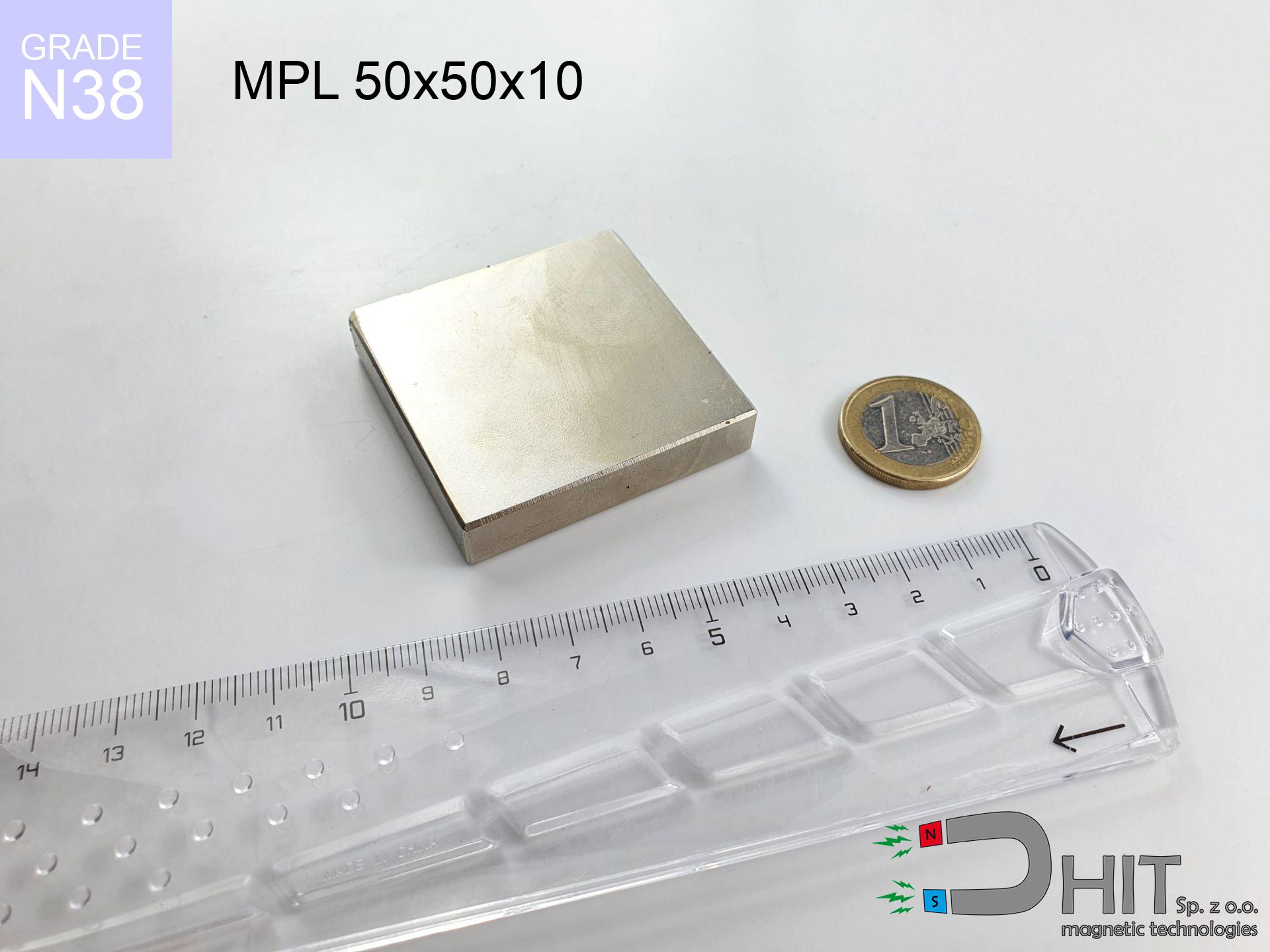
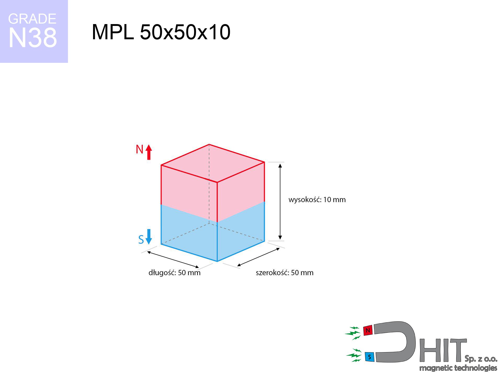
MPL 50x50x10 / N38 - lamellar magnet
lamellar magnet
Catalog no 020167
GTIN/EAN: 5906301811732
length
50 mm [±0,1 mm]
Width
50 mm [±0,1 mm]
Height
10 mm [±0,1 mm]
Weight
187.5 g
Magnetization Direction
↑ axial
Load capacity
33.73 kg / 330.92 N
Magnetic Induction
209.75 mT / 2097 Gs
Coating
[NiCuNi] Nickel
42.88 ZŁ with VAT / pcs + price for transport
34.86 ZŁ net + 23% VAT / pcs
bulk discounts:
Need more?
Call us
+48 888 99 98 98
alternatively let us know by means of
form
our website.
Force and appearance of a neodymium magnet can be checked using our
modular calculator.
Orders submitted before 14:00 will be dispatched today!
Detailed specification - MPL 50x50x10 / N38 - lamellar magnet
Specification / characteristics - MPL 50x50x10 / N38 - lamellar magnet
| properties | values |
|---|---|
| Cat. no. | 020167 |
| GTIN/EAN | 5906301811732 |
| Production/Distribution | Dhit sp. z o.o. |
| Country of origin | Poland / China / Germany |
| Customs code | 85059029 |
| length | 50 mm [±0,1 mm] |
| Width | 50 mm [±0,1 mm] |
| Height | 10 mm [±0,1 mm] |
| Weight | 187.5 g |
| Magnetization Direction | ↑ axial |
| Load capacity ~ ? | 33.73 kg / 330.92 N |
| Magnetic Induction ~ ? | 209.75 mT / 2097 Gs |
| Coating | [NiCuNi] Nickel |
| Manufacturing Tolerance | ±0.1 mm |
Magnetic properties of material N38
| properties | values | units |
|---|---|---|
| remenance Br [min. - max.] ? | 12.2-12.6 | kGs |
| remenance Br [min. - max.] ? | 1220-1260 | mT |
| coercivity bHc ? | 10.8-11.5 | kOe |
| coercivity bHc ? | 860-915 | kA/m |
| actual internal force iHc | ≥ 12 | kOe |
| actual internal force iHc | ≥ 955 | kA/m |
| energy density [min. - max.] ? | 36-38 | BH max MGOe |
| energy density [min. - max.] ? | 287-303 | BH max KJ/m |
| max. temperature ? | ≤ 80 | °C |
Physical properties of sintered neodymium magnets Nd2Fe14B at 20°C
| properties | values | units |
|---|---|---|
| Vickers hardness | ≥550 | Hv |
| Density | ≥7.4 | g/cm3 |
| Curie Temperature TC | 312 - 380 | °C |
| Curie Temperature TF | 593 - 716 | °F |
| Specific resistance | 150 | μΩ⋅cm |
| Bending strength | 250 | MPa |
| Compressive strength | 1000~1100 | MPa |
| Thermal expansion parallel (∥) to orientation (M) | (3-4) x 10-6 | °C-1 |
| Thermal expansion perpendicular (⊥) to orientation (M) | -(1-3) x 10-6 | °C-1 |
| Young's modulus | 1.7 x 10⁴ | kg/mm² |
Technical modeling of the product - data
Presented information are the result of a physical analysis. Results rely on algorithms for the class Nd2Fe14B. Operational performance might slightly differ. Use these calculations as a preliminary roadmap for designers.
Table 1: Static force (pull vs gap) - power drop
MPL 50x50x10 / N38
| Distance (mm) | Induction (Gauss) / mT | Pull Force (kg/lbs/g/N) | Risk Status |
|---|---|---|---|
| 0 mm |
2097 Gs
209.7 mT
|
33.73 kg / 74.36 pounds
33730.0 g / 330.9 N
|
critical level |
| 1 mm |
2056 Gs
205.6 mT
|
32.43 kg / 71.50 pounds
32430.0 g / 318.1 N
|
critical level |
| 2 mm |
2009 Gs
200.9 mT
|
30.96 kg / 68.27 pounds
30964.6 g / 303.8 N
|
critical level |
| 3 mm |
1957 Gs
195.7 mT
|
29.38 kg / 64.77 pounds
29380.4 g / 288.2 N
|
critical level |
| 5 mm |
1841 Gs
184.1 mT
|
25.99 kg / 57.30 pounds
25992.3 g / 255.0 N
|
critical level |
| 10 mm |
1514 Gs
151.4 mT
|
17.58 kg / 38.75 pounds
17577.6 g / 172.4 N
|
critical level |
| 15 mm |
1194 Gs
119.4 mT
|
10.93 kg / 24.10 pounds
10931.8 g / 107.2 N
|
critical level |
| 20 mm |
922 Gs
92.2 mT
|
6.51 kg / 14.36 pounds
6512.2 g / 63.9 N
|
strong |
| 30 mm |
543 Gs
54.3 mT
|
2.26 kg / 4.98 pounds
2260.0 g / 22.2 N
|
strong |
| 50 mm |
209 Gs
20.9 mT
|
0.33 kg / 0.74 pounds
334.1 g / 3.3 N
|
weak grip |
Table 2: Shear force (wall)
MPL 50x50x10 / N38
| Distance (mm) | Friction coefficient | Pull Force (kg/lbs/g/N) |
|---|---|---|
| 0 mm | Stal (~0.2) |
6.75 kg / 14.87 pounds
6746.0 g / 66.2 N
|
| 1 mm | Stal (~0.2) |
6.49 kg / 14.30 pounds
6486.0 g / 63.6 N
|
| 2 mm | Stal (~0.2) |
6.19 kg / 13.65 pounds
6192.0 g / 60.7 N
|
| 3 mm | Stal (~0.2) |
5.88 kg / 12.95 pounds
5876.0 g / 57.6 N
|
| 5 mm | Stal (~0.2) |
5.20 kg / 11.46 pounds
5198.0 g / 51.0 N
|
| 10 mm | Stal (~0.2) |
3.52 kg / 7.75 pounds
3516.0 g / 34.5 N
|
| 15 mm | Stal (~0.2) |
2.19 kg / 4.82 pounds
2186.0 g / 21.4 N
|
| 20 mm | Stal (~0.2) |
1.30 kg / 2.87 pounds
1302.0 g / 12.8 N
|
| 30 mm | Stal (~0.2) |
0.45 kg / 1.00 pounds
452.0 g / 4.4 N
|
| 50 mm | Stal (~0.2) |
0.07 kg / 0.15 pounds
66.0 g / 0.6 N
|
Table 3: Wall mounting (shearing) - behavior on slippery surfaces
MPL 50x50x10 / N38
| Surface type | Friction coefficient / % Mocy | Max load (kg/lbs/g/N) |
|---|---|---|
| Raw steel |
µ = 0.3
30% Nominalnej Siły
|
10.12 kg / 22.31 pounds
10119.0 g / 99.3 N
|
| Painted steel (standard) |
µ = 0.2
20% Nominalnej Siły
|
6.75 kg / 14.87 pounds
6746.0 g / 66.2 N
|
| Oily/slippery steel |
µ = 0.1
10% Nominalnej Siły
|
3.37 kg / 7.44 pounds
3373.0 g / 33.1 N
|
| Magnet with anti-slip rubber |
µ = 0.5
50% Nominalnej Siły
|
16.87 kg / 37.18 pounds
16865.0 g / 165.4 N
|
Table 4: Material efficiency (substrate influence) - sheet metal selection
MPL 50x50x10 / N38
| Steel thickness (mm) | % power | Real pull force (kg/lbs/g/N) |
|---|---|---|
| 0.5 mm |
|
1.69 kg / 3.72 pounds
1686.5 g / 16.5 N
|
| 1 mm |
|
4.22 kg / 9.30 pounds
4216.3 g / 41.4 N
|
| 2 mm |
|
8.43 kg / 18.59 pounds
8432.5 g / 82.7 N
|
| 3 mm |
|
12.65 kg / 27.89 pounds
12648.8 g / 124.1 N
|
| 5 mm |
|
21.08 kg / 46.48 pounds
21081.2 g / 206.8 N
|
| 10 mm |
|
33.73 kg / 74.36 pounds
33730.0 g / 330.9 N
|
| 11 mm |
|
33.73 kg / 74.36 pounds
33730.0 g / 330.9 N
|
| 12 mm |
|
33.73 kg / 74.36 pounds
33730.0 g / 330.9 N
|
Table 5: Working in heat (stability) - power drop
MPL 50x50x10 / N38
| Ambient temp. (°C) | Power loss | Remaining pull (kg/lbs/g/N) | Status |
|---|---|---|---|
| 20 °C | 0.0% |
33.73 kg / 74.36 pounds
33730.0 g / 330.9 N
|
OK |
| 40 °C | -2.2% |
32.99 kg / 72.73 pounds
32987.9 g / 323.6 N
|
OK |
| 60 °C | -4.4% |
32.25 kg / 71.09 pounds
32245.9 g / 316.3 N
|
|
| 80 °C | -6.6% |
31.50 kg / 69.45 pounds
31503.8 g / 309.1 N
|
|
| 100 °C | -28.8% |
24.02 kg / 52.95 pounds
24015.8 g / 235.6 N
|
Table 6: Magnet-Magnet interaction (repulsion) - field collision
MPL 50x50x10 / N38
| Gap (mm) | Attraction (kg/lbs) (N-S) | Sliding Force (kg/lbs/g/N) | Repulsion (kg/lbs) (N-N) |
|---|---|---|---|
| 0 mm |
67.80 kg / 149.46 pounds
3 611 Gs
|
10.17 kg / 22.42 pounds
10169 g / 99.8 N
|
N/A |
| 1 mm |
66.54 kg / 146.70 pounds
4 156 Gs
|
9.98 kg / 22.01 pounds
9982 g / 97.9 N
|
59.89 kg / 132.03 pounds
~0 Gs
|
| 2 mm |
65.18 kg / 143.70 pounds
4 113 Gs
|
9.78 kg / 21.56 pounds
9777 g / 95.9 N
|
58.66 kg / 129.33 pounds
~0 Gs
|
| 3 mm |
63.74 kg / 140.53 pounds
4 067 Gs
|
9.56 kg / 21.08 pounds
9562 g / 93.8 N
|
57.37 kg / 126.48 pounds
~0 Gs
|
| 5 mm |
60.67 kg / 133.75 pounds
3 968 Gs
|
9.10 kg / 20.06 pounds
9101 g / 89.3 N
|
54.60 kg / 120.38 pounds
~0 Gs
|
| 10 mm |
52.24 kg / 115.18 pounds
3 682 Gs
|
7.84 kg / 17.28 pounds
7836 g / 76.9 N
|
47.02 kg / 103.66 pounds
~0 Gs
|
| 20 mm |
35.33 kg / 77.89 pounds
3 028 Gs
|
5.30 kg / 11.68 pounds
5299 g / 52.0 N
|
31.80 kg / 70.10 pounds
~0 Gs
|
| 50 mm |
7.69 kg / 16.96 pounds
1 413 Gs
|
1.15 kg / 2.54 pounds
1154 g / 11.3 N
|
6.92 kg / 15.26 pounds
~0 Gs
|
| 60 mm |
4.54 kg / 10.01 pounds
1 086 Gs
|
0.68 kg / 1.50 pounds
681 g / 6.7 N
|
4.09 kg / 9.01 pounds
~0 Gs
|
| 70 mm |
2.72 kg / 6.01 pounds
841 Gs
|
0.41 kg / 0.90 pounds
409 g / 4.0 N
|
2.45 kg / 5.41 pounds
~0 Gs
|
| 80 mm |
1.67 kg / 3.68 pounds
658 Gs
|
0.25 kg / 0.55 pounds
250 g / 2.5 N
|
1.50 kg / 3.31 pounds
~0 Gs
|
| 90 mm |
1.05 kg / 2.31 pounds
521 Gs
|
0.16 kg / 0.35 pounds
157 g / 1.5 N
|
0.94 kg / 2.08 pounds
~0 Gs
|
| 100 mm |
0.67 kg / 1.48 pounds
417 Gs
|
0.10 kg / 0.22 pounds
101 g / 1.0 N
|
0.60 kg / 1.33 pounds
~0 Gs
|
Table 7: Hazards (implants) - warnings
MPL 50x50x10 / N38
| Object / Device | Limit (Gauss) / mT | Safe distance |
|---|---|---|
| Pacemaker | 5 Gs (0.5 mT) | 21.0 cm |
| Hearing aid | 10 Gs (1.0 mT) | 16.5 cm |
| Mechanical watch | 20 Gs (2.0 mT) | 13.0 cm |
| Mobile device | 40 Gs (4.0 mT) | 10.0 cm |
| Remote | 50 Gs (5.0 mT) | 9.5 cm |
| Payment card | 400 Gs (40.0 mT) | 4.0 cm |
| HDD hard drive | 600 Gs (60.0 mT) | 3.0 cm |
Table 8: Collisions (cracking risk) - warning
MPL 50x50x10 / N38
| Start from (mm) | Speed (km/h) | Energy (J) | Predicted outcome |
|---|---|---|---|
| 10 mm |
17.38 km/h
(4.83 m/s)
|
2.19 J | |
| 30 mm |
24.39 km/h
(6.78 m/s)
|
4.30 J | |
| 50 mm |
30.43 km/h
(8.45 m/s)
|
6.70 J | |
| 100 mm |
42.78 km/h
(11.88 m/s)
|
13.24 J |
Table 9: Anti-corrosion coating durability
MPL 50x50x10 / N38
| Technical parameter | Value / Description |
|---|---|
| Coating type | [NiCuNi] Nickel |
| Layer structure | Nickel - Copper - Nickel |
| Layer thickness | 10-20 µm |
| Salt spray test (SST) ? | 24 h |
| Recommended environment | Indoors only (dry) |
Table 10: Electrical data (Flux)
MPL 50x50x10 / N38
| Parameter | Value | SI Unit / Description |
|---|---|---|
| Magnetic Flux | 61 501 Mx | 615.0 µWb |
| Pc Coefficient | 0.26 | Low (Flat) |
Table 11: Underwater work (magnet fishing)
MPL 50x50x10 / N38
| Environment | Effective steel pull | Effect |
|---|---|---|
| Air (land) | 33.73 kg | Standard |
| Water (riverbed) |
38.62 kg
(+4.89 kg buoyancy gain)
|
+14.5% |
1. Vertical hold
*Note: On a vertical wall, the magnet retains merely ~20% of its perpendicular strength.
2. Efficiency vs thickness
*Thin steel (e.g. 0.5mm PC case) severely limits the holding force.
3. Temperature resistance
*For N38 material, the critical limit is 80°C.
4. Demagnetization curve and operating point (B-H)
chart generated for the permeance coefficient Pc (Permeance Coefficient) = 0.26
The chart above illustrates the magnetic characteristics of the material within the second quadrant of the hysteresis loop. The solid red line represents the demagnetization curve (material potential), while the dashed blue line is the load line based on the magnet's geometry. The Pc (Permeance Coefficient), also known as the load line slope, is a dimensionless value that describes the relationship between the magnet's shape and its magnetic stability. The intersection of these two lines (the black dot) is the operating point — it determines the actual magnetic flux density generated by the magnet in this specific configuration. A higher Pc value means the magnet is more 'slender' (tall relative to its area), resulting in a higher operating point and better resistance to irreversible demagnetization caused by external fields or temperature. A value of 0.42 is relatively low (typical for flat magnets), meaning the operating point is closer to the 'knee' of the curve — caution is advised when operating at temperatures near the maximum limit to avoid strength loss.
Material specification
| iron (Fe) | 64% – 68% |
| neodymium (Nd) | 29% – 32% |
| boron (B) | 1.1% – 1.2% |
| dysprosium (Dy) | 0.5% – 2.0% |
| coating (Ni-Cu-Ni) | < 0.05% |
Ecology and recycling (GPSR)
| recyclability (EoL) | 100% |
| recycled raw materials | ~10% (pre-cons) |
| carbon footprint | low / zredukowany |
| waste code (EWC) | 16 02 16 |
Other proposals


![HH 42x8.8 [M6] / N38 - through hole magnetic holder](https://cdn3.dhit.pl/graphics/products/hh-42x8.8-m6-hin.jpg "HH 42x8.8 [M6] / N38 - through hole magnetic holder")
![UMGZ 25x17x8 [M5] GZ / N38 - magnetic holder external thread](https://cdn3.dhit.pl/graphics/products/um-25x17x8-m5-gz-keb.jpg "UMGZ 25x17x8 [M5] GZ / N38 - magnetic holder external thread")
Pros and cons of neodymium magnets.
Pros
- They virtually do not lose power, because even after ten years the decline in efficiency is only ~1% (in laboratory conditions),
- Magnets very well protect themselves against demagnetization caused by external fields,
- By using a lustrous coating of nickel, the element acquires an aesthetic look,
- Magnetic induction on the working layer of the magnet turns out to be strong,
- Due to their durability and thermal resistance, neodymium magnets are capable of operate (depending on the form) even at high temperatures reaching 230°C or more...
- Possibility of exact creating as well as adjusting to precise applications,
- Wide application in electronics industry – they find application in magnetic memories, electric motors, advanced medical instruments, also complex engineering applications.
- Thanks to concentrated force, small magnets offer high operating force, in miniature format,
Cons
- Brittleness is one of their disadvantages. Upon intense impact they can break. We advise keeping them in a steel housing, which not only secures them against impacts but also raises their durability
- Neodymium magnets demagnetize when exposed to high temperatures. After reaching 80°C, many of them experience permanent drop of power (a factor is the shape as well as dimensions of the magnet). We offer magnets specially adapted to work at temperatures up to 230°C marked [AH], which are extremely resistant to heat
- Magnets exposed to a humid environment can corrode. Therefore during using outdoors, we suggest using waterproof magnets made of rubber, plastic or other material protecting against moisture
- We recommend cover - magnetic mount, due to difficulties in creating nuts inside the magnet and complicated shapes.
- Health risk resulting from small fragments of magnets can be dangerous, if swallowed, which becomes key in the context of child safety. It is also worth noting that tiny parts of these devices are able to disrupt the diagnostic process medical when they are in the body.
- High unit price – neodymium magnets are more expensive than other types of magnets (e.g. ferrite), which can limit application in large quantities
Pull force analysis
Maximum lifting force for a neodymium magnet – what it depends on?
- using a plate made of mild steel, acting as a ideal flux conductor
- possessing a thickness of min. 10 mm to ensure full flux closure
- with a plane perfectly flat
- with total lack of distance (without impurities)
- for force applied at a right angle (in the magnet axis)
- in neutral thermal conditions
Determinants of lifting force in real conditions
- Air gap (between the magnet and the metal), as even a tiny distance (e.g. 0.5 mm) results in a decrease in force by up to 50% (this also applies to paint, rust or debris).
- Force direction – catalog parameter refers to detachment vertically. When applying parallel force, the magnet exhibits significantly lower power (typically approx. 20-30% of nominal force).
- Steel thickness – insufficiently thick plate does not close the flux, causing part of the flux to be escaped to the other side.
- Plate material – low-carbon steel attracts best. Alloy steels reduce magnetic properties and lifting capacity.
- Surface quality – the more even the plate, the better the adhesion and higher the lifting capacity. Roughness acts like micro-gaps.
- Heat – NdFeB sinters have a sensitivity to temperature. At higher temperatures they are weaker, and in frost gain strength (up to a certain limit).
Lifting capacity testing was conducted on a smooth plate of optimal thickness, under perpendicular forces, however under parallel forces the load capacity is reduced by as much as fivefold. In addition, even a small distance between the magnet’s surface and the plate lowers the load capacity.
Safety rules for work with neodymium magnets
Magnetic interference
A strong magnetic field interferes with the functioning of magnetometers in smartphones and GPS navigation. Keep magnets near a smartphone to avoid damaging the sensors.
Implant safety
Warning for patients: Powerful magnets disrupt medical devices. Maintain minimum 30 cm distance or ask another person to work with the magnets.
Nickel coating and allergies
Allergy Notice: The nickel-copper-nickel coating contains nickel. If an allergic reaction happens, cease working with magnets and use protective gear.
Serious injuries
Watch your fingers. Two large magnets will join immediately with a force of several hundred kilograms, crushing everything in their path. Exercise extreme caution!
Adults only
Only for adults. Tiny parts can be swallowed, causing serious injuries. Store out of reach of kids and pets.
Shattering risk
Watch out for shards. Magnets can fracture upon violent connection, launching shards into the air. We recommend safety glasses.
Permanent damage
Keep cool. Neodymium magnets are susceptible to heat. If you require resistance above 80°C, look for special high-temperature series (H, SH, UH).
Dust explosion hazard
Combustion risk: Rare earth powder is highly flammable. Do not process magnets without safety gear as this may cause fire.
Caution required
Before starting, read the rules. Uncontrolled attraction can break the magnet or hurt your hand. Think ahead.
Data carriers
Data protection: Strong magnets can damage data carriers and delicate electronics (pacemakers, medical aids, timepieces).
Tabela kosztu i czasu dostawy
Płatność przed wysyłką:

GLS kurier
Przesyłka będzie u Ciebie za 2-3 dni
14.99 ZŁ

InPost Paczkomaty 24/7
Przesyłka będzie u Ciebie za 1-2 dni
12.30 ZŁ
Płatność przy odbiorze (pobranie):
GLS kurier
Przesyłka będzie u Ciebie za 1-2 dni
23.00 ZŁ
Rate the product
Your rating