

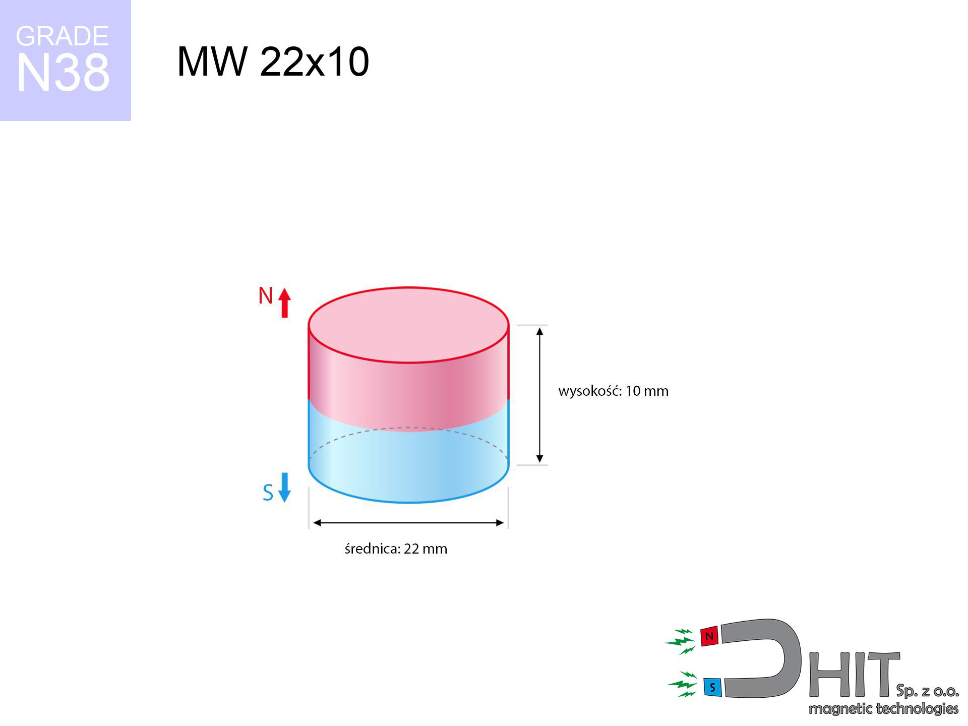
MW 22x10 / N38 - cylindrical magnet
cylindrical magnet
Catalog no 010046
GTIN/EAN: 5906301810452
Diameter Ø
22 mm [±0,1 mm]
Height
10 mm [±0,1 mm]
Weight
28.51 g
Magnetization Direction
↑ axial
Load capacity
14.75 kg / 144.65 N
Magnetic Induction
416.85 mT / 4168 Gs
Coating
[NiCuNi] Nickel
11.30 ZŁ with VAT / pcs + price for transport
9.19 ZŁ net + 23% VAT / pcs
bulk discounts:
Need more?
Call us now
+48 888 99 98 98
or contact us by means of
request form
our website.
Weight along with appearance of neodymium magnets can be calculated using our
force calculator.
Same-day processing for orders placed before 14:00.
Technical of the product - MW 22x10 / N38 - cylindrical magnet
Specification / characteristics - MW 22x10 / N38 - cylindrical magnet
| properties | values |
|---|---|
| Cat. no. | 010046 |
| GTIN/EAN | 5906301810452 |
| Production/Distribution | Dhit sp. z o.o. |
| Country of origin | Poland / China / Germany |
| Customs code | 85059029 |
| Diameter Ø | 22 mm [±0,1 mm] |
| Height | 10 mm [±0,1 mm] |
| Weight | 28.51 g |
| Magnetization Direction | ↑ axial |
| Load capacity ~ ? | 14.75 kg / 144.65 N |
| Magnetic Induction ~ ? | 416.85 mT / 4168 Gs |
| Coating | [NiCuNi] Nickel |
| Manufacturing Tolerance | ±0.1 mm |
Magnetic properties of material N38
| properties | values | units |
|---|---|---|
| remenance Br [min. - max.] ? | 12.2-12.6 | kGs |
| remenance Br [min. - max.] ? | 1220-1260 | mT |
| coercivity bHc ? | 10.8-11.5 | kOe |
| coercivity bHc ? | 860-915 | kA/m |
| actual internal force iHc | ≥ 12 | kOe |
| actual internal force iHc | ≥ 955 | kA/m |
| energy density [min. - max.] ? | 36-38 | BH max MGOe |
| energy density [min. - max.] ? | 287-303 | BH max KJ/m |
| max. temperature ? | ≤ 80 | °C |
Physical properties of sintered neodymium magnets Nd2Fe14B at 20°C
| properties | values | units |
|---|---|---|
| Vickers hardness | ≥550 | Hv |
| Density | ≥7.4 | g/cm3 |
| Curie Temperature TC | 312 - 380 | °C |
| Curie Temperature TF | 593 - 716 | °F |
| Specific resistance | 150 | μΩ⋅cm |
| Bending strength | 250 | MPa |
| Compressive strength | 1000~1100 | MPa |
| Thermal expansion parallel (∥) to orientation (M) | (3-4) x 10-6 | °C-1 |
| Thermal expansion perpendicular (⊥) to orientation (M) | -(1-3) x 10-6 | °C-1 |
| Young's modulus | 1.7 x 10⁴ | kg/mm² |
Engineering simulation of the assembly - report
The following information represent the outcome of a physical simulation. Results are based on models for the material Nd2Fe14B. Actual parameters might slightly differ. Use these data as a preliminary roadmap for designers.
Table 1: Static force (force vs distance) - power drop
MW 22x10 / N38
| Distance (mm) | Induction (Gauss) / mT | Pull Force (kg/lbs/g/N) | Risk Status |
|---|---|---|---|
| 0 mm |
4167 Gs
416.7 mT
|
14.75 kg / 32.52 pounds
14750.0 g / 144.7 N
|
crushing |
| 1 mm |
3823 Gs
382.3 mT
|
12.41 kg / 27.36 pounds
12412.2 g / 121.8 N
|
crushing |
| 2 mm |
3461 Gs
346.1 mT
|
10.18 kg / 22.43 pounds
10175.8 g / 99.8 N
|
crushing |
| 3 mm |
3102 Gs
310.2 mT
|
8.17 kg / 18.01 pounds
8171.3 g / 80.2 N
|
medium risk |
| 5 mm |
2434 Gs
243.4 mT
|
5.03 kg / 11.09 pounds
5032.6 g / 49.4 N
|
medium risk |
| 10 mm |
1262 Gs
126.2 mT
|
1.35 kg / 2.98 pounds
1352.7 g / 13.3 N
|
low risk |
| 15 mm |
675 Gs
67.5 mT
|
0.39 kg / 0.85 pounds
387.3 g / 3.8 N
|
low risk |
| 20 mm |
388 Gs
38.8 mT
|
0.13 kg / 0.28 pounds
128.2 g / 1.3 N
|
low risk |
| 30 mm |
157 Gs
15.7 mT
|
0.02 kg / 0.05 pounds
20.9 g / 0.2 N
|
low risk |
| 50 mm |
43 Gs
4.3 mT
|
0.00 kg / 0.00 pounds
1.6 g / 0.0 N
|
low risk |
Table 2: Sliding force (wall)
MW 22x10 / N38
| Distance (mm) | Friction coefficient | Pull Force (kg/lbs/g/N) |
|---|---|---|
| 0 mm | Stal (~0.2) |
2.95 kg / 6.50 pounds
2950.0 g / 28.9 N
|
| 1 mm | Stal (~0.2) |
2.48 kg / 5.47 pounds
2482.0 g / 24.3 N
|
| 2 mm | Stal (~0.2) |
2.04 kg / 4.49 pounds
2036.0 g / 20.0 N
|
| 3 mm | Stal (~0.2) |
1.63 kg / 3.60 pounds
1634.0 g / 16.0 N
|
| 5 mm | Stal (~0.2) |
1.01 kg / 2.22 pounds
1006.0 g / 9.9 N
|
| 10 mm | Stal (~0.2) |
0.27 kg / 0.60 pounds
270.0 g / 2.6 N
|
| 15 mm | Stal (~0.2) |
0.08 kg / 0.17 pounds
78.0 g / 0.8 N
|
| 20 mm | Stal (~0.2) |
0.03 kg / 0.06 pounds
26.0 g / 0.3 N
|
| 30 mm | Stal (~0.2) |
0.00 kg / 0.01 pounds
4.0 g / 0.0 N
|
| 50 mm | Stal (~0.2) |
0.00 kg / 0.00 pounds
0.0 g / 0.0 N
|
Table 3: Vertical assembly (sliding) - vertical pull
MW 22x10 / N38
| Surface type | Friction coefficient / % Mocy | Max load (kg/lbs/g/N) |
|---|---|---|
| Raw steel |
µ = 0.3
30% Nominalnej Siły
|
4.43 kg / 9.76 pounds
4425.0 g / 43.4 N
|
| Painted steel (standard) |
µ = 0.2
20% Nominalnej Siły
|
2.95 kg / 6.50 pounds
2950.0 g / 28.9 N
|
| Oily/slippery steel |
µ = 0.1
10% Nominalnej Siły
|
1.48 kg / 3.25 pounds
1475.0 g / 14.5 N
|
| Magnet with anti-slip rubber |
µ = 0.5
50% Nominalnej Siły
|
7.38 kg / 16.26 pounds
7375.0 g / 72.3 N
|
Table 4: Material efficiency (substrate influence) - power losses
MW 22x10 / N38
| Steel thickness (mm) | % power | Real pull force (kg/lbs/g/N) |
|---|---|---|
| 0.5 mm |
|
0.74 kg / 1.63 pounds
737.5 g / 7.2 N
|
| 1 mm |
|
1.84 kg / 4.06 pounds
1843.8 g / 18.1 N
|
| 2 mm |
|
3.69 kg / 8.13 pounds
3687.5 g / 36.2 N
|
| 3 mm |
|
5.53 kg / 12.19 pounds
5531.3 g / 54.3 N
|
| 5 mm |
|
9.22 kg / 20.32 pounds
9218.8 g / 90.4 N
|
| 10 mm |
|
14.75 kg / 32.52 pounds
14750.0 g / 144.7 N
|
| 11 mm |
|
14.75 kg / 32.52 pounds
14750.0 g / 144.7 N
|
| 12 mm |
|
14.75 kg / 32.52 pounds
14750.0 g / 144.7 N
|
Table 5: Working in heat (material behavior) - power drop
MW 22x10 / N38
| Ambient temp. (°C) | Power loss | Remaining pull (kg/lbs/g/N) | Status |
|---|---|---|---|
| 20 °C | 0.0% |
14.75 kg / 32.52 pounds
14750.0 g / 144.7 N
|
OK |
| 40 °C | -2.2% |
14.43 kg / 31.80 pounds
14425.5 g / 141.5 N
|
OK |
| 60 °C | -4.4% |
14.10 kg / 31.09 pounds
14101.0 g / 138.3 N
|
|
| 80 °C | -6.6% |
13.78 kg / 30.37 pounds
13776.5 g / 135.1 N
|
|
| 100 °C | -28.8% |
10.50 kg / 23.15 pounds
10502.0 g / 103.0 N
|
Table 6: Two magnets (attraction) - field range
MW 22x10 / N38
| Gap (mm) | Attraction (kg/lbs) (N-S) | Shear Strength (kg/lbs/g/N) | Repulsion (kg/lbs) (N-N) |
|---|---|---|---|
| 0 mm |
40.70 kg / 89.72 pounds
5 428 Gs
|
6.10 kg / 13.46 pounds
6105 g / 59.9 N
|
N/A |
| 1 mm |
37.49 kg / 82.64 pounds
7 999 Gs
|
5.62 kg / 12.40 pounds
5623 g / 55.2 N
|
33.74 kg / 74.38 pounds
~0 Gs
|
| 2 mm |
34.25 kg / 75.50 pounds
7 645 Gs
|
5.14 kg / 11.33 pounds
5137 g / 50.4 N
|
30.82 kg / 67.95 pounds
~0 Gs
|
| 3 mm |
31.10 kg / 68.56 pounds
7 285 Gs
|
4.66 kg / 10.28 pounds
4664 g / 45.8 N
|
27.99 kg / 61.70 pounds
~0 Gs
|
| 5 mm |
25.22 kg / 55.60 pounds
6 561 Gs
|
3.78 kg / 8.34 pounds
3783 g / 37.1 N
|
22.70 kg / 50.04 pounds
~0 Gs
|
| 10 mm |
13.89 kg / 30.61 pounds
4 868 Gs
|
2.08 kg / 4.59 pounds
2083 g / 20.4 N
|
12.50 kg / 27.55 pounds
~0 Gs
|
| 20 mm |
3.73 kg / 8.23 pounds
2 524 Gs
|
0.56 kg / 1.23 pounds
560 g / 5.5 N
|
3.36 kg / 7.41 pounds
~0 Gs
|
| 50 mm |
0.13 kg / 0.30 pounds
480 Gs
|
0.02 kg / 0.04 pounds
20 g / 0.2 N
|
0.12 kg / 0.27 pounds
~0 Gs
|
| 60 mm |
0.06 kg / 0.13 pounds
314 Gs
|
0.01 kg / 0.02 pounds
9 g / 0.1 N
|
0.05 kg / 0.11 pounds
~0 Gs
|
| 70 mm |
0.03 kg / 0.06 pounds
216 Gs
|
0.00 kg / 0.01 pounds
4 g / 0.0 N
|
0.02 kg / 0.05 pounds
~0 Gs
|
| 80 mm |
0.01 kg / 0.03 pounds
154 Gs
|
0.00 kg / 0.00 pounds
2 g / 0.0 N
|
0.01 kg / 0.03 pounds
~0 Gs
|
| 90 mm |
0.01 kg / 0.02 pounds
114 Gs
|
0.00 kg / 0.00 pounds
1 g / 0.0 N
|
0.00 kg / 0.00 pounds
~0 Gs
|
| 100 mm |
0.00 kg / 0.01 pounds
86 Gs
|
0.00 kg / 0.00 pounds
1 g / 0.0 N
|
0.00 kg / 0.00 pounds
~0 Gs
|
Table 7: Hazards (electronics) - warnings
MW 22x10 / N38
| Object / Device | Limit (Gauss) / mT | Safe distance |
|---|---|---|
| Pacemaker | 5 Gs (0.5 mT) | 11.0 cm |
| Hearing aid | 10 Gs (1.0 mT) | 9.0 cm |
| Mechanical watch | 20 Gs (2.0 mT) | 7.0 cm |
| Mobile device | 40 Gs (4.0 mT) | 5.5 cm |
| Remote | 50 Gs (5.0 mT) | 5.0 cm |
| Payment card | 400 Gs (40.0 mT) | 2.0 cm |
| HDD hard drive | 600 Gs (60.0 mT) | 2.0 cm |
Table 8: Impact energy (cracking risk) - collision effects
MW 22x10 / N38
| Start from (mm) | Speed (km/h) | Energy (J) | Predicted outcome |
|---|---|---|---|
| 10 mm |
24.22 km/h
(6.73 m/s)
|
0.65 J | |
| 30 mm |
39.77 km/h
(11.05 m/s)
|
1.74 J | |
| 50 mm |
51.30 km/h
(14.25 m/s)
|
2.89 J | |
| 100 mm |
72.54 km/h
(20.15 m/s)
|
5.79 J |
Table 9: Corrosion resistance
MW 22x10 / N38
| Technical parameter | Value / Description |
|---|---|
| Coating type | [NiCuNi] Nickel |
| Layer structure | Nickel - Copper - Nickel |
| Layer thickness | 10-20 µm |
| Salt spray test (SST) ? | 24 h |
| Recommended environment | Indoors only (dry) |
Table 10: Construction data (Pc)
MW 22x10 / N38
| Parameter | Value | SI Unit / Description |
|---|---|---|
| Magnetic Flux | 16 172 Mx | 161.7 µWb |
| Pc Coefficient | 0.55 | Low (Flat) |
Table 11: Physics of underwater searching
MW 22x10 / N38
| Environment | Effective steel pull | Effect |
|---|---|---|
| Air (land) | 14.75 kg | Standard |
| Water (riverbed) |
16.89 kg
(+2.14 kg buoyancy gain)
|
+14.5% |
1. Wall mount (shear)
*Caution: On a vertical surface, the magnet holds only ~20% of its perpendicular strength.
2. Steel thickness impact
*Thin steel (e.g. 0.5mm PC case) significantly limits the holding force.
3. Heat tolerance
*For N38 material, the max working temp is 80°C.
4. Demagnetization curve and operating point (B-H)
chart generated for the permeance coefficient Pc (Permeance Coefficient) = 0.55
This simulation demonstrates the magnetic stability of the selected magnet under specific geometric conditions. The solid red line represents the demagnetization curve (material potential), while the dashed blue line is the load line based on the magnet's geometry. The Pc (Permeance Coefficient), also known as the load line slope, is a dimensionless value that describes the relationship between the magnet's shape and its magnetic stability. The intersection of these two lines (the black dot) is the operating point — it determines the actual magnetic flux density generated by the magnet in this specific configuration. A higher Pc value means the magnet is more 'slender' (tall relative to its area), resulting in a higher operating point and better resistance to irreversible demagnetization caused by external fields or temperature. A value of 0.42 is relatively low (typical for flat magnets), meaning the operating point is closer to the 'knee' of the curve — caution is advised when operating at temperatures near the maximum limit to avoid strength loss.
Elemental analysis
| iron (Fe) | 64% – 68% |
| neodymium (Nd) | 29% – 32% |
| boron (B) | 1.1% – 1.2% |
| dysprosium (Dy) | 0.5% – 2.0% |
| coating (Ni-Cu-Ni) | < 0.05% |
Environmental data
| recyclability (EoL) | 100% |
| recycled raw materials | ~10% (pre-cons) |
| carbon footprint | low / zredukowany |
| waste code (EWC) | 16 02 16 |
Other products

![UMGZ 42x20x9 [M8] GZ / N38 - magnetic holder external thread](https://cdn3.dhit.pl/graphics/products/um-42x20x9-m8-gz-fof.jpg "UMGZ 42x20x9 [M8] GZ / N38 - magnetic holder external thread")


Advantages and disadvantages of Nd2Fe14B magnets.
Pros
- They do not lose strength, even over around ten years – the decrease in strength is only ~1% (according to tests),
- They are extremely resistant to demagnetization induced by external disturbances,
- The use of an shiny coating of noble metals (nickel, gold, silver) causes the element to have aesthetics,
- Magnets have huge magnetic induction on the outer side,
- Due to their durability and thermal resistance, neodymium magnets can operate (depending on the form) even at high temperatures reaching 230°C or more...
- Possibility of accurate creating as well as adjusting to concrete conditions,
- Huge importance in electronics industry – they find application in magnetic memories, electromotive mechanisms, precision medical tools, also complex engineering applications.
- Compactness – despite small sizes they offer powerful magnetic field, making them ideal for precision applications
Limitations
- They are fragile upon too strong impacts. To avoid cracks, it is worth protecting magnets in special housings. Such protection not only protects the magnet but also increases its resistance to damage
- NdFeB magnets demagnetize when exposed to high temperatures. After reaching 80°C, many of them experience permanent weakening of power (a factor is the shape and dimensions of the magnet). We offer magnets specially adapted to work at temperatures up to 230°C marked [AH], which are very resistant to heat
- Due to the susceptibility of magnets to corrosion in a humid environment, we suggest using waterproof magnets made of rubber, plastic or other material resistant to moisture, in case of application outdoors
- Due to limitations in realizing nuts and complicated forms in magnets, we propose using casing - magnetic mechanism.
- Possible danger to health – tiny shards of magnets can be dangerous, when accidentally swallowed, which is particularly important in the aspect of protecting the youngest. It is also worth noting that tiny parts of these devices are able to be problematic in diagnostics medical when they are in the body.
- Due to neodymium price, their price exceeds standard values,
Lifting parameters
Highest magnetic holding force – what it depends on?
- using a base made of high-permeability steel, acting as a circuit closing element
- with a thickness minimum 10 mm
- with a surface free of scratches
- under conditions of ideal adhesion (surface-to-surface)
- for force acting at a right angle (pull-off, not shear)
- at temperature room level
Key elements affecting lifting force
- Distance – the presence of any layer (paint, dirt, gap) acts as an insulator, which lowers power rapidly (even by 50% at 0.5 mm).
- Force direction – note that the magnet holds strongest perpendicularly. Under sliding down, the capacity drops significantly, often to levels of 20-30% of the nominal value.
- Wall thickness – the thinner the sheet, the weaker the hold. Part of the magnetic field penetrates through instead of converting into lifting capacity.
- Plate material – mild steel attracts best. Alloy admixtures lower magnetic permeability and lifting capacity.
- Base smoothness – the more even the plate, the larger the contact zone and higher the lifting capacity. Roughness creates an air distance.
- Thermal conditions – NdFeB sinters have a sensitivity to temperature. When it is hot they lose power, and at low temperatures gain strength (up to a certain limit).
Lifting capacity testing was conducted on a smooth plate of suitable thickness, under a perpendicular pulling force, in contrast under shearing force the lifting capacity is smaller. Additionally, even a slight gap between the magnet’s surface and the plate reduces the holding force.
Warnings
Magnetic interference
A powerful magnetic field disrupts the functioning of magnetometers in smartphones and GPS navigation. Keep magnets close to a smartphone to avoid damaging the sensors.
Nickel allergy
Some people have a contact allergy to Ni, which is the standard coating for NdFeB magnets. Frequent touching can result in dermatitis. We suggest use safety gloves.
Fragile material
Neodymium magnets are sintered ceramics, which means they are fragile like glass. Impact of two magnets will cause them shattering into small pieces.
Heat sensitivity
Standard neodymium magnets (grade N) undergo demagnetization when the temperature exceeds 80°C. The loss of strength is permanent.
Implant safety
For implant holders: Powerful magnets affect electronics. Maintain minimum 30 cm distance or ask another person to work with the magnets.
Safe operation
Handle magnets consciously. Their powerful strength can shock even professionals. Stay alert and respect their force.
Do not give to children
Adult use only. Small elements can be swallowed, causing intestinal necrosis. Keep out of reach of kids and pets.
Mechanical processing
Fire warning: Neodymium dust is highly flammable. Do not process magnets without safety gear as this risks ignition.
Hand protection
Big blocks can smash fingers instantly. Under no circumstances put your hand betwixt two strong magnets.
Keep away from computers
Intense magnetic fields can corrupt files on credit cards, HDDs, and storage devices. Maintain a gap of min. 10 cm.
Tabela kosztu i czasu dostawy
Płatność przed wysyłką:

GLS kurier
Przesyłka będzie u Ciebie za 2-3 dni
14.99 ZŁ

InPost Paczkomaty 24/7
Przesyłka będzie u Ciebie za 1-2 dni
12.30 ZŁ
Płatność przy odbiorze (pobranie):
GLS kurier
Przesyłka będzie u Ciebie za 1-2 dni
23.00 ZŁ
Rate the product
Your rating