

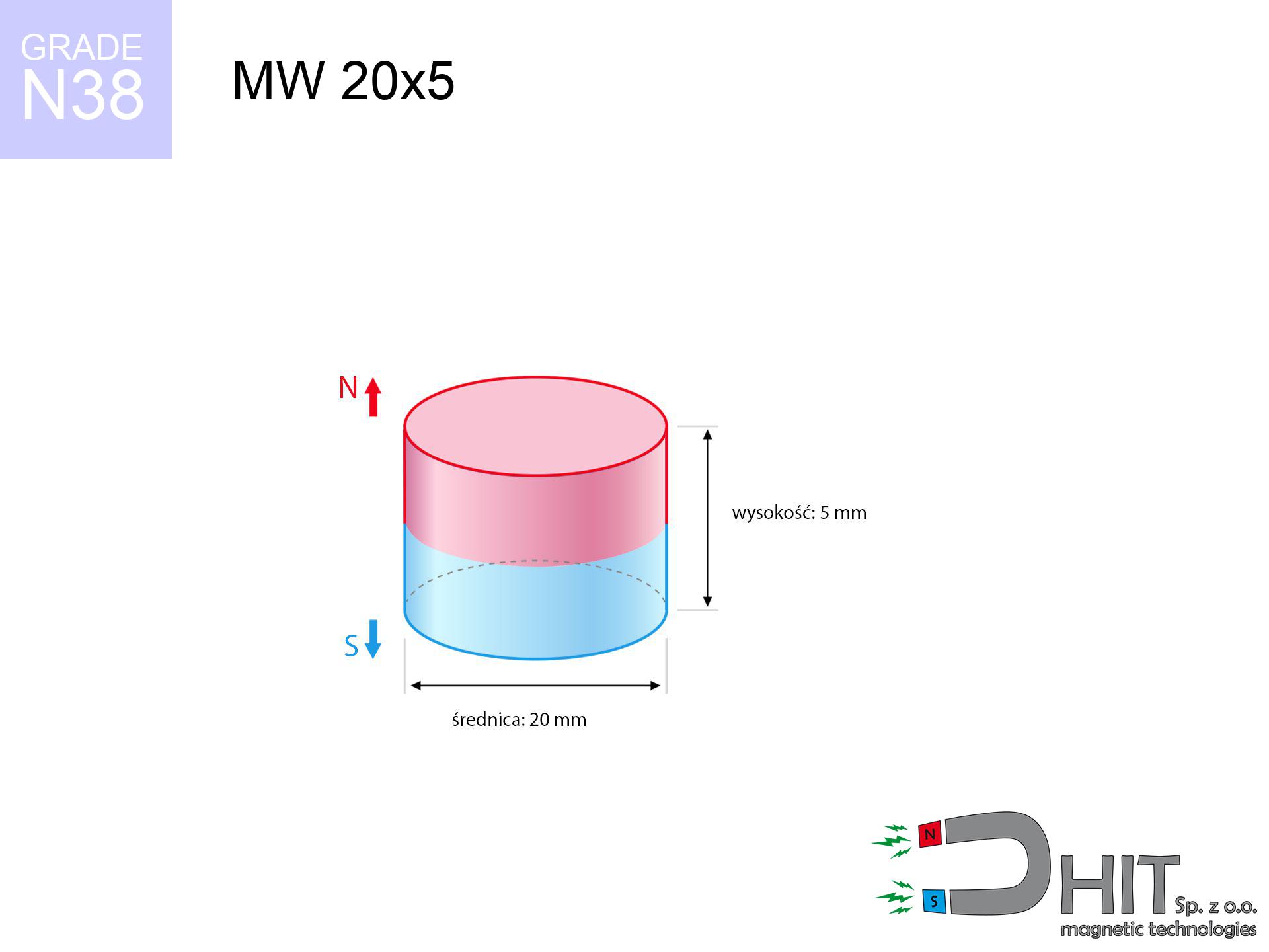
MW 20x5 / N38 - cylindrical magnet
cylindrical magnet
Catalog no 010044
GTIN/EAN: 5906301810438
- Diameter Ø
- 20 mm [±0,1 mm]
- Height
- 5 mm [±0,1 mm]
- Weight
- 11.78 g
- Magnetization Direction
- ↑ axial
- Coating
- [NiCuNi] Nickel
5.56 zł with VAT / pcs + price for transport
4.52 zł net + 23% VAT / pcs
bulk discounts:
Need more?Engineering report for this magnet
Full PDF analysis: pull and shear force, effect of distance, temperature and plate thickness, safety distances and the demagnetization curve.
Pick up the phone and ask
+48 22 499 98 98
if you prefer send us a note via
contact form
through our site.
Lifting power as well as form of a magnet can be analyzed on our
online calculation tool.
Orders submitted before 14:00 will be dispatched today!
Technical data - MW 20x5 / N38 - cylindrical magnet
Specification / characteristics - MW 20x5 / N38 - cylindrical magnet
| properties | values |
|---|---|
| Cat. no. | 010044 |
| GTIN/EAN | 5906301810438 |
| Production/Distribution | Dhit sp. z o.o. |
| Country of origin | Poland / China / Germany |
| Customs code | 85059029 |
| Diameter Ø | 20 mm [±0,1 mm] |
| Height | 5 mm [±0,1 mm] |
| Weight | 11.78 g |
| Magnetization Direction | ↑ axial |
| Load capacity ~ ? | 6.93 kg / 67.95 N |
| Magnetic Induction ~ ? | 277.16 mT / 2772 Gs |
| Coating | [NiCuNi] Nickel |
| Manufacturing Tolerance | ±0.1 mm |
Magnetic properties of material N38
| properties | values | units |
|---|---|---|
| remenance Br [min. - max.] ? | 12.2-12.6 | kGs |
| remenance Br [min. - max.] ? | 1220-1260 | mT |
| coercivity bHc ? | 10.8-11.5 | kOe |
| coercivity bHc ? | 860-915 | kA/m |
| actual internal force iHc | ≥ 12 | kOe |
| actual internal force iHc | ≥ 955 | kA/m |
| energy density [min. - max.] ? | 36-38 | BH max MGOe |
| energy density [min. - max.] ? | 287-303 | BH max KJ/m |
| max. temperature ? | ≤ 80 | °C |
Physical properties of sintered neodymium magnets Nd2Fe14B at 20°C
| properties | values | units |
|---|---|---|
| Vickers hardness | ≥550 | Hv |
| Density | ≥7.4 | g/cm3 |
| Curie Temperature TC | 312 - 380 | °C |
| Curie Temperature TF | 593 - 716 | °F |
| Specific resistance | 150 | μΩ⋅cm |
| Bending strength | 250 | MPa |
| Compressive strength | 1000~1100 | MPa |
| Thermal expansion parallel (∥) to orientation (M) | (3-4) x 10-6 | °C-1 |
| Thermal expansion perpendicular (⊥) to orientation (M) | -(1-3) x 10-6 | °C-1 |
| Young's modulus | 1.7 x 10⁴ | kg/mm² |
Technical simulation of the assembly - technical parameters
These information constitute the outcome of a physical analysis. Results were calculated on models for the material Nd2Fe14B. Real-world parameters may differ. Use these data as a reference point during assembly planning.
Table 1: Static pull force (force vs distance) - power drop
MW 20x5 / N38
| Distance (mm) | Induction (Gauss) / mT | Pull Force (kg/lbs/g/N) | Risk Status |
|---|---|---|---|
| 0 mm |
2771 Gs
277.1 mT
|
6.93 kg / 15.28 lbs
6930.0 g / 68.0 N
|
warning |
| 1 mm |
2573 Gs
257.3 mT
|
5.97 kg / 13.17 lbs
5975.0 g / 58.6 N
|
warning |
| 2 mm |
2340 Gs
234.0 mT
|
4.94 kg / 10.89 lbs
4940.1 g / 48.5 N
|
warning |
| 3 mm |
2092 Gs
209.2 mT
|
3.95 kg / 8.70 lbs
3948.3 g / 38.7 N
|
warning |
| 5 mm |
1611 Gs
161.1 mT
|
2.34 kg / 5.17 lbs
2343.4 g / 23.0 N
|
warning |
| 10 mm |
775 Gs
77.5 mT
|
0.54 kg / 1.19 lbs
541.6 g / 5.3 N
|
safe |
| 15 mm |
387 Gs
38.7 mT
|
0.13 kg / 0.30 lbs
135.0 g / 1.3 N
|
safe |
| 20 mm |
211 Gs
21.1 mT
|
0.04 kg / 0.09 lbs
40.2 g / 0.4 N
|
safe |
| 30 mm |
80 Gs
8.0 mT
|
0.01 kg / 0.01 lbs
5.7 g / 0.1 N
|
safe |
| 50 mm |
20 Gs
2.0 mT
|
0.00 kg / 0.00 lbs
0.4 g / 0.0 N
|
safe |
Table 2: Vertical capacity (vertical surface)
MW 20x5 / N38
| Distance (mm) | Friction coefficient | Pull Force (kg/lbs/g/N) |
|---|---|---|
| 0 mm | Stal (~0.2) |
1.39 kg / 3.06 lbs
1386.0 g / 13.6 N
|
| 1 mm | Stal (~0.2) |
1.19 kg / 2.63 lbs
1194.0 g / 11.7 N
|
| 2 mm | Stal (~0.2) |
0.99 kg / 2.18 lbs
988.0 g / 9.7 N
|
| 3 mm | Stal (~0.2) |
0.79 kg / 1.74 lbs
790.0 g / 7.7 N
|
| 5 mm | Stal (~0.2) |
0.47 kg / 1.03 lbs
468.0 g / 4.6 N
|
| 10 mm | Stal (~0.2) |
0.11 kg / 0.24 lbs
108.0 g / 1.1 N
|
| 15 mm | Stal (~0.2) |
0.03 kg / 0.06 lbs
26.0 g / 0.3 N
|
| 20 mm | Stal (~0.2) |
0.01 kg / 0.02 lbs
8.0 g / 0.1 N
|
| 30 mm | Stal (~0.2) |
0.00 kg / 0.00 lbs
2.0 g / 0.0 N
|
| 50 mm | Stal (~0.2) |
0.00 kg / 0.00 lbs
0.0 g / 0.0 N
|
Table 3: Vertical assembly (shearing) - vertical pull
MW 20x5 / N38
| Surface type | Friction coefficient / % Mocy | Max load (kg/lbs/g/N) |
|---|---|---|
| Raw steel |
µ = 0.3
30% Nominalnej Siły
|
2.08 kg / 4.58 lbs
2079.0 g / 20.4 N
|
| Painted steel (standard) |
µ = 0.2
20% Nominalnej Siły
|
1.39 kg / 3.06 lbs
1386.0 g / 13.6 N
|
| Oily/slippery steel |
µ = 0.1
10% Nominalnej Siły
|
0.69 kg / 1.53 lbs
693.0 g / 6.8 N
|
| Magnet with anti-slip rubber |
µ = 0.5
50% Nominalnej Siły
|
3.47 kg / 7.64 lbs
3465.0 g / 34.0 N
|
Table 4: Material efficiency (substrate influence) - sheet metal selection
MW 20x5 / N38
| Steel thickness (mm) | % power | Real pull force (kg/lbs/g/N) |
|---|---|---|
| 0.5 mm |
|
0.69 kg / 1.53 lbs
693.0 g / 6.8 N
|
| 1 mm |
|
1.73 kg / 3.82 lbs
1732.5 g / 17.0 N
|
| 2 mm |
|
3.47 kg / 7.64 lbs
3465.0 g / 34.0 N
|
| 3 mm |
|
5.20 kg / 11.46 lbs
5197.5 g / 51.0 N
|
| 5 mm |
|
6.93 kg / 15.28 lbs
6930.0 g / 68.0 N
|
| 10 mm |
|
6.93 kg / 15.28 lbs
6930.0 g / 68.0 N
|
| 11 mm |
|
6.93 kg / 15.28 lbs
6930.0 g / 68.0 N
|
| 12 mm |
|
6.93 kg / 15.28 lbs
6930.0 g / 68.0 N
|
Table 5: Thermal stability (material behavior) - thermal limit
MW 20x5 / N38
| Ambient temp. (°C) | Power loss | Remaining pull (kg/lbs/g/N) | Status |
|---|---|---|---|
| 20 °C | 0.0% |
6.93 kg / 15.28 lbs
6930.0 g / 68.0 N
|
OK |
| 40 °C | -2.2% |
6.78 kg / 14.94 lbs
6777.5 g / 66.5 N
|
OK |
| 60 °C | -4.4% |
6.63 kg / 14.61 lbs
6625.1 g / 65.0 N
|
|
| 80 °C | -6.6% |
6.47 kg / 14.27 lbs
6472.6 g / 63.5 N
|
|
| 100 °C | -28.8% |
4.93 kg / 10.88 lbs
4934.2 g / 48.4 N
|
Table 6: Magnet-Magnet interaction (attraction) - forces in the system
MW 20x5 / N38
| Gap (mm) | Attraction (kg/lbs) (N-S) | Sliding Force (kg/lbs/g/N) | Repulsion (kg/lbs) (N-N) |
|---|---|---|---|
| 0 mm |
14.87 kg / 32.79 lbs
4 380 Gs
|
2.23 kg / 4.92 lbs
2231 g / 21.9 N
|
N/A |
| 1 mm |
13.89 kg / 30.63 lbs
5 357 Gs
|
2.08 kg / 4.59 lbs
2084 g / 20.4 N
|
12.50 kg / 27.57 lbs
~0 Gs
|
| 2 mm |
12.82 kg / 28.27 lbs
5 146 Gs
|
1.92 kg / 4.24 lbs
1923 g / 18.9 N
|
11.54 kg / 25.44 lbs
~0 Gs
|
| 3 mm |
11.71 kg / 25.82 lbs
4 918 Gs
|
1.76 kg / 3.87 lbs
1757 g / 17.2 N
|
10.54 kg / 23.24 lbs
~0 Gs
|
| 5 mm |
9.51 kg / 20.97 lbs
4 433 Gs
|
1.43 kg / 3.15 lbs
1427 g / 14.0 N
|
8.56 kg / 18.88 lbs
~0 Gs
|
| 10 mm |
5.03 kg / 11.09 lbs
3 223 Gs
|
0.75 kg / 1.66 lbs
754 g / 7.4 N
|
4.53 kg / 9.98 lbs
~0 Gs
|
| 20 mm |
1.16 kg / 2.56 lbs
1 549 Gs
|
0.17 kg / 0.38 lbs
174 g / 1.7 N
|
1.05 kg / 2.31 lbs
~0 Gs
|
| 50 mm |
0.03 kg / 0.07 lbs
251 Gs
|
0.00 kg / 0.01 lbs
5 g / 0.0 N
|
0.03 kg / 0.06 lbs
~0 Gs
|
| 60 mm |
0.01 kg / 0.03 lbs
159 Gs
|
0.00 kg / 0.00 lbs
2 g / 0.0 N
|
0.01 kg / 0.02 lbs
~0 Gs
|
| 70 mm |
0.01 kg / 0.01 lbs
107 Gs
|
0.00 kg / 0.00 lbs
1 g / 0.0 N
|
0.00 kg / 0.00 lbs
~0 Gs
|
| 80 mm |
0.00 kg / 0.01 lbs
75 Gs
|
0.00 kg / 0.00 lbs
0 g / 0.0 N
|
0.00 kg / 0.00 lbs
~0 Gs
|
| 90 mm |
0.00 kg / 0.00 lbs
54 Gs
|
0.00 kg / 0.00 lbs
0 g / 0.0 N
|
0.00 kg / 0.00 lbs
~0 Gs
|
| 100 mm |
0.00 kg / 0.00 lbs
41 Gs
|
0.00 kg / 0.00 lbs
0 g / 0.0 N
|
0.00 kg / 0.00 lbs
~0 Gs
|
Table 7: Hazards (implants) - warnings
MW 20x5 / N38
| Object / Device | Limit (Gauss) / mT | Safe distance |
|---|---|---|
| Pacemaker | 5 Gs (0.5 mT) | 8.5 cm |
| Hearing aid | 10 Gs (1.0 mT) | 6.5 cm |
| Mechanical watch | 20 Gs (2.0 mT) | 5.5 cm |
| Phone / Smartphone | 40 Gs (4.0 mT) | 4.0 cm |
| Remote | 50 Gs (5.0 mT) | 4.0 cm |
| Payment card | 400 Gs (40.0 mT) | 1.5 cm |
| HDD hard drive | 600 Gs (60.0 mT) | 1.5 cm |
Table 8: Collisions (cracking risk) - collision effects
MW 20x5 / N38
| Start from (mm) | Speed (km/h) | Energy (J) | Predicted outcome |
|---|---|---|---|
| 10 mm |
24.91 km/h
(6.92 m/s)
|
0.28 J | |
| 30 mm |
25.76 km/h
(7.16 m/s)
|
0.30 J | |
| 50 mm |
25.78 km/h
(7.16 m/s)
|
0.30 J | |
| 100 mm |
25.78 km/h
(7.16 m/s)
|
0.30 J |
Table 9: Surface protection spec
MW 20x5 / N38
| Technical parameter | Value / Description |
|---|---|
| Coating type | [NiCuNi] Nickel |
| Layer structure | Nickel - Copper - Nickel |
| Layer thickness | 10-20 µm |
| Salt spray test (SST) ? | 24 h |
| Recommended environment | Indoors only (dry) |
Table 10: Electrical data (Flux)
MW 20x5 / N38
| Parameter | Value | SI Unit / Description |
|---|---|---|
| Magnetic Flux | 9 675 Mx | 96.7 µWb |
| Pc Coefficient | 0.35 | Low (Flat) |
Table 11: Hydrostatics and buoyancy
MW 20x5 / N38
| Environment | Effective steel pull | Effect |
|---|---|---|
| Air (land) | 6.93 kg | Standard |
| Water (riverbed) |
7.93 kg
(+1.00 kg buoyancy gain)
|
+14.5% |
1. Vertical hold
*Warning: On a vertical wall, the magnet holds merely ~20% of its max power.
2. Steel saturation
*Thin metal sheet (e.g. 0.5mm PC case) significantly limits the holding force.
3. Temperature resistance
*For standard magnets, the max working temp is 80°C.
4. Demagnetization curve and operating point (B-H)
chart generated for the permeance coefficient Pc (Permeance Coefficient) = 0.35
This simulation demonstrates the magnetic stability of the selected magnet under specific geometric conditions. The solid red line represents the demagnetization curve (material potential), while the dashed blue line is the load line based on the magnet's geometry. The Pc (Permeance Coefficient), also known as the load line slope, is a dimensionless value that describes the relationship between the magnet's shape and its magnetic stability. The intersection of these two lines (the black dot) is the operating point — it determines the actual magnetic flux density generated by the magnet in this specific configuration. A higher Pc value means the magnet is more 'slender' (tall relative to its area), resulting in a higher operating point and better resistance to irreversible demagnetization caused by external fields or temperature. A value of 0.42 is relatively low (typical for flat magnets), meaning the operating point is closer to the 'knee' of the curve — caution is advised when operating at temperatures near the maximum limit to avoid strength loss.
Elemental analysis
| iron (Fe) | 64% – 68% |
| neodymium (Nd) | 29% – 32% |
| boron (B) | 1.1% – 1.2% |
| dysprosium (Dy) | 0.5% – 2.0% |
| coating (Ni-Cu-Ni) | < 0.05% |
Sustainability
| recyclability (EoL) | 100% |
| recycled raw materials | ~10% (pre-cons) |
| carbon footprint | low / zredukowany |
| waste code (EWC) | 16 02 16 |
Other proposals

![UMH 60x15x69 [M8] / N38 - magnetic holder with hook](https://cdn3.dhit.pl/graphics/products/umh-60x15x69-m8-nij.jpg "UMH 60x15x69 [M8] / N38 - magnetic holder with hook")


Pros as well as cons of rare earth magnets.
Pros
- Their strength remains stable, and after around 10 years it decreases only by ~1% (theoretically),
- They possess excellent resistance to magnetic field loss as a result of external magnetic sources,
- By covering with a lustrous layer of nickel, the element gains an elegant look,
- They are known for high magnetic induction at the operating surface, making them more effective,
- Neodymium magnets are characterized by extremely high magnetic induction on the magnet surface and can function (depending on the shape) even at a temperature of 230°C or more...
- Considering the ability of precise shaping and adaptation to specialized projects, neodymium magnets can be modeled in a wide range of geometric configurations, which makes them more universal,
- Versatile presence in high-tech industry – they are utilized in HDD drives, brushless drives, medical equipment, as well as other advanced devices.
- Compactness – despite small sizes they offer powerful magnetic field, making them ideal for precision applications
Cons
- They are prone to damage upon too strong impacts. To avoid cracks, it is worth protecting magnets in special housings. Such protection not only shields the magnet but also increases its resistance to damage
- Neodymium magnets demagnetize when exposed to high temperatures. After reaching 80°C, many of them experience permanent weakening of power (a factor is the shape as well as dimensions of the magnet). We offer magnets specially adapted to work at temperatures up to 230°C marked [AH], which are extremely resistant to heat
- Due to the susceptibility of magnets to corrosion in a humid environment, we advise using waterproof magnets made of rubber, plastic or other material resistant to moisture, in case of application outdoors
- Due to limitations in creating threads and complicated forms in magnets, we recommend using cover - magnetic mount.
- Health risk resulting from small fragments of magnets can be dangerous, if swallowed, which becomes key in the context of child health protection. Additionally, tiny parts of these magnets are able to be problematic in diagnostics medical after entering the body.
- Higher cost of purchase is one of the disadvantages compared to ceramic magnets, especially in budget applications
Lifting parameters
Maximum lifting force for a neodymium magnet – what contributes to it?
- using a base made of high-permeability steel, functioning as a magnetic yoke
- whose transverse dimension is min. 10 mm
- characterized by smoothness
- under conditions of no distance (surface-to-surface)
- under axial force vector (90-degree angle)
- at standard ambient temperature
Practical lifting capacity: influencing factors
- Gap between magnet and steel – even a fraction of a millimeter of separation (caused e.g. by veneer or unevenness) significantly weakens the pulling force, often by half at just 0.5 mm.
- Pull-off angle – remember that the magnet holds strongest perpendicularly. Under shear forces, the capacity drops drastically, often to levels of 20-30% of the nominal value.
- Base massiveness – too thin plate does not close the flux, causing part of the flux to be escaped to the other side.
- Material type – ideal substrate is pure iron steel. Cast iron may have worse magnetic properties.
- Base smoothness – the smoother and more polished the plate, the larger the contact zone and stronger the hold. Roughness creates an air distance.
- Operating temperature – NdFeB sinters have a sensitivity to temperature. At higher temperatures they lose power, and in frost they can be stronger (up to a certain limit).
Holding force was tested on a smooth steel plate of 20 mm thickness, when a perpendicular force was applied, however under attempts to slide the magnet the load capacity is reduced by as much as 5 times. Moreover, even a slight gap between the magnet and the plate lowers the holding force.
Precautions when working with NdFeB magnets
Allergic reactions
Certain individuals suffer from a hypersensitivity to Ni, which is the typical protective layer for NdFeB magnets. Frequent touching can result in dermatitis. It is best to use safety gloves.
Caution required
Handle magnets with awareness. Their huge power can shock even experienced users. Stay alert and respect their force.
Risk of cracking
Neodymium magnets are sintered ceramics, meaning they are prone to chipping. Clashing of two magnets leads to them breaking into small pieces.
This is not a toy
Always keep magnets away from children. Choking hazard is high, and the consequences of magnets clamping inside the body are fatal.
Keep away from computers
Intense magnetic fields can destroy records on credit cards, hard drives, and storage devices. Stay away of min. 10 cm.
Pinching danger
Watch your fingers. Two powerful magnets will snap together instantly with a force of several hundred kilograms, destroying anything in their path. Be careful!
Warning for heart patients
Individuals with a pacemaker must maintain an absolute distance from magnets. The magnetism can stop the functioning of the life-saving device.
GPS and phone interference
Note: rare earth magnets generate a field that interferes with precision electronics. Maintain a safe distance from your mobile, tablet, and navigation systems.
Maximum temperature
Regular neodymium magnets (N-type) lose power when the temperature goes above 80°C. This process is irreversible.
Mechanical processing
Machining of NdFeB material carries a risk of fire risk. Neodymium dust oxidizes rapidly with oxygen and is difficult to extinguish.
Tabela kosztu i czasu dostawy
Płatność przed wysyłką:

GLS kurier
Przesyłka będzie u Ciebie za 2-3 dni
14.99 ZŁ

InPost Paczkomaty 24/7
Przesyłka będzie u Ciebie za 1-2 dni
12.30 ZŁ
Płatność przy odbiorze (pobranie):
GLS kurier
Przesyłka będzie u Ciebie za 1-2 dni
23.00 ZŁ
Rate the product
Your rating