
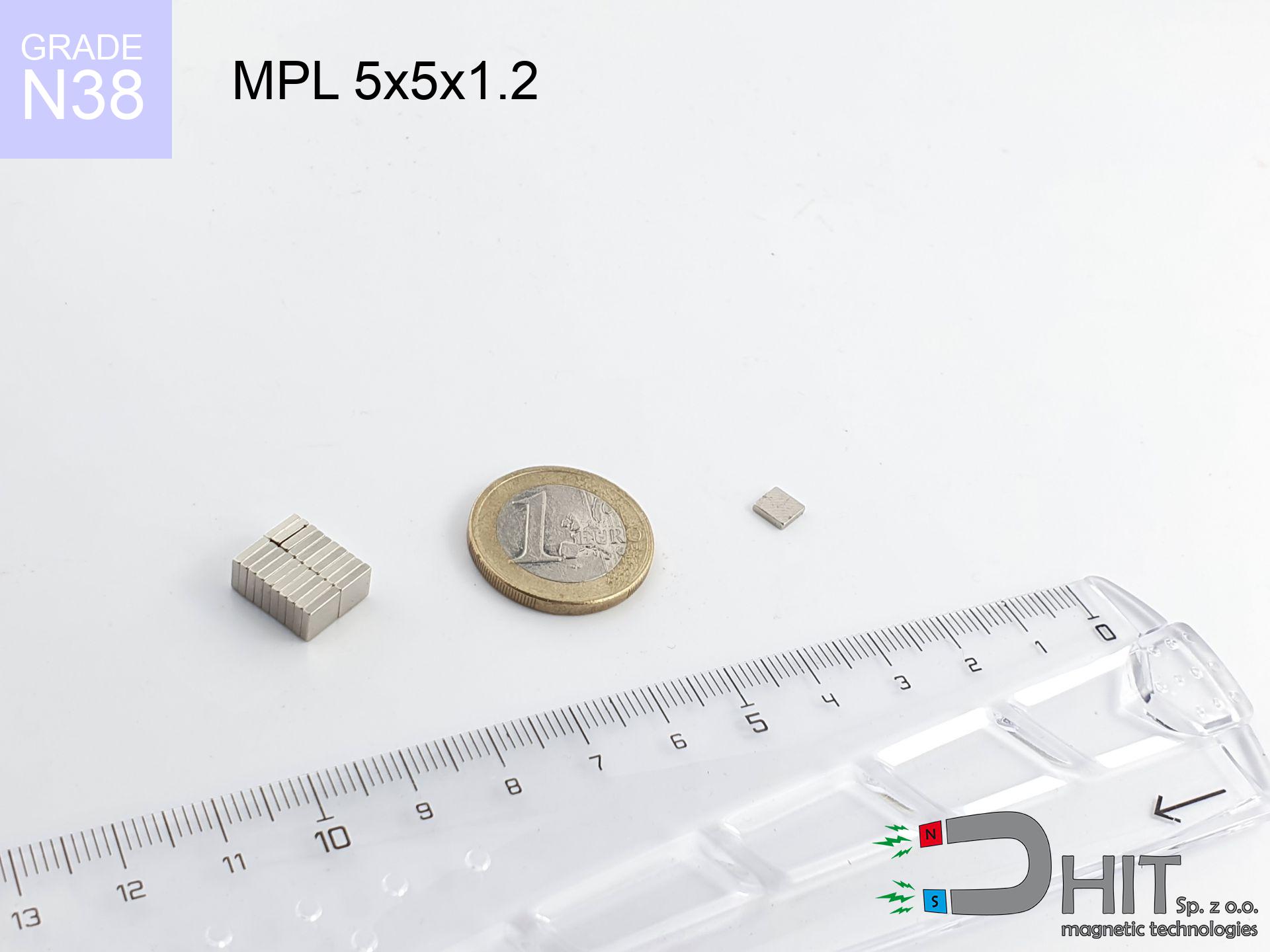
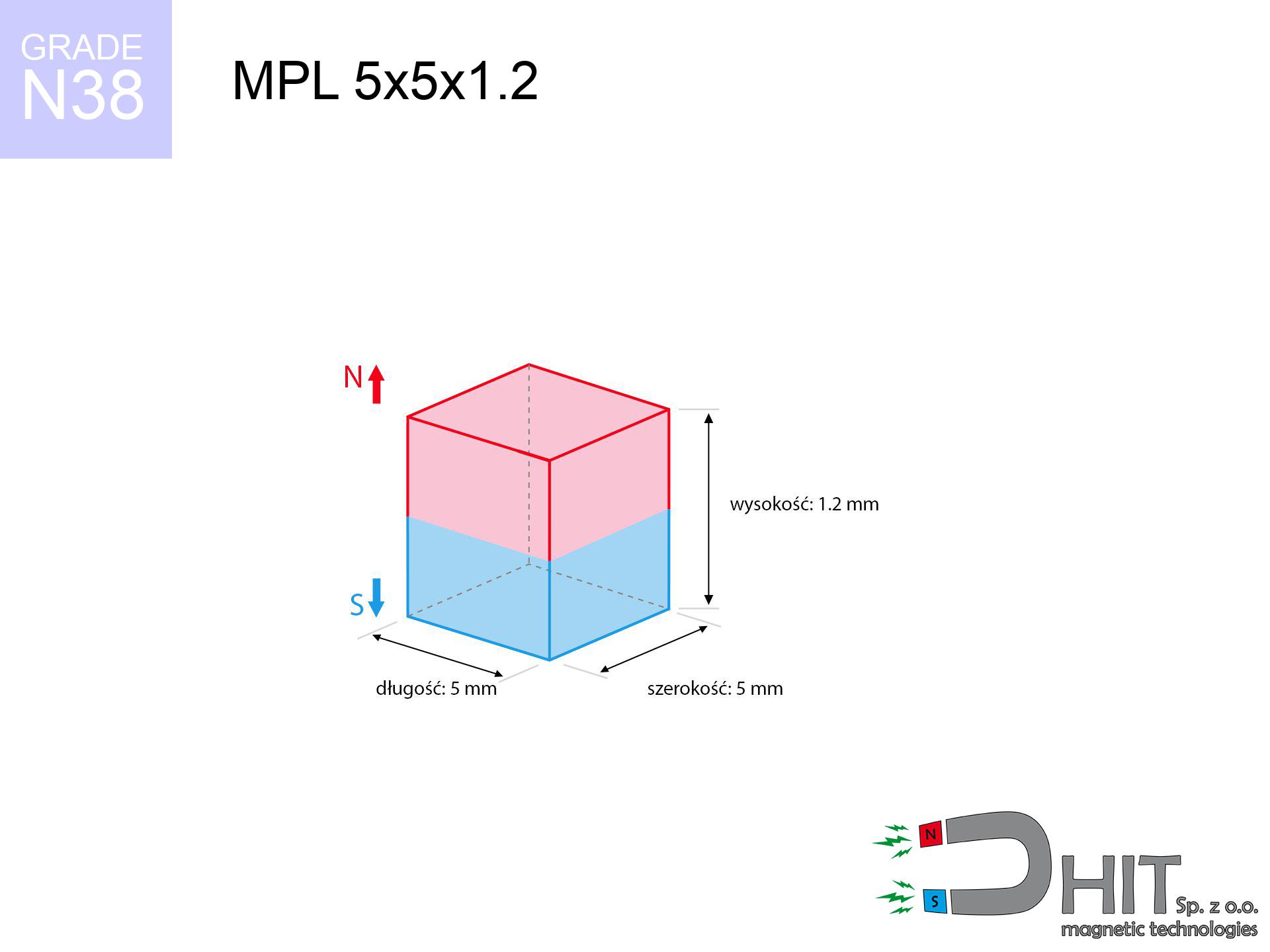
MPL 5x5x1.2 / N38 - lamellar magnet
lamellar magnet
Catalog no 020171
GTIN/EAN: 5906301811770
length
5 mm [±0,1 mm]
Width
5 mm [±0,1 mm]
Height
1.2 mm [±0,1 mm]
Weight
0.22 g
Magnetization Direction
↑ axial
Load capacity
0.44 kg / 4.28 N
Magnetic Induction
245.17 mT / 2452 Gs
Coating
[NiCuNi] Nickel
0.1845 ZŁ with VAT / pcs + price for transport
0.1500 ZŁ net + 23% VAT / pcs
bulk discounts:
Need more?
Contact us by phone
+48 888 99 98 98
alternatively drop us a message via
request form
our website.
Weight and form of neodymium magnets can be calculated using our
our magnetic calculator.
Orders submitted before 14:00 will be dispatched today!
Physical properties - MPL 5x5x1.2 / N38 - lamellar magnet
Specification / characteristics - MPL 5x5x1.2 / N38 - lamellar magnet
| properties | values |
|---|---|
| Cat. no. | 020171 |
| GTIN/EAN | 5906301811770 |
| Production/Distribution | Dhit sp. z o.o. |
| Country of origin | Poland / China / Germany |
| Customs code | 85059029 |
| length | 5 mm [±0,1 mm] |
| Width | 5 mm [±0,1 mm] |
| Height | 1.2 mm [±0,1 mm] |
| Weight | 0.22 g |
| Magnetization Direction | ↑ axial |
| Load capacity ~ ? | 0.44 kg / 4.28 N |
| Magnetic Induction ~ ? | 245.17 mT / 2452 Gs |
| Coating | [NiCuNi] Nickel |
| Manufacturing Tolerance | ±0.1 mm |
Magnetic properties of material N38
| properties | values | units |
|---|---|---|
| remenance Br [min. - max.] ? | 12.2-12.6 | kGs |
| remenance Br [min. - max.] ? | 1220-1260 | mT |
| coercivity bHc ? | 10.8-11.5 | kOe |
| coercivity bHc ? | 860-915 | kA/m |
| actual internal force iHc | ≥ 12 | kOe |
| actual internal force iHc | ≥ 955 | kA/m |
| energy density [min. - max.] ? | 36-38 | BH max MGOe |
| energy density [min. - max.] ? | 287-303 | BH max KJ/m |
| max. temperature ? | ≤ 80 | °C |
Physical properties of sintered neodymium magnets Nd2Fe14B at 20°C
| properties | values | units |
|---|---|---|
| Vickers hardness | ≥550 | Hv |
| Density | ≥7.4 | g/cm3 |
| Curie Temperature TC | 312 - 380 | °C |
| Curie Temperature TF | 593 - 716 | °F |
| Specific resistance | 150 | μΩ⋅cm |
| Bending strength | 250 | MPa |
| Compressive strength | 1000~1100 | MPa |
| Thermal expansion parallel (∥) to orientation (M) | (3-4) x 10-6 | °C-1 |
| Thermal expansion perpendicular (⊥) to orientation (M) | -(1-3) x 10-6 | °C-1 |
| Young's modulus | 1.7 x 10⁴ | kg/mm² |
Technical modeling of the assembly - data
These values are the result of a physical analysis. Results are based on algorithms for the class Nd2Fe14B. Operational parameters might slightly deviate from the simulation results. Please consider these data as a supplementary guide when designing systems.
Table 1: Static force (force vs distance) - power drop
MPL 5x5x1.2 / N38
| Distance (mm) | Induction (Gauss) / mT | Pull Force (kg/lbs/g/N) | Risk Status |
|---|---|---|---|
| 0 mm |
2450 Gs
245.0 mT
|
0.44 kg / 0.97 LBS
440.0 g / 4.3 N
|
low risk |
| 1 mm |
1739 Gs
173.9 mT
|
0.22 kg / 0.49 LBS
221.8 g / 2.2 N
|
low risk |
| 2 mm |
1054 Gs
105.4 mT
|
0.08 kg / 0.18 LBS
81.4 g / 0.8 N
|
low risk |
| 3 mm |
622 Gs
62.2 mT
|
0.03 kg / 0.06 LBS
28.4 g / 0.3 N
|
low risk |
| 5 mm |
241 Gs
24.1 mT
|
0.00 kg / 0.01 LBS
4.3 g / 0.0 N
|
low risk |
| 10 mm |
45 Gs
4.5 mT
|
0.00 kg / 0.00 LBS
0.1 g / 0.0 N
|
low risk |
| 15 mm |
15 Gs
1.5 mT
|
0.00 kg / 0.00 LBS
0.0 g / 0.0 N
|
low risk |
| 20 mm |
7 Gs
0.7 mT
|
0.00 kg / 0.00 LBS
0.0 g / 0.0 N
|
low risk |
| 30 mm |
2 Gs
0.2 mT
|
0.00 kg / 0.00 LBS
0.0 g / 0.0 N
|
low risk |
| 50 mm |
0 Gs
0.0 mT
|
0.00 kg / 0.00 LBS
0.0 g / 0.0 N
|
low risk |
Table 2: Shear force (wall)
MPL 5x5x1.2 / N38
| Distance (mm) | Friction coefficient | Pull Force (kg/lbs/g/N) |
|---|---|---|
| 0 mm | Stal (~0.2) |
0.09 kg / 0.19 LBS
88.0 g / 0.9 N
|
| 1 mm | Stal (~0.2) |
0.04 kg / 0.10 LBS
44.0 g / 0.4 N
|
| 2 mm | Stal (~0.2) |
0.02 kg / 0.04 LBS
16.0 g / 0.2 N
|
| 3 mm | Stal (~0.2) |
0.01 kg / 0.01 LBS
6.0 g / 0.1 N
|
| 5 mm | Stal (~0.2) |
0.00 kg / 0.00 LBS
0.0 g / 0.0 N
|
| 10 mm | Stal (~0.2) |
0.00 kg / 0.00 LBS
0.0 g / 0.0 N
|
| 15 mm | Stal (~0.2) |
0.00 kg / 0.00 LBS
0.0 g / 0.0 N
|
| 20 mm | Stal (~0.2) |
0.00 kg / 0.00 LBS
0.0 g / 0.0 N
|
| 30 mm | Stal (~0.2) |
0.00 kg / 0.00 LBS
0.0 g / 0.0 N
|
| 50 mm | Stal (~0.2) |
0.00 kg / 0.00 LBS
0.0 g / 0.0 N
|
Table 3: Vertical assembly (shearing) - behavior on slippery surfaces
MPL 5x5x1.2 / N38
| Surface type | Friction coefficient / % Mocy | Max load (kg/lbs/g/N) |
|---|---|---|
| Raw steel |
µ = 0.3
30% Nominalnej Siły
|
0.13 kg / 0.29 LBS
132.0 g / 1.3 N
|
| Painted steel (standard) |
µ = 0.2
20% Nominalnej Siły
|
0.09 kg / 0.19 LBS
88.0 g / 0.9 N
|
| Oily/slippery steel |
µ = 0.1
10% Nominalnej Siły
|
0.04 kg / 0.10 LBS
44.0 g / 0.4 N
|
| Magnet with anti-slip rubber |
µ = 0.5
50% Nominalnej Siły
|
0.22 kg / 0.49 LBS
220.0 g / 2.2 N
|
Table 4: Steel thickness (substrate influence) - sheet metal selection
MPL 5x5x1.2 / N38
| Steel thickness (mm) | % power | Real pull force (kg/lbs/g/N) |
|---|---|---|
| 0.5 mm |
|
0.04 kg / 0.10 LBS
44.0 g / 0.4 N
|
| 1 mm |
|
0.11 kg / 0.24 LBS
110.0 g / 1.1 N
|
| 2 mm |
|
0.22 kg / 0.49 LBS
220.0 g / 2.2 N
|
| 3 mm |
|
0.33 kg / 0.73 LBS
330.0 g / 3.2 N
|
| 5 mm |
|
0.44 kg / 0.97 LBS
440.0 g / 4.3 N
|
| 10 mm |
|
0.44 kg / 0.97 LBS
440.0 g / 4.3 N
|
| 11 mm |
|
0.44 kg / 0.97 LBS
440.0 g / 4.3 N
|
| 12 mm |
|
0.44 kg / 0.97 LBS
440.0 g / 4.3 N
|
Table 5: Thermal resistance (stability) - power drop
MPL 5x5x1.2 / N38
| Ambient temp. (°C) | Power loss | Remaining pull (kg/lbs/g/N) | Status |
|---|---|---|---|
| 20 °C | 0.0% |
0.44 kg / 0.97 LBS
440.0 g / 4.3 N
|
OK |
| 40 °C | -2.2% |
0.43 kg / 0.95 LBS
430.3 g / 4.2 N
|
OK |
| 60 °C | -4.4% |
0.42 kg / 0.93 LBS
420.6 g / 4.1 N
|
|
| 80 °C | -6.6% |
0.41 kg / 0.91 LBS
411.0 g / 4.0 N
|
|
| 100 °C | -28.8% |
0.31 kg / 0.69 LBS
313.3 g / 3.1 N
|
Table 6: Two magnets (repulsion) - field range
MPL 5x5x1.2 / N38
| Gap (mm) | Attraction (kg/lbs) (N-S) | Lateral Force (kg/lbs/g/N) | Repulsion (kg/lbs) (N-N) |
|---|---|---|---|
| 0 mm |
0.92 kg / 2.04 LBS
4 027 Gs
|
0.14 kg / 0.31 LBS
139 g / 1.4 N
|
N/A |
| 1 mm |
0.70 kg / 1.54 LBS
4 260 Gs
|
0.10 kg / 0.23 LBS
105 g / 1.0 N
|
0.63 kg / 1.39 LBS
~0 Gs
|
| 2 mm |
0.47 kg / 1.03 LBS
3 478 Gs
|
0.07 kg / 0.15 LBS
70 g / 0.7 N
|
0.42 kg / 0.93 LBS
~0 Gs
|
| 3 mm |
0.29 kg / 0.63 LBS
2 734 Gs
|
0.04 kg / 0.10 LBS
43 g / 0.4 N
|
0.26 kg / 0.57 LBS
~0 Gs
|
| 5 mm |
0.10 kg / 0.22 LBS
1 617 Gs
|
0.02 kg / 0.03 LBS
15 g / 0.1 N
|
0.09 kg / 0.20 LBS
~0 Gs
|
| 10 mm |
0.01 kg / 0.02 LBS
482 Gs
|
0.00 kg / 0.00 LBS
1 g / 0.0 N
|
0.00 kg / 0.00 LBS
~0 Gs
|
| 20 mm |
0.00 kg / 0.00 LBS
90 Gs
|
0.00 kg / 0.00 LBS
0 g / 0.0 N
|
0.00 kg / 0.00 LBS
~0 Gs
|
| 50 mm |
0.00 kg / 0.00 LBS
7 Gs
|
0.00 kg / 0.00 LBS
0 g / 0.0 N
|
0.00 kg / 0.00 LBS
~0 Gs
|
| 60 mm |
0.00 kg / 0.00 LBS
4 Gs
|
0.00 kg / 0.00 LBS
0 g / 0.0 N
|
0.00 kg / 0.00 LBS
~0 Gs
|
| 70 mm |
0.00 kg / 0.00 LBS
3 Gs
|
0.00 kg / 0.00 LBS
0 g / 0.0 N
|
0.00 kg / 0.00 LBS
~0 Gs
|
| 80 mm |
0.00 kg / 0.00 LBS
2 Gs
|
0.00 kg / 0.00 LBS
0 g / 0.0 N
|
0.00 kg / 0.00 LBS
~0 Gs
|
| 90 mm |
0.00 kg / 0.00 LBS
1 Gs
|
0.00 kg / 0.00 LBS
0 g / 0.0 N
|
0.00 kg / 0.00 LBS
~0 Gs
|
| 100 mm |
0.00 kg / 0.00 LBS
1 Gs
|
0.00 kg / 0.00 LBS
0 g / 0.0 N
|
0.00 kg / 0.00 LBS
~0 Gs
|
Table 7: Safety (HSE) (implants) - precautionary measures
MPL 5x5x1.2 / N38
| Object / Device | Limit (Gauss) / mT | Safe distance |
|---|---|---|
| Pacemaker | 5 Gs (0.5 mT) | 2.5 cm |
| Hearing aid | 10 Gs (1.0 mT) | 2.0 cm |
| Timepiece | 20 Gs (2.0 mT) | 1.5 cm |
| Phone / Smartphone | 40 Gs (4.0 mT) | 1.5 cm |
| Car key | 50 Gs (5.0 mT) | 1.0 cm |
| Payment card | 400 Gs (40.0 mT) | 0.5 cm |
| HDD hard drive | 600 Gs (60.0 mT) | 0.5 cm |
Table 8: Impact energy (cracking risk) - collision effects
MPL 5x5x1.2 / N38
| Start from (mm) | Speed (km/h) | Energy (J) | Predicted outcome |
|---|---|---|---|
| 10 mm |
45.11 km/h
(12.53 m/s)
|
0.02 J | |
| 30 mm |
78.12 km/h
(21.70 m/s)
|
0.05 J | |
| 50 mm |
100.85 km/h
(28.01 m/s)
|
0.09 J | |
| 100 mm |
142.63 km/h
(39.62 m/s)
|
0.17 J |
Table 9: Coating parameters (durability)
MPL 5x5x1.2 / N38
| Technical parameter | Value / Description |
|---|---|
| Coating type | [NiCuNi] Nickel |
| Layer structure | Nickel - Copper - Nickel |
| Layer thickness | 10-20 µm |
| Salt spray test (SST) ? | 24 h |
| Recommended environment | Indoors only (dry) |
Table 10: Construction data (Flux)
MPL 5x5x1.2 / N38
| Parameter | Value | SI Unit / Description |
|---|---|---|
| Magnetic Flux | 695 Mx | 7.0 µWb |
| Pc Coefficient | 0.30 | Low (Flat) |
Table 11: Submerged application
MPL 5x5x1.2 / N38
| Environment | Effective steel pull | Effect |
|---|---|---|
| Air (land) | 0.44 kg | Standard |
| Water (riverbed) |
0.50 kg
(+0.06 kg buoyancy gain)
|
+14.5% |
1. Vertical hold
*Warning: On a vertical surface, the magnet retains just ~20% of its nominal pull.
2. Steel saturation
*Thin steel (e.g. computer case) significantly reduces the holding force.
3. Heat tolerance
*For N38 material, the safety limit is 80°C.
4. Demagnetization curve and operating point (B-H)
chart generated for the permeance coefficient Pc (Permeance Coefficient) = 0.30
The chart above illustrates the magnetic characteristics of the material within the second quadrant of the hysteresis loop. The solid red line represents the demagnetization curve (material potential), while the dashed blue line is the load line based on the magnet's geometry. The Pc (Permeance Coefficient), also known as the load line slope, is a dimensionless value that describes the relationship between the magnet's shape and its magnetic stability. The intersection of these two lines (the black dot) is the operating point — it determines the actual magnetic flux density generated by the magnet in this specific configuration. A higher Pc value means the magnet is more 'slender' (tall relative to its area), resulting in a higher operating point and better resistance to irreversible demagnetization caused by external fields or temperature. A value of 0.42 is relatively low (typical for flat magnets), meaning the operating point is closer to the 'knee' of the curve — caution is advised when operating at temperatures near the maximum limit to avoid strength loss.
Material specification
| iron (Fe) | 64% – 68% |
| neodymium (Nd) | 29% – 32% |
| boron (B) | 1.1% – 1.2% |
| dysprosium (Dy) | 0.5% – 2.0% |
| coating (Ni-Cu-Ni) | < 0.05% |
Sustainability
| recyclability (EoL) | 100% |
| recycled raw materials | ~10% (pre-cons) |
| carbon footprint | low / zredukowany |
| waste code (EWC) | 16 02 16 |
Other proposals


![AM ucho [M8] - magnetic accessories](https://cdn3.dhit.pl/graphics/products/am-ucho-m8-lib.jpg "AM ucho [M8] - magnetic accessories")

Advantages as well as disadvantages of Nd2Fe14B magnets.
Strengths
- Their power is maintained, and after around ten years it decreases only by ~1% (theoretically),
- They are resistant to demagnetization induced by external disturbances,
- A magnet with a shiny nickel surface looks better,
- They are known for high magnetic induction at the operating surface, which affects their effectiveness,
- Thanks to resistance to high temperature, they are capable of working (depending on the form) even at temperatures up to 230°C and higher...
- Thanks to flexibility in designing and the ability to adapt to individual projects,
- Universal use in electronics industry – they serve a role in computer drives, electric motors, diagnostic systems, as well as modern systems.
- Compactness – despite small sizes they generate large force, making them ideal for precision applications
Cons
- At strong impacts they can crack, therefore we advise placing them in special holders. A metal housing provides additional protection against damage and increases the magnet's durability.
- We warn that neodymium magnets can lose their strength at high temperatures. To prevent this, we recommend our specialized [AH] magnets, which work effectively even at 230°C.
- When exposed to humidity, magnets usually rust. To use them in conditions outside, it is recommended to use protective magnets, such as those in rubber or plastics, which secure oxidation and corrosion.
- Due to limitations in producing nuts and complicated shapes in magnets, we recommend using casing - magnetic holder.
- Potential hazard to health – tiny shards of magnets are risky, if swallowed, which gains importance in the context of child safety. It is also worth noting that small components of these products can disrupt the diagnostic process medical when they are in the body.
- Higher cost of purchase is one of the disadvantages compared to ceramic magnets, especially in budget applications
Pull force analysis
Magnetic strength at its maximum – what affects it?
- using a sheet made of low-carbon steel, functioning as a magnetic yoke
- whose thickness equals approx. 10 mm
- characterized by even structure
- without the slightest air gap between the magnet and steel
- for force applied at a right angle (pull-off, not shear)
- at conditions approx. 20°C
Practical lifting capacity: influencing factors
- Air gap (between the magnet and the plate), since even a microscopic distance (e.g. 0.5 mm) leads to a reduction in force by up to 50% (this also applies to varnish, corrosion or debris).
- Force direction – declared lifting capacity refers to pulling vertically. When attempting to slide, the magnet exhibits significantly lower power (typically approx. 20-30% of nominal force).
- Plate thickness – too thin steel does not accept the full field, causing part of the power to be escaped into the air.
- Steel type – low-carbon steel attracts best. Alloy steels reduce magnetic properties and holding force.
- Smoothness – full contact is possible only on polished steel. Rough texture reduce the real contact area, weakening the magnet.
- Thermal factor – high temperature reduces magnetic field. Too high temperature can permanently demagnetize the magnet.
Lifting capacity was determined by applying a smooth steel plate of optimal thickness (min. 20 mm), under perpendicular detachment force, however under parallel forces the lifting capacity is smaller. Additionally, even a slight gap between the magnet’s surface and the plate reduces the lifting capacity.
Safe handling of neodymium magnets
Pinching danger
Watch your fingers. Two powerful magnets will join instantly with a force of massive weight, destroying everything in their path. Exercise extreme caution!
Magnetic interference
GPS units and smartphones are highly sensitive to magnetism. Direct contact with a powerful NdFeB magnet can decalibrate the sensors in your phone.
Dust explosion hazard
Machining of neodymium magnets poses a fire risk. Magnetic powder oxidizes rapidly with oxygen and is hard to extinguish.
Thermal limits
Standard neodymium magnets (N-type) undergo demagnetization when the temperature surpasses 80°C. The loss of strength is permanent.
Keep away from children
Product intended for adults. Small elements can be swallowed, leading to serious injuries. Store out of reach of kids and pets.
ICD Warning
Patients with a ICD should maintain an safe separation from magnets. The magnetism can interfere with the functioning of the implant.
Sensitization to coating
Allergy Notice: The nickel-copper-nickel coating consists of nickel. If an allergic reaction occurs, immediately stop working with magnets and use protective gear.
Material brittleness
Watch out for shards. Magnets can fracture upon violent connection, launching sharp fragments into the air. Eye protection is mandatory.
Electronic hazard
Device Safety: Neodymium magnets can ruin payment cards and sensitive devices (heart implants, medical aids, timepieces).
Do not underestimate power
Use magnets with awareness. Their huge power can surprise even professionals. Plan your moves and do not underestimate their force.
Tabela kosztu i czasu dostawy
Płatność przed wysyłką:

GLS kurier
Przesyłka będzie u Ciebie za 2-3 dni
14.99 ZŁ

InPost Paczkomaty 24/7
Przesyłka będzie u Ciebie za 1-2 dni
12.30 ZŁ
Płatność przy odbiorze (pobranie):
GLS kurier
Przesyłka będzie u Ciebie za 1-2 dni
23.00 ZŁ
Rate the product
Your rating