
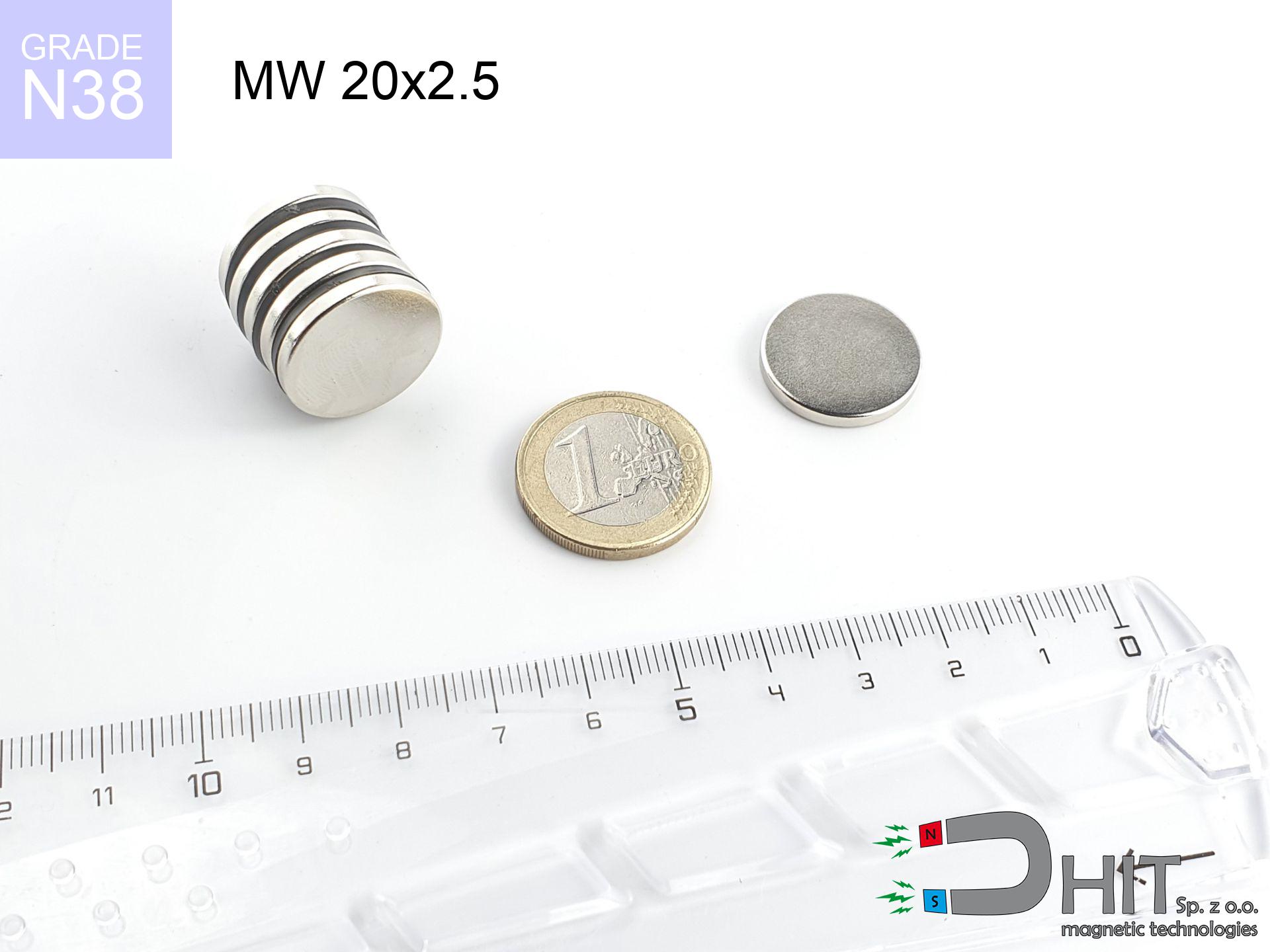
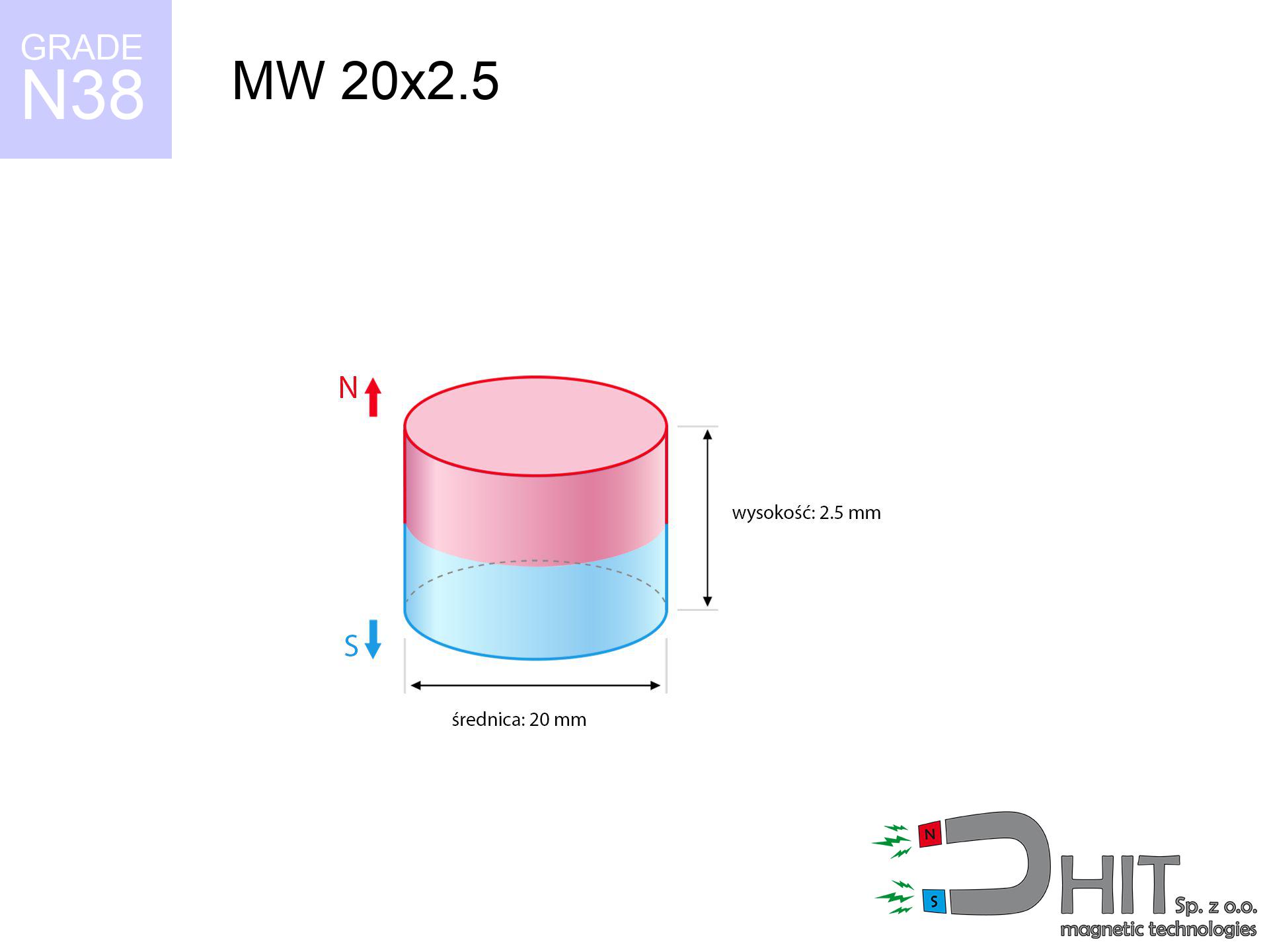
MW 20x2.5 / N38 - cylindrical magnet
cylindrical magnet
Catalog no 010042
GTIN/EAN: 5906301810414
Diameter Ø
20 mm [±0,1 mm]
Height
2.5 mm [±0,1 mm]
Weight
5.89 g
Magnetization Direction
↑ axial
Load capacity
2.41 kg / 23.63 N
Magnetic Induction
150.34 mT / 1503 Gs
Coating
[NiCuNi] Nickel
3.01 ZŁ with VAT / pcs + price for transport
2.45 ZŁ net + 23% VAT / pcs
bulk discounts:
Need more?Engineering report for this magnet
Full PDF analysis: pull and shear force, effect of distance, temperature and plate thickness, safety distances and the demagnetization curve.
Give us a call
+48 888 99 98 98
alternatively get in touch by means of
request form
through our site.
Lifting power along with appearance of a neodymium magnet can be calculated on our
force calculator.
Same-day processing for orders placed before 14:00.
Technical details - MW 20x2.5 / N38 - cylindrical magnet
Specification / characteristics - MW 20x2.5 / N38 - cylindrical magnet
| properties | values |
|---|---|
| Cat. no. | 010042 |
| GTIN/EAN | 5906301810414 |
| Production/Distribution | Dhit sp. z o.o. |
| Country of origin | Poland / China / Germany |
| Customs code | 85059029 |
| Diameter Ø | 20 mm [±0,1 mm] |
| Height | 2.5 mm [±0,1 mm] |
| Weight | 5.89 g |
| Magnetization Direction | ↑ axial |
| Load capacity ~ ? | 2.41 kg / 23.63 N |
| Magnetic Induction ~ ? | 150.34 mT / 1503 Gs |
| Coating | [NiCuNi] Nickel |
| Manufacturing Tolerance | ±0.1 mm |
Magnetic properties of material N38
| properties | values | units |
|---|---|---|
| remenance Br [min. - max.] ? | 12.2-12.6 | kGs |
| remenance Br [min. - max.] ? | 1220-1260 | mT |
| coercivity bHc ? | 10.8-11.5 | kOe |
| coercivity bHc ? | 860-915 | kA/m |
| actual internal force iHc | ≥ 12 | kOe |
| actual internal force iHc | ≥ 955 | kA/m |
| energy density [min. - max.] ? | 36-38 | BH max MGOe |
| energy density [min. - max.] ? | 287-303 | BH max KJ/m |
| max. temperature ? | ≤ 80 | °C |
Physical properties of sintered neodymium magnets Nd2Fe14B at 20°C
| properties | values | units |
|---|---|---|
| Vickers hardness | ≥550 | Hv |
| Density | ≥7.4 | g/cm3 |
| Curie Temperature TC | 312 - 380 | °C |
| Curie Temperature TF | 593 - 716 | °F |
| Specific resistance | 150 | μΩ⋅cm |
| Bending strength | 250 | MPa |
| Compressive strength | 1000~1100 | MPa |
| Thermal expansion parallel (∥) to orientation (M) | (3-4) x 10-6 | °C-1 |
| Thermal expansion perpendicular (⊥) to orientation (M) | -(1-3) x 10-6 | °C-1 |
| Young's modulus | 1.7 x 10⁴ | kg/mm² |
Technical simulation of the assembly - report
Presented values constitute the outcome of a physical analysis. Values are based on models for the class Nd2Fe14B. Real-world performance might slightly deviate from the simulation results. Treat these calculations as a supplementary guide for designers.
Table 1: Static force (pull vs distance) - characteristics
MW 20x2.5 / N38
| Distance (mm) | Induction (Gauss) / mT | Pull Force (kg/lbs/g/N) | Risk Status |
|---|---|---|---|
| 0 mm |
1503 Gs
150.3 mT
|
2.41 kg / 5.31 pounds
2410.0 g / 23.6 N
|
strong |
| 1 mm |
1431 Gs
143.1 mT
|
2.18 kg / 4.82 pounds
2184.9 g / 21.4 N
|
strong |
| 2 mm |
1328 Gs
132.8 mT
|
1.88 kg / 4.15 pounds
1882.0 g / 18.5 N
|
safe |
| 3 mm |
1206 Gs
120.6 mT
|
1.55 kg / 3.42 pounds
1552.2 g / 15.2 N
|
safe |
| 5 mm |
947 Gs
94.7 mT
|
0.96 kg / 2.11 pounds
957.1 g / 9.4 N
|
safe |
| 10 mm |
457 Gs
45.7 mT
|
0.22 kg / 0.49 pounds
223.1 g / 2.2 N
|
safe |
| 15 mm |
224 Gs
22.4 mT
|
0.05 kg / 0.12 pounds
53.7 g / 0.5 N
|
safe |
| 20 mm |
120 Gs
12.0 mT
|
0.02 kg / 0.03 pounds
15.4 g / 0.2 N
|
safe |
| 30 mm |
44 Gs
4.4 mT
|
0.00 kg / 0.00 pounds
2.1 g / 0.0 N
|
safe |
| 50 mm |
11 Gs
1.1 mT
|
0.00 kg / 0.00 pounds
0.1 g / 0.0 N
|
safe |
Table 2: Shear hold (vertical surface)
MW 20x2.5 / N38
| Distance (mm) | Friction coefficient | Pull Force (kg/lbs/g/N) |
|---|---|---|
| 0 mm | Stal (~0.2) |
0.48 kg / 1.06 pounds
482.0 g / 4.7 N
|
| 1 mm | Stal (~0.2) |
0.44 kg / 0.96 pounds
436.0 g / 4.3 N
|
| 2 mm | Stal (~0.2) |
0.38 kg / 0.83 pounds
376.0 g / 3.7 N
|
| 3 mm | Stal (~0.2) |
0.31 kg / 0.68 pounds
310.0 g / 3.0 N
|
| 5 mm | Stal (~0.2) |
0.19 kg / 0.42 pounds
192.0 g / 1.9 N
|
| 10 mm | Stal (~0.2) |
0.04 kg / 0.10 pounds
44.0 g / 0.4 N
|
| 15 mm | Stal (~0.2) |
0.01 kg / 0.02 pounds
10.0 g / 0.1 N
|
| 20 mm | Stal (~0.2) |
0.00 kg / 0.01 pounds
4.0 g / 0.0 N
|
| 30 mm | Stal (~0.2) |
0.00 kg / 0.00 pounds
0.0 g / 0.0 N
|
| 50 mm | Stal (~0.2) |
0.00 kg / 0.00 pounds
0.0 g / 0.0 N
|
Table 3: Vertical assembly (shearing) - vertical pull
MW 20x2.5 / N38
| Surface type | Friction coefficient / % Mocy | Max load (kg/lbs/g/N) |
|---|---|---|
| Raw steel |
µ = 0.3
30% Nominalnej Siły
|
0.72 kg / 1.59 pounds
723.0 g / 7.1 N
|
| Painted steel (standard) |
µ = 0.2
20% Nominalnej Siły
|
0.48 kg / 1.06 pounds
482.0 g / 4.7 N
|
| Oily/slippery steel |
µ = 0.1
10% Nominalnej Siły
|
0.24 kg / 0.53 pounds
241.0 g / 2.4 N
|
| Magnet with anti-slip rubber |
µ = 0.5
50% Nominalnej Siły
|
1.21 kg / 2.66 pounds
1205.0 g / 11.8 N
|
Table 4: Steel thickness (substrate influence) - power losses
MW 20x2.5 / N38
| Steel thickness (mm) | % power | Real pull force (kg/lbs/g/N) |
|---|---|---|
| 0.5 mm |
|
0.24 kg / 0.53 pounds
241.0 g / 2.4 N
|
| 1 mm |
|
0.60 kg / 1.33 pounds
602.5 g / 5.9 N
|
| 2 mm |
|
1.21 kg / 2.66 pounds
1205.0 g / 11.8 N
|
| 3 mm |
|
1.81 kg / 3.98 pounds
1807.5 g / 17.7 N
|
| 5 mm |
|
2.41 kg / 5.31 pounds
2410.0 g / 23.6 N
|
| 10 mm |
|
2.41 kg / 5.31 pounds
2410.0 g / 23.6 N
|
| 11 mm |
|
2.41 kg / 5.31 pounds
2410.0 g / 23.6 N
|
| 12 mm |
|
2.41 kg / 5.31 pounds
2410.0 g / 23.6 N
|
Table 5: Thermal resistance (stability) - thermal limit
MW 20x2.5 / N38
| Ambient temp. (°C) | Power loss | Remaining pull (kg/lbs/g/N) | Status |
|---|---|---|---|
| 20 °C | 0.0% |
2.41 kg / 5.31 pounds
2410.0 g / 23.6 N
|
OK |
| 40 °C | -2.2% |
2.36 kg / 5.20 pounds
2357.0 g / 23.1 N
|
OK |
| 60 °C | -4.4% |
2.30 kg / 5.08 pounds
2304.0 g / 22.6 N
|
|
| 80 °C | -6.6% |
2.25 kg / 4.96 pounds
2250.9 g / 22.1 N
|
|
| 100 °C | -28.8% |
1.72 kg / 3.78 pounds
1715.9 g / 16.8 N
|
Table 6: Two magnets (repulsion) - field collision
MW 20x2.5 / N38
| Gap (mm) | Attraction (kg/lbs) (N-S) | Lateral Force (kg/lbs/g/N) | Repulsion (kg/lbs) (N-N) |
|---|---|---|---|
| 0 mm |
4.38 kg / 9.65 pounds
2 771 Gs
|
0.66 kg / 1.45 pounds
656 g / 6.4 N
|
N/A |
| 1 mm |
4.20 kg / 9.25 pounds
2 944 Gs
|
0.63 kg / 1.39 pounds
629 g / 6.2 N
|
3.78 kg / 8.33 pounds
~0 Gs
|
| 2 mm |
3.97 kg / 8.75 pounds
2 862 Gs
|
0.60 kg / 1.31 pounds
595 g / 5.8 N
|
3.57 kg / 7.87 pounds
~0 Gs
|
| 3 mm |
3.70 kg / 8.17 pounds
2 766 Gs
|
0.56 kg / 1.22 pounds
556 g / 5.5 N
|
3.33 kg / 7.35 pounds
~0 Gs
|
| 5 mm |
3.12 kg / 6.88 pounds
2 538 Gs
|
0.47 kg / 1.03 pounds
468 g / 4.6 N
|
2.81 kg / 6.19 pounds
~0 Gs
|
| 10 mm |
1.74 kg / 3.83 pounds
1 895 Gs
|
0.26 kg / 0.57 pounds
261 g / 2.6 N
|
1.56 kg / 3.45 pounds
~0 Gs
|
| 20 mm |
0.41 kg / 0.89 pounds
915 Gs
|
0.06 kg / 0.13 pounds
61 g / 0.6 N
|
0.36 kg / 0.80 pounds
~0 Gs
|
| 50 mm |
0.01 kg / 0.02 pounds
140 Gs
|
0.00 kg / 0.00 pounds
1 g / 0.0 N
|
0.00 kg / 0.00 pounds
~0 Gs
|
| 60 mm |
0.00 kg / 0.01 pounds
88 Gs
|
0.00 kg / 0.00 pounds
1 g / 0.0 N
|
0.00 kg / 0.00 pounds
~0 Gs
|
| 70 mm |
0.00 kg / 0.00 pounds
58 Gs
|
0.00 kg / 0.00 pounds
0 g / 0.0 N
|
0.00 kg / 0.00 pounds
~0 Gs
|
| 80 mm |
0.00 kg / 0.00 pounds
41 Gs
|
0.00 kg / 0.00 pounds
0 g / 0.0 N
|
0.00 kg / 0.00 pounds
~0 Gs
|
| 90 mm |
0.00 kg / 0.00 pounds
29 Gs
|
0.00 kg / 0.00 pounds
0 g / 0.0 N
|
0.00 kg / 0.00 pounds
~0 Gs
|
| 100 mm |
0.00 kg / 0.00 pounds
22 Gs
|
0.00 kg / 0.00 pounds
0 g / 0.0 N
|
0.00 kg / 0.00 pounds
~0 Gs
|
Table 7: Protective zones (implants) - warnings
MW 20x2.5 / N38
| Object / Device | Limit (Gauss) / mT | Safe distance |
|---|---|---|
| Pacemaker | 5 Gs (0.5 mT) | 7.0 cm |
| Hearing aid | 10 Gs (1.0 mT) | 5.5 cm |
| Mechanical watch | 20 Gs (2.0 mT) | 4.5 cm |
| Phone / Smartphone | 40 Gs (4.0 mT) | 3.5 cm |
| Car key | 50 Gs (5.0 mT) | 3.0 cm |
| Payment card | 400 Gs (40.0 mT) | 1.5 cm |
| HDD hard drive | 600 Gs (60.0 mT) | 1.0 cm |
Table 8: Collisions (kinetic energy) - warning
MW 20x2.5 / N38
| Start from (mm) | Speed (km/h) | Energy (J) | Predicted outcome |
|---|---|---|---|
| 10 mm |
21.89 km/h
(6.08 m/s)
|
0.11 J | |
| 30 mm |
22.67 km/h
(6.30 m/s)
|
0.12 J | |
| 50 mm |
22.68 km/h
(6.30 m/s)
|
0.12 J | |
| 100 mm |
22.68 km/h
(6.30 m/s)
|
0.12 J |
Table 9: Corrosion resistance
MW 20x2.5 / N38
| Technical parameter | Value / Description |
|---|---|
| Coating type | [NiCuNi] Nickel |
| Layer structure | Nickel - Copper - Nickel |
| Layer thickness | 10-20 µm |
| Salt spray test (SST) ? | 24 h |
| Recommended environment | Indoors only (dry) |
Table 10: Electrical data (Flux)
MW 20x2.5 / N38
| Parameter | Value | SI Unit / Description |
|---|---|---|
| Magnetic Flux | 5 996 Mx | 60.0 µWb |
| Pc Coefficient | 0.19 | Low (Flat) |
Table 11: Hydrostatics and buoyancy
MW 20x2.5 / N38
| Environment | Effective steel pull | Effect |
|---|---|---|
| Air (land) | 2.41 kg | Standard |
| Water (riverbed) |
2.76 kg
(+0.35 kg buoyancy gain)
|
+14.5% |
1. Sliding resistance
*Note: On a vertical surface, the magnet holds merely approx. 20-30% of its perpendicular strength.
2. Efficiency vs thickness
*Thin steel (e.g. computer case) significantly limits the holding force.
3. Thermal stability
*For N38 grade, the max working temp is 80°C.
4. Demagnetization curve and operating point (B-H)
chart generated for the permeance coefficient Pc (Permeance Coefficient) = 0.19
The chart above illustrates the magnetic characteristics of the material within the second quadrant of the hysteresis loop. The solid red line represents the demagnetization curve (material potential), while the dashed blue line is the load line based on the magnet's geometry. The Pc (Permeance Coefficient), also known as the load line slope, is a dimensionless value that describes the relationship between the magnet's shape and its magnetic stability. The intersection of these two lines (the black dot) is the operating point — it determines the actual magnetic flux density generated by the magnet in this specific configuration. A higher Pc value means the magnet is more 'slender' (tall relative to its area), resulting in a higher operating point and better resistance to irreversible demagnetization caused by external fields or temperature. A value of 0.42 is relatively low (typical for flat magnets), meaning the operating point is closer to the 'knee' of the curve — caution is advised when operating at temperatures near the maximum limit to avoid strength loss.
Chemical composition
| iron (Fe) | 64% – 68% |
| neodymium (Nd) | 29% – 32% |
| boron (B) | 1.1% – 1.2% |
| dysprosium (Dy) | 0.5% – 2.0% |
| coating (Ni-Cu-Ni) | < 0.05% |
Environmental data
| recyclability (EoL) | 100% |
| recycled raw materials | ~10% (pre-cons) |
| carbon footprint | low / zredukowany |
| waste code (EWC) | 16 02 16 |
Other deals


![UMP 107x40 [M8+M10] GW F400 Lina / N38 - search holder](https://cdn3.dhit.pl/graphics/products/ump-107x40-m8+m10-gw-f400-+lina-bel.jpg "UMP 107x40 [M8+M10] GW F400 Lina / N38 - search holder")
Strengths and weaknesses of neodymium magnets.
Strengths
- They do not lose power, even over around 10 years – the drop in strength is only ~1% (based on measurements),
- They are extremely resistant to demagnetization induced by external disturbances,
- By covering with a shiny layer of gold, the element has an modern look,
- Neodymium magnets ensure maximum magnetic induction on a small area, which ensures high operational effectiveness,
- Through (adequate) combination of ingredients, they can achieve high thermal strength, enabling action at temperatures approaching 230°C and above...
- Possibility of individual creating and adjusting to concrete needs,
- Key role in electronics industry – they are utilized in HDD drives, motor assemblies, diagnostic systems, also multitasking production systems.
- Relatively small size with high pulling force – neodymium magnets offer impressive pulling force in compact dimensions, which allows their use in miniature devices
Disadvantages
- At very strong impacts they can crack, therefore we advise placing them in steel cases. A metal housing provides additional protection against damage, as well as increases the magnet's durability.
- We warn that neodymium magnets can reduce their power at high temperatures. To prevent this, we recommend our specialized [AH] magnets, which work effectively even at 230°C.
- Magnets exposed to a humid environment can rust. Therefore when using outdoors, we recommend using water-impermeable magnets made of rubber, plastic or other material resistant to moisture
- Due to limitations in realizing nuts and complicated shapes in magnets, we propose using cover - magnetic holder.
- Health risk related to microscopic parts of magnets are risky, in case of ingestion, which is particularly important in the context of child health protection. Furthermore, tiny parts of these devices can disrupt the diagnostic process medical in case of swallowing.
- With mass production the cost of neodymium magnets is a challenge,
Holding force characteristics
Magnetic strength at its maximum – what it depends on?
- with the contact of a yoke made of special test steel, ensuring maximum field concentration
- possessing a massiveness of minimum 10 mm to ensure full flux closure
- with a plane perfectly flat
- without the slightest air gap between the magnet and steel
- for force acting at a right angle (in the magnet axis)
- in stable room temperature
Determinants of lifting force in real conditions
- Distance – existence of any layer (rust, tape, gap) acts as an insulator, which lowers power steeply (even by 50% at 0.5 mm).
- Angle of force application – highest force is available only during pulling at a 90° angle. The force required to slide of the magnet along the surface is typically several times smaller (approx. 1/5 of the lifting capacity).
- Substrate thickness – for full efficiency, the steel must be sufficiently thick. Paper-thin metal limits the attraction force (the magnet "punches through" it).
- Steel type – mild steel attracts best. Alloy steels decrease magnetic permeability and holding force.
- Plate texture – ground elements ensure maximum contact, which increases force. Uneven metal weaken the grip.
- Thermal environment – temperature increase results in weakening of induction. Check the maximum operating temperature for a given model.
Lifting capacity was assessed by applying a smooth steel plate of suitable thickness (min. 20 mm), under perpendicular pulling force, whereas under attempts to slide the magnet the load capacity is reduced by as much as 5 times. In addition, even a slight gap between the magnet’s surface and the plate reduces the holding force.
H&S for magnets
Do not underestimate power
Before starting, check safety instructions. Uncontrolled attraction can break the magnet or injure your hand. Be predictive.
Sensitization to coating
Nickel alert: The nickel-copper-nickel coating contains nickel. If skin irritation occurs, cease working with magnets and wear gloves.
Beware of splinters
Watch out for shards. Magnets can explode upon violent connection, ejecting sharp fragments into the air. Wear goggles.
Fire warning
Fire warning: Rare earth powder is explosive. Do not process magnets in home conditions as this may cause fire.
Heat warning
Regular neodymium magnets (grade N) undergo demagnetization when the temperature exceeds 80°C. Damage is permanent.
Danger to pacemakers
Patients with a pacemaker should maintain an safe separation from magnets. The magnetic field can disrupt the operation of the life-saving device.
Magnetic interference
A strong magnetic field negatively affects the operation of compasses in smartphones and navigation systems. Keep magnets close to a smartphone to prevent damaging the sensors.
Serious injuries
Protect your hands. Two large magnets will snap together instantly with a force of several hundred kilograms, destroying anything in their path. Be careful!
Swallowing risk
Neodymium magnets are not toys. Eating several magnets can lead to them pinching intestinal walls, which poses a critical condition and necessitates urgent medical intervention.
Data carriers
Very strong magnetic fields can corrupt files on payment cards, HDDs, and storage devices. Stay away of min. 10 cm.
Tabela kosztu i czasu dostawy
Płatność przed wysyłką:

GLS kurier
Przesyłka będzie u Ciebie za 2-3 dni
14.99 ZŁ

InPost Paczkomaty 24/7
Przesyłka będzie u Ciebie za 1-2 dni
12.30 ZŁ
Płatność przy odbiorze (pobranie):
GLS kurier
Przesyłka będzie u Ciebie za 1-2 dni
23.00 ZŁ
Rate the product
Your rating