

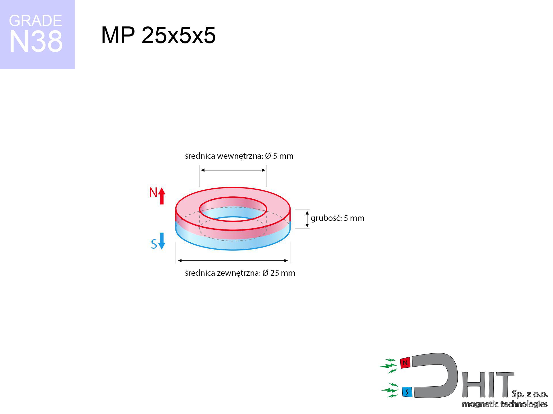
MP 25x5x5 / N38 - ring magnet
ring magnet
Catalog no 030193
GTIN/EAN: 5906301812104
Diameter
25 mm [±0,1 mm]
internal diameter Ø
5 mm [±0,1 mm]
Height
5 mm [±0,1 mm]
Weight
17.67 g
Magnetization Direction
↑ axial
Load capacity
7.66 kg / 75.12 N
Magnetic Induction
230.20 mT / 2302 Gs
Coating
[NiCuNi] Nickel
6.00 ZŁ with VAT / pcs + price for transport
4.88 ZŁ net + 23% VAT / pcs
bulk discounts:
Need more?
Contact us by phone
+48 888 99 98 98
if you prefer let us know by means of
inquiry form
through our site.
Lifting power along with appearance of magnets can be reviewed using our
online calculation tool.
Order by 14:00 and we’ll ship today!
Technical details - MP 25x5x5 / N38 - ring magnet
Specification / characteristics - MP 25x5x5 / N38 - ring magnet
| properties | values |
|---|---|
| Cat. no. | 030193 |
| GTIN/EAN | 5906301812104 |
| Production/Distribution | Dhit sp. z o.o. |
| Country of origin | Poland / China / Germany |
| Customs code | 85059029 |
| Diameter | 25 mm [±0,1 mm] |
| internal diameter Ø | 5 mm [±0,1 mm] |
| Height | 5 mm [±0,1 mm] |
| Weight | 17.67 g |
| Magnetization Direction | ↑ axial |
| Load capacity ~ ? | 7.66 kg / 75.12 N |
| Magnetic Induction ~ ? | 230.20 mT / 2302 Gs |
| Coating | [NiCuNi] Nickel |
| Manufacturing Tolerance | ±0.1 mm |
Magnetic properties of material N38
| properties | values | units |
|---|---|---|
| remenance Br [min. - max.] ? | 12.2-12.6 | kGs |
| remenance Br [min. - max.] ? | 1220-1260 | mT |
| coercivity bHc ? | 10.8-11.5 | kOe |
| coercivity bHc ? | 860-915 | kA/m |
| actual internal force iHc | ≥ 12 | kOe |
| actual internal force iHc | ≥ 955 | kA/m |
| energy density [min. - max.] ? | 36-38 | BH max MGOe |
| energy density [min. - max.] ? | 287-303 | BH max KJ/m |
| max. temperature ? | ≤ 80 | °C |
Physical properties of sintered neodymium magnets Nd2Fe14B at 20°C
| properties | values | units |
|---|---|---|
| Vickers hardness | ≥550 | Hv |
| Density | ≥7.4 | g/cm3 |
| Curie Temperature TC | 312 - 380 | °C |
| Curie Temperature TF | 593 - 716 | °F |
| Specific resistance | 150 | μΩ⋅cm |
| Bending strength | 250 | MPa |
| Compressive strength | 1000~1100 | MPa |
| Thermal expansion parallel (∥) to orientation (M) | (3-4) x 10-6 | °C-1 |
| Thermal expansion perpendicular (⊥) to orientation (M) | -(1-3) x 10-6 | °C-1 |
| Young's modulus | 1.7 x 10⁴ | kg/mm² |
Physical modeling of the assembly - technical parameters
Presented values are the result of a physical simulation. Results rely on models for the class Nd2Fe14B. Real-world conditions may deviate from the simulation results. Use these calculations as a supplementary guide during assembly planning.
Table 1: Static force (pull vs distance) - power drop
MP 25x5x5 / N38
| Distance (mm) | Induction (Gauss) / mT | Pull Force (kg/lbs/g/N) | Risk Status |
|---|---|---|---|
| 0 mm |
5777 Gs
577.7 mT
|
7.66 kg / 16.89 LBS
7660.0 g / 75.1 N
|
warning |
| 1 mm |
5310 Gs
531.0 mT
|
6.47 kg / 14.27 LBS
6471.0 g / 63.5 N
|
warning |
| 2 mm |
4846 Gs
484.6 mT
|
5.39 kg / 11.88 LBS
5388.6 g / 52.9 N
|
warning |
| 3 mm |
4397 Gs
439.7 mT
|
4.44 kg / 9.78 LBS
4437.9 g / 43.5 N
|
warning |
| 5 mm |
3576 Gs
357.6 mT
|
2.93 kg / 6.47 LBS
2934.8 g / 28.8 N
|
warning |
| 10 mm |
2073 Gs
207.3 mT
|
0.99 kg / 2.17 LBS
985.9 g / 9.7 N
|
weak grip |
| 15 mm |
1231 Gs
123.1 mT
|
0.35 kg / 0.77 LBS
347.9 g / 3.4 N
|
weak grip |
| 20 mm |
773 Gs
77.3 mT
|
0.14 kg / 0.30 LBS
137.0 g / 1.3 N
|
weak grip |
| 30 mm |
356 Gs
35.6 mT
|
0.03 kg / 0.06 LBS
29.0 g / 0.3 N
|
weak grip |
| 50 mm |
115 Gs
11.5 mT
|
0.00 kg / 0.01 LBS
3.0 g / 0.0 N
|
weak grip |
Table 2: Shear hold (vertical surface)
MP 25x5x5 / N38
| Distance (mm) | Friction coefficient | Pull Force (kg/lbs/g/N) |
|---|---|---|
| 0 mm | Stal (~0.2) |
1.53 kg / 3.38 LBS
1532.0 g / 15.0 N
|
| 1 mm | Stal (~0.2) |
1.29 kg / 2.85 LBS
1294.0 g / 12.7 N
|
| 2 mm | Stal (~0.2) |
1.08 kg / 2.38 LBS
1078.0 g / 10.6 N
|
| 3 mm | Stal (~0.2) |
0.89 kg / 1.96 LBS
888.0 g / 8.7 N
|
| 5 mm | Stal (~0.2) |
0.59 kg / 1.29 LBS
586.0 g / 5.7 N
|
| 10 mm | Stal (~0.2) |
0.20 kg / 0.44 LBS
198.0 g / 1.9 N
|
| 15 mm | Stal (~0.2) |
0.07 kg / 0.15 LBS
70.0 g / 0.7 N
|
| 20 mm | Stal (~0.2) |
0.03 kg / 0.06 LBS
28.0 g / 0.3 N
|
| 30 mm | Stal (~0.2) |
0.01 kg / 0.01 LBS
6.0 g / 0.1 N
|
| 50 mm | Stal (~0.2) |
0.00 kg / 0.00 LBS
0.0 g / 0.0 N
|
Table 3: Vertical assembly (shearing) - behavior on slippery surfaces
MP 25x5x5 / N38
| Surface type | Friction coefficient / % Mocy | Max load (kg/lbs/g/N) |
|---|---|---|
| Raw steel |
µ = 0.3
30% Nominalnej Siły
|
2.30 kg / 5.07 LBS
2298.0 g / 22.5 N
|
| Painted steel (standard) |
µ = 0.2
20% Nominalnej Siły
|
1.53 kg / 3.38 LBS
1532.0 g / 15.0 N
|
| Oily/slippery steel |
µ = 0.1
10% Nominalnej Siły
|
0.77 kg / 1.69 LBS
766.0 g / 7.5 N
|
| Magnet with anti-slip rubber |
µ = 0.5
50% Nominalnej Siły
|
3.83 kg / 8.44 LBS
3830.0 g / 37.6 N
|
Table 4: Steel thickness (substrate influence) - sheet metal selection
MP 25x5x5 / N38
| Steel thickness (mm) | % power | Real pull force (kg/lbs/g/N) |
|---|---|---|
| 0.5 mm |
|
0.77 kg / 1.69 LBS
766.0 g / 7.5 N
|
| 1 mm |
|
1.92 kg / 4.22 LBS
1915.0 g / 18.8 N
|
| 2 mm |
|
3.83 kg / 8.44 LBS
3830.0 g / 37.6 N
|
| 3 mm |
|
5.75 kg / 12.67 LBS
5745.0 g / 56.4 N
|
| 5 mm |
|
7.66 kg / 16.89 LBS
7660.0 g / 75.1 N
|
| 10 mm |
|
7.66 kg / 16.89 LBS
7660.0 g / 75.1 N
|
| 11 mm |
|
7.66 kg / 16.89 LBS
7660.0 g / 75.1 N
|
| 12 mm |
|
7.66 kg / 16.89 LBS
7660.0 g / 75.1 N
|
Table 5: Thermal stability (material behavior) - power drop
MP 25x5x5 / N38
| Ambient temp. (°C) | Power loss | Remaining pull (kg/lbs/g/N) | Status |
|---|---|---|---|
| 20 °C | 0.0% |
7.66 kg / 16.89 LBS
7660.0 g / 75.1 N
|
OK |
| 40 °C | -2.2% |
7.49 kg / 16.52 LBS
7491.5 g / 73.5 N
|
OK |
| 60 °C | -4.4% |
7.32 kg / 16.14 LBS
7323.0 g / 71.8 N
|
OK |
| 80 °C | -6.6% |
7.15 kg / 15.77 LBS
7154.4 g / 70.2 N
|
|
| 100 °C | -28.8% |
5.45 kg / 12.02 LBS
5453.9 g / 53.5 N
|
Table 6: Magnet-Magnet interaction (repulsion) - forces in the system
MP 25x5x5 / N38
| Gap (mm) | Attraction (kg/lbs) (N-S) | Shear Strength (kg/lbs/g/N) | Repulsion (kg/lbs) (N-N) |
|---|---|---|---|
| 0 mm |
82.42 kg / 181.72 LBS
6 082 Gs
|
12.36 kg / 27.26 LBS
12364 g / 121.3 N
|
N/A |
| 1 mm |
75.95 kg / 167.44 LBS
11 091 Gs
|
11.39 kg / 25.12 LBS
11392 g / 111.8 N
|
68.35 kg / 150.69 LBS
~0 Gs
|
| 2 mm |
69.63 kg / 153.51 LBS
10 620 Gs
|
10.44 kg / 23.03 LBS
10445 g / 102.5 N
|
62.67 kg / 138.16 LBS
~0 Gs
|
| 3 mm |
63.64 kg / 140.29 LBS
10 153 Gs
|
9.55 kg / 21.04 LBS
9545 g / 93.6 N
|
57.27 kg / 126.26 LBS
~0 Gs
|
| 5 mm |
52.69 kg / 116.16 LBS
9 238 Gs
|
7.90 kg / 17.42 LBS
7903 g / 77.5 N
|
47.42 kg / 104.54 LBS
~0 Gs
|
| 10 mm |
31.58 kg / 69.62 LBS
7 152 Gs
|
4.74 kg / 10.44 LBS
4737 g / 46.5 N
|
28.42 kg / 62.66 LBS
~0 Gs
|
| 20 mm |
10.61 kg / 23.39 LBS
4 145 Gs
|
1.59 kg / 3.51 LBS
1591 g / 15.6 N
|
9.55 kg / 21.05 LBS
~0 Gs
|
| 50 mm |
0.65 kg / 1.43 LBS
1 024 Gs
|
0.10 kg / 0.21 LBS
97 g / 1.0 N
|
0.58 kg / 1.28 LBS
~0 Gs
|
| 60 mm |
0.31 kg / 0.69 LBS
712 Gs
|
0.05 kg / 0.10 LBS
47 g / 0.5 N
|
0.28 kg / 0.62 LBS
~0 Gs
|
| 70 mm |
0.16 kg / 0.36 LBS
514 Gs
|
0.02 kg / 0.05 LBS
24 g / 0.2 N
|
0.15 kg / 0.32 LBS
~0 Gs
|
| 80 mm |
0.09 kg / 0.20 LBS
383 Gs
|
0.01 kg / 0.03 LBS
14 g / 0.1 N
|
0.08 kg / 0.18 LBS
~0 Gs
|
| 90 mm |
0.05 kg / 0.12 LBS
293 Gs
|
0.01 kg / 0.02 LBS
8 g / 0.1 N
|
0.05 kg / 0.11 LBS
~0 Gs
|
| 100 mm |
0.03 kg / 0.07 LBS
230 Gs
|
0.00 kg / 0.01 LBS
5 g / 0.0 N
|
0.03 kg / 0.06 LBS
~0 Gs
|
Table 7: Hazards (implants) - warnings
MP 25x5x5 / N38
| Object / Device | Limit (Gauss) / mT | Safe distance |
|---|---|---|
| Pacemaker | 5 Gs (0.5 mT) | 17.0 cm |
| Hearing aid | 10 Gs (1.0 mT) | 13.5 cm |
| Timepiece | 20 Gs (2.0 mT) | 10.5 cm |
| Phone / Smartphone | 40 Gs (4.0 mT) | 8.0 cm |
| Car key | 50 Gs (5.0 mT) | 7.5 cm |
| Payment card | 400 Gs (40.0 mT) | 3.0 cm |
| HDD hard drive | 600 Gs (60.0 mT) | 2.5 cm |
Table 8: Impact energy (cracking risk) - warning
MP 25x5x5 / N38
| Start from (mm) | Speed (km/h) | Energy (J) | Predicted outcome |
|---|---|---|---|
| 10 mm |
22.62 km/h
(6.28 m/s)
|
0.35 J | |
| 30 mm |
36.46 km/h
(10.13 m/s)
|
0.91 J | |
| 50 mm |
46.96 km/h
(13.05 m/s)
|
1.50 J | |
| 100 mm |
66.40 km/h
(18.45 m/s)
|
3.01 J |
Table 9: Corrosion resistance
MP 25x5x5 / N38
| Technical parameter | Value / Description |
|---|---|
| Coating type | [NiCuNi] Nickel |
| Layer structure | Nickel - Copper - Nickel |
| Layer thickness | 10-20 µm |
| Salt spray test (SST) ? | 24 h |
| Recommended environment | Indoors only (dry) |
Table 10: Electrical data (Flux)
MP 25x5x5 / N38
| Parameter | Value | SI Unit / Description |
|---|---|---|
| Magnetic Flux | 24 536 Mx | 245.4 µWb |
| Pc Coefficient | 1.03 | High (Stable) |
Table 11: Hydrostatics and buoyancy
MP 25x5x5 / N38
| Environment | Effective steel pull | Effect |
|---|---|---|
| Air (land) | 7.66 kg | Standard |
| Water (riverbed) |
8.77 kg
(+1.11 kg buoyancy gain)
|
+14.5% |
1. Shear force
*Warning: On a vertical surface, the magnet holds only ~20% of its max power.
2. Steel saturation
*Thin metal sheet (e.g. 0.5mm PC case) severely weakens the holding force.
3. Power loss vs temp
*For N38 grade, the safety limit is 80°C.
4. Demagnetization curve and operating point (B-H)
chart generated for the permeance coefficient Pc (Permeance Coefficient) = 1.03
This simulation demonstrates the magnetic stability of the selected magnet under specific geometric conditions. The solid red line represents the demagnetization curve (material potential), while the dashed blue line is the load line based on the magnet's geometry. The Pc (Permeance Coefficient), also known as the load line slope, is a dimensionless value that describes the relationship between the magnet's shape and its magnetic stability. The intersection of these two lines (the black dot) is the operating point — it determines the actual magnetic flux density generated by the magnet in this specific configuration. A higher Pc value means the magnet is more 'slender' (tall relative to its area), resulting in a higher operating point and better resistance to irreversible demagnetization caused by external fields or temperature. A value of 0.42 is relatively low (typical for flat magnets), meaning the operating point is closer to the 'knee' of the curve — caution is advised when operating at temperatures near the maximum limit to avoid strength loss.
Elemental analysis
| iron (Fe) | 64% – 68% |
| neodymium (Nd) | 29% – 32% |
| boron (B) | 1.1% – 1.2% |
| dysprosium (Dy) | 0.5% – 2.0% |
| coating (Ni-Cu-Ni) | < 0.05% |
Sustainability
| recyclability (EoL) | 100% |
| recycled raw materials | ~10% (pre-cons) |
| carbon footprint | low / zredukowany |
| waste code (EWC) | 16 02 16 |
See more deals
![SM 32x200 [2xM8] / N52 - magnetic separator](https://cdn3.dhit.pl/graphics/products/sm-32x200-2xm8-tus.jpg "SM 32x200 [2xM8] / N52 - magnetic separator")
![UMGGZ 22x6 [M4] GZ / N38 - rubber magnetic holder external thread](https://cdn3.dhit.pl/graphics/products/umg-22x6-m4-gz-hiw.jpg "UMGGZ 22x6 [M4] GZ / N38 - rubber magnetic holder external thread")

![UMGW 60x30x15 [M10] GW / N38 - magnetic holder internal thread](https://cdn3.dhit.pl/graphics/products/umgw-60x30x15-m10-gw-cug.jpg "UMGW 60x30x15 [M10] GW / N38 - magnetic holder internal thread")
Strengths and weaknesses of Nd2Fe14B magnets.
Strengths
- They do not lose strength, even after approximately 10 years – the reduction in strength is only ~1% (theoretically),
- Magnets effectively defend themselves against loss of magnetization caused by external fields,
- By applying a decorative coating of gold, the element presents an elegant look,
- The surface of neodymium magnets generates a powerful magnetic field – this is one of their assets,
- Neodymium magnets are characterized by extremely high magnetic induction on the magnet surface and can function (depending on the shape) even at a temperature of 230°C or more...
- Possibility of accurate shaping and adjusting to complex requirements,
- Significant place in modern technologies – they are used in hard drives, electromotive mechanisms, medical devices, also complex engineering applications.
- Thanks to concentrated force, small magnets offer high operating force, occupying minimum space,
Limitations
- To avoid cracks upon strong impacts, we recommend using special steel holders. Such a solution protects the magnet and simultaneously increases its durability.
- NdFeB magnets demagnetize when exposed to high temperatures. After reaching 80°C, many of them experience permanent weakening of strength (a factor is the shape and dimensions of the magnet). We offer magnets specially adapted to work at temperatures up to 230°C marked [AH], which are very resistant to heat
- Due to the susceptibility of magnets to corrosion in a humid environment, we suggest using waterproof magnets made of rubber, plastic or other material resistant to moisture, in case of application outdoors
- Limited possibility of producing nuts in the magnet and complicated shapes - preferred is casing - magnetic holder.
- Possible danger to health – tiny shards of magnets pose a threat, if swallowed, which gains importance in the context of child safety. Additionally, small components of these devices can be problematic in diagnostics medical after entering the body.
- Due to complex production process, their price is higher than average,
Holding force characteristics
Maximum holding power of the magnet – what affects it?
- on a plate made of mild steel, effectively closing the magnetic flux
- whose transverse dimension equals approx. 10 mm
- characterized by lack of roughness
- with direct contact (no paint)
- under perpendicular force direction (90-degree angle)
- in temp. approx. 20°C
Lifting capacity in practice – influencing factors
- Space between magnet and steel – every millimeter of distance (caused e.g. by varnish or unevenness) significantly weakens the magnet efficiency, often by half at just 0.5 mm.
- Pull-off angle – remember that the magnet holds strongest perpendicularly. Under sliding down, the capacity drops drastically, often to levels of 20-30% of the maximum value.
- Metal thickness – thin material does not allow full use of the magnet. Magnetic flux penetrates through instead of generating force.
- Steel type – low-carbon steel gives the best results. Alloy admixtures reduce magnetic permeability and lifting capacity.
- Plate texture – smooth surfaces guarantee perfect abutment, which increases field saturation. Rough surfaces reduce efficiency.
- Temperature influence – high temperature reduces pulling force. Too high temperature can permanently damage the magnet.
Lifting capacity was assessed by applying a polished steel plate of optimal thickness (min. 20 mm), under perpendicular detachment force, in contrast under shearing force the load capacity is reduced by as much as 75%. Additionally, even a small distance between the magnet’s surface and the plate reduces the load capacity.
Safe handling of NdFeB magnets
Crushing force
Mind your fingers. Two large magnets will join immediately with a force of massive weight, destroying everything in their path. Exercise extreme caution!
GPS and phone interference
Note: neodymium magnets produce a field that interferes with precision electronics. Maintain a safe distance from your mobile, tablet, and navigation systems.
Eye protection
Despite metallic appearance, neodymium is brittle and not impact-resistant. Do not hit, as the magnet may crumble into hazardous fragments.
Machining danger
Dust generated during machining of magnets is flammable. Avoid drilling into magnets without proper cooling and knowledge.
Warning for allergy sufferers
Allergy Notice: The nickel-copper-nickel coating contains nickel. If redness happens, immediately stop working with magnets and use protective gear.
Magnetic media
Avoid bringing magnets close to a purse, laptop, or screen. The magnetism can destroy these devices and wipe information from cards.
Permanent damage
Keep cool. NdFeB magnets are susceptible to heat. If you need resistance above 80°C, ask us about HT versions (H, SH, UH).
Safe operation
Use magnets consciously. Their immense force can shock even professionals. Plan your moves and respect their force.
Product not for children
Product intended for adults. Small elements pose a choking risk, leading to intestinal necrosis. Keep away from kids and pets.
Medical implants
Warning for patients: Strong magnetic fields disrupt electronics. Keep at least 30 cm distance or ask another person to handle the magnets.
Tabela kosztu i czasu dostawy
Płatność przed wysyłką:

GLS kurier
Przesyłka będzie u Ciebie za 2-3 dni
14.99 ZŁ

InPost Paczkomaty 24/7
Przesyłka będzie u Ciebie za 1-2 dni
12.30 ZŁ
Płatność przy odbiorze (pobranie):
GLS kurier
Przesyłka będzie u Ciebie za 1-2 dni
23.00 ZŁ
Rate the product
Your rating