

MPL 15x15x5 / N38 - lamellar magnet
lamellar magnet
Catalog no 020120
GTIN/EAN: 5906301811268
length
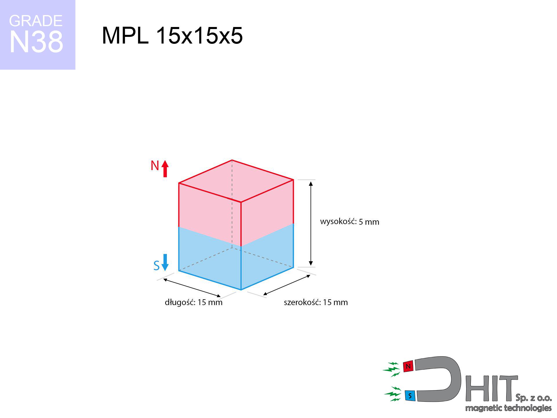
15 mm [±0,1 mm]
Width
15 mm [±0,1 mm]
Height
5 mm [±0,1 mm]
Weight
8.44 g
Magnetization Direction
↑ axial
Load capacity
5.87 kg / 57.62 N
Magnetic Induction
318.00 mT / 3180 Gs
Coating
[NiCuNi] Nickel
4.03 ZŁ with VAT / pcs + price for transport
3.28 ZŁ net + 23% VAT / pcs
bulk discounts:
Need more?
Contact us by phone
+48 22 499 98 98
alternatively contact us using
contact form
the contact page.
Parameters as well as structure of magnets can be tested using our
modular calculator.
Same-day shipping for orders placed before 14:00.
Technical - MPL 15x15x5 / N38 - lamellar magnet
Specification / characteristics - MPL 15x15x5 / N38 - lamellar magnet
| properties | values |
|---|---|
| Cat. no. | 020120 |
| GTIN/EAN | 5906301811268 |
| Production/Distribution | Dhit sp. z o.o. |
| Country of origin | Poland / China / Germany |
| Customs code | 85059029 |
| length | 15 mm [±0,1 mm] |
| Width | 15 mm [±0,1 mm] |
| Height | 5 mm [±0,1 mm] |
| Weight | 8.44 g |
| Magnetization Direction | ↑ axial |
| Load capacity ~ ? | 5.87 kg / 57.62 N |
| Magnetic Induction ~ ? | 318.00 mT / 3180 Gs |
| Coating | [NiCuNi] Nickel |
| Manufacturing Tolerance | ±0.1 mm |
Magnetic properties of material N38
| properties | values | units |
|---|---|---|
| remenance Br [min. - max.] ? | 12.2-12.6 | kGs |
| remenance Br [min. - max.] ? | 1220-1260 | mT |
| coercivity bHc ? | 10.8-11.5 | kOe |
| coercivity bHc ? | 860-915 | kA/m |
| actual internal force iHc | ≥ 12 | kOe |
| actual internal force iHc | ≥ 955 | kA/m |
| energy density [min. - max.] ? | 36-38 | BH max MGOe |
| energy density [min. - max.] ? | 287-303 | BH max KJ/m |
| max. temperature ? | ≤ 80 | °C |
Physical properties of sintered neodymium magnets Nd2Fe14B at 20°C
| properties | values | units |
|---|---|---|
| Vickers hardness | ≥550 | Hv |
| Density | ≥7.4 | g/cm3 |
| Curie Temperature TC | 312 - 380 | °C |
| Curie Temperature TF | 593 - 716 | °F |
| Specific resistance | 150 | μΩ⋅cm |
| Bending strength | 250 | MPa |
| Compressive strength | 1000~1100 | MPa |
| Thermal expansion parallel (∥) to orientation (M) | (3-4) x 10-6 | °C-1 |
| Thermal expansion perpendicular (⊥) to orientation (M) | -(1-3) x 10-6 | °C-1 |
| Young's modulus | 1.7 x 10⁴ | kg/mm² |
Physical modeling of the assembly - technical parameters
The following values constitute the result of a engineering calculation. Results rely on algorithms for the material Nd2Fe14B. Operational performance might slightly differ from theoretical values. Use these calculations as a reference point when designing systems.
Table 1: Static force (force vs gap) - power drop
MPL 15x15x5 / N38
| Distance (mm) | Induction (Gauss) / mT | Pull Force (kg/lbs/g/N) | Risk Status |
|---|---|---|---|
| 0 mm |
3179 Gs
317.9 mT
|
5.87 kg / 12.94 lbs
5870.0 g / 57.6 N
|
warning |
| 1 mm |
2873 Gs
287.3 mT
|
4.79 kg / 10.57 lbs
4794.1 g / 47.0 N
|
warning |
| 2 mm |
2528 Gs
252.8 mT
|
3.71 kg / 8.18 lbs
3712.5 g / 36.4 N
|
warning |
| 3 mm |
2181 Gs
218.1 mT
|
2.76 kg / 6.09 lbs
2763.0 g / 27.1 N
|
warning |
| 5 mm |
1565 Gs
156.5 mT
|
1.42 kg / 3.14 lbs
1422.0 g / 13.9 N
|
low risk |
| 10 mm |
659 Gs
65.9 mT
|
0.25 kg / 0.56 lbs
252.1 g / 2.5 N
|
low risk |
| 15 mm |
307 Gs
30.7 mT
|
0.05 kg / 0.12 lbs
54.7 g / 0.5 N
|
low risk |
| 20 mm |
162 Gs
16.2 mT
|
0.02 kg / 0.03 lbs
15.2 g / 0.1 N
|
low risk |
| 30 mm |
59 Gs
5.9 mT
|
0.00 kg / 0.00 lbs
2.0 g / 0.0 N
|
low risk |
| 50 mm |
15 Gs
1.5 mT
|
0.00 kg / 0.00 lbs
0.1 g / 0.0 N
|
low risk |
Table 2: Sliding load (vertical surface)
MPL 15x15x5 / N38
| Distance (mm) | Friction coefficient | Pull Force (kg/lbs/g/N) |
|---|---|---|
| 0 mm | Stal (~0.2) |
1.17 kg / 2.59 lbs
1174.0 g / 11.5 N
|
| 1 mm | Stal (~0.2) |
0.96 kg / 2.11 lbs
958.0 g / 9.4 N
|
| 2 mm | Stal (~0.2) |
0.74 kg / 1.64 lbs
742.0 g / 7.3 N
|
| 3 mm | Stal (~0.2) |
0.55 kg / 1.22 lbs
552.0 g / 5.4 N
|
| 5 mm | Stal (~0.2) |
0.28 kg / 0.63 lbs
284.0 g / 2.8 N
|
| 10 mm | Stal (~0.2) |
0.05 kg / 0.11 lbs
50.0 g / 0.5 N
|
| 15 mm | Stal (~0.2) |
0.01 kg / 0.02 lbs
10.0 g / 0.1 N
|
| 20 mm | Stal (~0.2) |
0.00 kg / 0.01 lbs
4.0 g / 0.0 N
|
| 30 mm | Stal (~0.2) |
0.00 kg / 0.00 lbs
0.0 g / 0.0 N
|
| 50 mm | Stal (~0.2) |
0.00 kg / 0.00 lbs
0.0 g / 0.0 N
|
Table 3: Vertical assembly (shearing) - behavior on slippery surfaces
MPL 15x15x5 / N38
| Surface type | Friction coefficient / % Mocy | Max load (kg/lbs/g/N) |
|---|---|---|
| Raw steel |
µ = 0.3
30% Nominalnej Siły
|
1.76 kg / 3.88 lbs
1761.0 g / 17.3 N
|
| Painted steel (standard) |
µ = 0.2
20% Nominalnej Siły
|
1.17 kg / 2.59 lbs
1174.0 g / 11.5 N
|
| Oily/slippery steel |
µ = 0.1
10% Nominalnej Siły
|
0.59 kg / 1.29 lbs
587.0 g / 5.8 N
|
| Magnet with anti-slip rubber |
µ = 0.5
50% Nominalnej Siły
|
2.94 kg / 6.47 lbs
2935.0 g / 28.8 N
|
Table 4: Steel thickness (substrate influence) - sheet metal selection
MPL 15x15x5 / N38
| Steel thickness (mm) | % power | Real pull force (kg/lbs/g/N) |
|---|---|---|
| 0.5 mm |
|
0.59 kg / 1.29 lbs
587.0 g / 5.8 N
|
| 1 mm |
|
1.47 kg / 3.24 lbs
1467.5 g / 14.4 N
|
| 2 mm |
|
2.94 kg / 6.47 lbs
2935.0 g / 28.8 N
|
| 3 mm |
|
4.40 kg / 9.71 lbs
4402.5 g / 43.2 N
|
| 5 mm |
|
5.87 kg / 12.94 lbs
5870.0 g / 57.6 N
|
| 10 mm |
|
5.87 kg / 12.94 lbs
5870.0 g / 57.6 N
|
| 11 mm |
|
5.87 kg / 12.94 lbs
5870.0 g / 57.6 N
|
| 12 mm |
|
5.87 kg / 12.94 lbs
5870.0 g / 57.6 N
|
Table 5: Working in heat (material behavior) - power drop
MPL 15x15x5 / N38
| Ambient temp. (°C) | Power loss | Remaining pull (kg/lbs/g/N) | Status |
|---|---|---|---|
| 20 °C | 0.0% |
5.87 kg / 12.94 lbs
5870.0 g / 57.6 N
|
OK |
| 40 °C | -2.2% |
5.74 kg / 12.66 lbs
5740.9 g / 56.3 N
|
OK |
| 60 °C | -4.4% |
5.61 kg / 12.37 lbs
5611.7 g / 55.1 N
|
|
| 80 °C | -6.6% |
5.48 kg / 12.09 lbs
5482.6 g / 53.8 N
|
|
| 100 °C | -28.8% |
4.18 kg / 9.21 lbs
4179.4 g / 41.0 N
|
Table 6: Two magnets (repulsion) - forces in the system
MPL 15x15x5 / N38
| Gap (mm) | Attraction (kg/lbs) (N-S) | Shear Strength (kg/lbs/g/N) | Repulsion (kg/lbs) (N-N) |
|---|---|---|---|
| 0 mm |
14.02 kg / 30.90 lbs
4 741 Gs
|
2.10 kg / 4.64 lbs
2103 g / 20.6 N
|
N/A |
| 1 mm |
12.77 kg / 28.15 lbs
6 068 Gs
|
1.92 kg / 4.22 lbs
1916 g / 18.8 N
|
11.49 kg / 25.34 lbs
~0 Gs
|
| 2 mm |
11.45 kg / 25.24 lbs
5 746 Gs
|
1.72 kg / 3.79 lbs
1717 g / 16.8 N
|
10.30 kg / 22.72 lbs
~0 Gs
|
| 3 mm |
10.13 kg / 22.34 lbs
5 405 Gs
|
1.52 kg / 3.35 lbs
1520 g / 14.9 N
|
9.12 kg / 20.10 lbs
~0 Gs
|
| 5 mm |
7.68 kg / 16.93 lbs
4 706 Gs
|
1.15 kg / 2.54 lbs
1152 g / 11.3 N
|
6.91 kg / 15.24 lbs
~0 Gs
|
| 10 mm |
3.40 kg / 7.49 lbs
3 129 Gs
|
0.51 kg / 1.12 lbs
509 g / 5.0 N
|
3.06 kg / 6.74 lbs
~0 Gs
|
| 20 mm |
0.60 kg / 1.33 lbs
1 318 Gs
|
0.09 kg / 0.20 lbs
90 g / 0.9 N
|
0.54 kg / 1.19 lbs
~0 Gs
|
| 50 mm |
0.01 kg / 0.03 lbs
188 Gs
|
0.00 kg / 0.00 lbs
2 g / 0.0 N
|
0.01 kg / 0.02 lbs
~0 Gs
|
| 60 mm |
0.00 kg / 0.01 lbs
118 Gs
|
0.00 kg / 0.00 lbs
1 g / 0.0 N
|
0.00 kg / 0.00 lbs
~0 Gs
|
| 70 mm |
0.00 kg / 0.00 lbs
79 Gs
|
0.00 kg / 0.00 lbs
0 g / 0.0 N
|
0.00 kg / 0.00 lbs
~0 Gs
|
| 80 mm |
0.00 kg / 0.00 lbs
55 Gs
|
0.00 kg / 0.00 lbs
0 g / 0.0 N
|
0.00 kg / 0.00 lbs
~0 Gs
|
| 90 mm |
0.00 kg / 0.00 lbs
40 Gs
|
0.00 kg / 0.00 lbs
0 g / 0.0 N
|
0.00 kg / 0.00 lbs
~0 Gs
|
| 100 mm |
0.00 kg / 0.00 lbs
30 Gs
|
0.00 kg / 0.00 lbs
0 g / 0.0 N
|
0.00 kg / 0.00 lbs
~0 Gs
|
Table 7: Protective zones (implants) - warnings
MPL 15x15x5 / N38
| Object / Device | Limit (Gauss) / mT | Safe distance |
|---|---|---|
| Pacemaker | 5 Gs (0.5 mT) | 7.5 cm |
| Hearing aid | 10 Gs (1.0 mT) | 6.0 cm |
| Mechanical watch | 20 Gs (2.0 mT) | 4.5 cm |
| Phone / Smartphone | 40 Gs (4.0 mT) | 3.5 cm |
| Remote | 50 Gs (5.0 mT) | 3.5 cm |
| Payment card | 400 Gs (40.0 mT) | 1.5 cm |
| HDD hard drive | 600 Gs (60.0 mT) | 1.5 cm |
Table 8: Dynamics (cracking risk) - collision effects
MPL 15x15x5 / N38
| Start from (mm) | Speed (km/h) | Energy (J) | Predicted outcome |
|---|---|---|---|
| 10 mm |
27.30 km/h
(7.58 m/s)
|
0.24 J | |
| 30 mm |
46.08 km/h
(12.80 m/s)
|
0.69 J | |
| 50 mm |
59.47 km/h
(16.52 m/s)
|
1.15 J | |
| 100 mm |
84.11 km/h
(23.36 m/s)
|
2.30 J |
Table 9: Corrosion resistance
MPL 15x15x5 / N38
| Technical parameter | Value / Description |
|---|---|
| Coating type | [NiCuNi] Nickel |
| Layer structure | Nickel - Copper - Nickel |
| Layer thickness | 10-20 µm |
| Salt spray test (SST) ? | 24 h |
| Recommended environment | Indoors only (dry) |
Table 10: Electrical data (Flux)
MPL 15x15x5 / N38
| Parameter | Value | SI Unit / Description |
|---|---|---|
| Magnetic Flux | 7 651 Mx | 76.5 µWb |
| Pc Coefficient | 0.40 | Low (Flat) |
Table 11: Hydrostatics and buoyancy
MPL 15x15x5 / N38
| Environment | Effective steel pull | Effect |
|---|---|---|
| Air (land) | 5.87 kg | Standard |
| Water (riverbed) |
6.72 kg
(+0.85 kg buoyancy gain)
|
+14.5% |
1. Vertical hold
*Caution: On a vertical wall, the magnet holds only approx. 20-30% of its nominal pull.
2. Plate thickness effect
*Thin metal sheet (e.g. 0.5mm PC case) drastically reduces the holding force.
3. Power loss vs temp
*For N38 material, the safety limit is 80°C.
4. Demagnetization curve and operating point (B-H)
chart generated for the permeance coefficient Pc (Permeance Coefficient) = 0.40
The chart above illustrates the magnetic characteristics of the material within the second quadrant of the hysteresis loop. The solid red line represents the demagnetization curve (material potential), while the dashed blue line is the load line based on the magnet's geometry. The Pc (Permeance Coefficient), also known as the load line slope, is a dimensionless value that describes the relationship between the magnet's shape and its magnetic stability. The intersection of these two lines (the black dot) is the operating point — it determines the actual magnetic flux density generated by the magnet in this specific configuration. A higher Pc value means the magnet is more 'slender' (tall relative to its area), resulting in a higher operating point and better resistance to irreversible demagnetization caused by external fields or temperature. A value of 0.42 is relatively low (typical for flat magnets), meaning the operating point is closer to the 'knee' of the curve — caution is advised when operating at temperatures near the maximum limit to avoid strength loss.
Chemical composition
| iron (Fe) | 64% – 68% |
| neodymium (Nd) | 29% – 32% |
| boron (B) | 1.1% – 1.2% |
| dysprosium (Dy) | 0.5% – 2.0% |
| coating (Ni-Cu-Ni) | < 0.05% |
Sustainability
| recyclability (EoL) | 100% |
| recycled raw materials | ~10% (pre-cons) |
| carbon footprint | low / zredukowany |
| waste code (EWC) | 16 02 16 |
Other proposals


Strengths and weaknesses of neodymium magnets.
Benefits
- They virtually do not lose strength, because even after 10 years the performance loss is only ~1% (based on calculations),
- Magnets perfectly protect themselves against loss of magnetization caused by ambient magnetic noise,
- Thanks to the reflective finish, the coating of Ni-Cu-Ni, gold-plated, or silver-plated gives an elegant appearance,
- The surface of neodymium magnets generates a strong magnetic field – this is a key feature,
- Due to their durability and thermal resistance, neodymium magnets can operate (depending on the form) even at high temperatures reaching 230°C or more...
- Thanks to freedom in forming and the capacity to customize to specific needs,
- Fundamental importance in innovative solutions – they serve a role in magnetic memories, brushless drives, advanced medical instruments, also modern systems.
- Compactness – despite small sizes they offer powerful magnetic field, making them ideal for precision applications
Limitations
- Susceptibility to cracking is one of their disadvantages. Upon intense impact they can break. We advise keeping them in a steel housing, which not only protects them against impacts but also raises their durability
- We warn that neodymium magnets can lose their power at high temperatures. To prevent this, we recommend our specialized [AH] magnets, which work effectively even at 230°C.
- Due to the susceptibility of magnets to corrosion in a humid environment, we recommend using waterproof magnets made of rubber, plastic or other material resistant to moisture, when using outdoors
- Due to limitations in realizing nuts and complicated shapes in magnets, we recommend using a housing - magnetic holder.
- Possible danger to health – tiny shards of magnets can be dangerous, if swallowed, which is particularly important in the aspect of protecting the youngest. Additionally, tiny parts of these magnets are able to disrupt the diagnostic process medical when they are in the body.
- Due to expensive raw materials, their price exceeds standard values,
Pull force analysis
Maximum holding power of the magnet – what it depends on?
- with the contact of a yoke made of special test steel, guaranteeing maximum field concentration
- whose transverse dimension is min. 10 mm
- with an polished touching surface
- under conditions of no distance (metal-to-metal)
- under vertical application of breakaway force (90-degree angle)
- at temperature approx. 20 degrees Celsius
Determinants of lifting force in real conditions
- Distance – the presence of foreign body (rust, dirt, air) acts as an insulator, which reduces power rapidly (even by 50% at 0.5 mm).
- Force direction – remember that the magnet holds strongest perpendicularly. Under shear forces, the holding force drops drastically, often to levels of 20-30% of the maximum value.
- Element thickness – to utilize 100% power, the steel must be adequately massive. Paper-thin metal limits the lifting capacity (the magnet "punches through" it).
- Metal type – different alloys reacts the same. High carbon content weaken the attraction effect.
- Surface condition – ground elements guarantee perfect abutment, which increases force. Uneven metal reduce efficiency.
- Temperature – heating the magnet results in weakening of induction. It is worth remembering the thermal limit for a given model.
Holding force was checked on the plate surface of 20 mm thickness, when a perpendicular force was applied, in contrast under shearing force the lifting capacity is smaller. Moreover, even a minimal clearance between the magnet and the plate lowers the load capacity.
Safe handling of NdFeB magnets
GPS and phone interference
Note: rare earth magnets generate a field that disrupts precision electronics. Maintain a separation from your phone, device, and GPS.
Life threat
For implant holders: Strong magnetic fields affect electronics. Keep at least 30 cm distance or ask another person to handle the magnets.
Handling rules
Before use, check safety instructions. Uncontrolled attraction can break the magnet or injure your hand. Think ahead.
Allergic reactions
Nickel alert: The Ni-Cu-Ni coating consists of nickel. If skin irritation happens, cease handling magnets and use protective gear.
Electronic hazard
Do not bring magnets close to a wallet, computer, or TV. The magnetic field can irreversibly ruin these devices and erase data from cards.
Flammability
Powder generated during grinding of magnets is combustible. Do not drill into magnets without proper cooling and knowledge.
Material brittleness
Watch out for shards. Magnets can fracture upon violent connection, ejecting shards into the air. Wear goggles.
Heat sensitivity
Watch the temperature. Exposing the magnet above 80 degrees Celsius will permanently weaken its magnetic structure and strength.
This is not a toy
NdFeB magnets are not suitable for play. Accidental ingestion of multiple magnets can lead to them attracting across intestines, which constitutes a critical condition and necessitates immediate surgery.
Finger safety
Big blocks can crush fingers instantly. Under no circumstances put your hand between two strong magnets.
Tabela kosztu i czasu dostawy
Płatność przed wysyłką:

GLS kurier
Przesyłka będzie u Ciebie za 2-3 dni
14.99 ZŁ

InPost Paczkomaty 24/7
Przesyłka będzie u Ciebie za 1-2 dni
12.30 ZŁ
Płatność przy odbiorze (pobranie):
GLS kurier
Przesyłka będzie u Ciebie za 1-2 dni
23.00 ZŁ
Rate the product
Your rating