
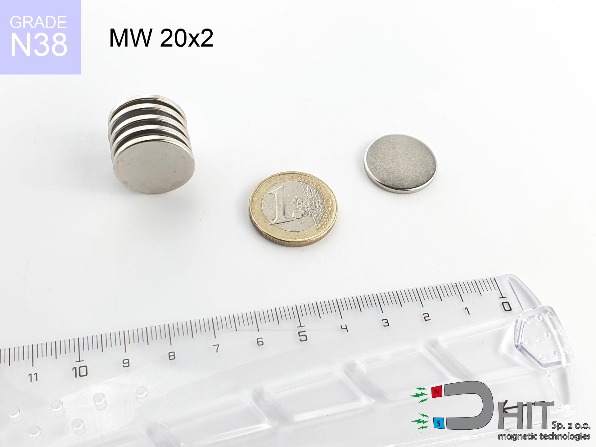
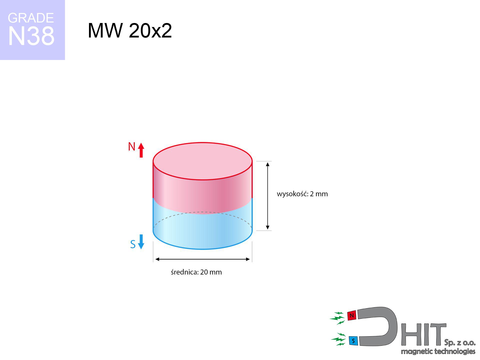
MW 20x2 / N38 - cylindrical magnet
cylindrical magnet
Catalog no 010041
GTIN/EAN: 5906301810407
Diameter Ø
20 mm [±0,1 mm]
Height
2 mm [±0,1 mm]
Weight
4.71 g
Magnetization Direction
↑ axial
Load capacity
1.63 kg / 16.02 N
Magnetic Induction
121.57 mT / 1216 Gs
Coating
[NiCuNi] Nickel
2.08 ZŁ with VAT / pcs + price for transport
1.690 ZŁ net + 23% VAT / pcs
bulk discounts:
Need more?
Pick up the phone and ask
+48 22 499 98 98
or let us know using
contact form
our website.
Strength and form of magnets can be checked using our
modular calculator.
Same-day processing for orders placed before 14:00.
Technical parameters of the product - MW 20x2 / N38 - cylindrical magnet
Specification / characteristics - MW 20x2 / N38 - cylindrical magnet
| properties | values |
|---|---|
| Cat. no. | 010041 |
| GTIN/EAN | 5906301810407 |
| Production/Distribution | Dhit sp. z o.o. |
| Country of origin | Poland / China / Germany |
| Customs code | 85059029 |
| Diameter Ø | 20 mm [±0,1 mm] |
| Height | 2 mm [±0,1 mm] |
| Weight | 4.71 g |
| Magnetization Direction | ↑ axial |
| Load capacity ~ ? | 1.63 kg / 16.02 N |
| Magnetic Induction ~ ? | 121.57 mT / 1216 Gs |
| Coating | [NiCuNi] Nickel |
| Manufacturing Tolerance | ±0.1 mm |
Magnetic properties of material N38
| properties | values | units |
|---|---|---|
| remenance Br [min. - max.] ? | 12.2-12.6 | kGs |
| remenance Br [min. - max.] ? | 1220-1260 | mT |
| coercivity bHc ? | 10.8-11.5 | kOe |
| coercivity bHc ? | 860-915 | kA/m |
| actual internal force iHc | ≥ 12 | kOe |
| actual internal force iHc | ≥ 955 | kA/m |
| energy density [min. - max.] ? | 36-38 | BH max MGOe |
| energy density [min. - max.] ? | 287-303 | BH max KJ/m |
| max. temperature ? | ≤ 80 | °C |
Physical properties of sintered neodymium magnets Nd2Fe14B at 20°C
| properties | values | units |
|---|---|---|
| Vickers hardness | ≥550 | Hv |
| Density | ≥7.4 | g/cm3 |
| Curie Temperature TC | 312 - 380 | °C |
| Curie Temperature TF | 593 - 716 | °F |
| Specific resistance | 150 | μΩ⋅cm |
| Bending strength | 250 | MPa |
| Compressive strength | 1000~1100 | MPa |
| Thermal expansion parallel (∥) to orientation (M) | (3-4) x 10-6 | °C-1 |
| Thermal expansion perpendicular (⊥) to orientation (M) | -(1-3) x 10-6 | °C-1 |
| Young's modulus | 1.7 x 10⁴ | kg/mm² |
Physical analysis of the magnet - report
The following values constitute the direct effect of a mathematical analysis. Results were calculated on models for the class Nd2Fe14B. Real-world conditions may differ from theoretical values. Use these calculations as a supplementary guide when designing systems.
Table 1: Static pull force (force vs gap) - characteristics
MW 20x2 / N38
| Distance (mm) | Induction (Gauss) / mT | Pull Force (kg/lbs/g/N) | Risk Status |
|---|---|---|---|
| 0 mm |
1216 Gs
121.6 mT
|
1.63 kg / 3.59 lbs
1630.0 g / 16.0 N
|
weak grip |
| 1 mm |
1165 Gs
116.5 mT
|
1.50 kg / 3.30 lbs
1496.3 g / 14.7 N
|
weak grip |
| 2 mm |
1087 Gs
108.7 mT
|
1.30 kg / 2.87 lbs
1302.7 g / 12.8 N
|
weak grip |
| 3 mm |
991 Gs
99.1 mT
|
1.08 kg / 2.39 lbs
1083.7 g / 10.6 N
|
weak grip |
| 5 mm |
783 Gs
78.3 mT
|
0.68 kg / 1.49 lbs
675.9 g / 6.6 N
|
weak grip |
| 10 mm |
379 Gs
37.9 mT
|
0.16 kg / 0.35 lbs
158.4 g / 1.6 N
|
weak grip |
| 15 mm |
185 Gs
18.5 mT
|
0.04 kg / 0.08 lbs
37.9 g / 0.4 N
|
weak grip |
| 20 mm |
99 Gs
9.9 mT
|
0.01 kg / 0.02 lbs
10.8 g / 0.1 N
|
weak grip |
| 30 mm |
36 Gs
3.6 mT
|
0.00 kg / 0.00 lbs
1.4 g / 0.0 N
|
weak grip |
| 50 mm |
9 Gs
0.9 mT
|
0.00 kg / 0.00 lbs
0.1 g / 0.0 N
|
weak grip |
Table 2: Vertical hold (vertical surface)
MW 20x2 / N38
| Distance (mm) | Friction coefficient | Pull Force (kg/lbs/g/N) |
|---|---|---|
| 0 mm | Stal (~0.2) |
0.33 kg / 0.72 lbs
326.0 g / 3.2 N
|
| 1 mm | Stal (~0.2) |
0.30 kg / 0.66 lbs
300.0 g / 2.9 N
|
| 2 mm | Stal (~0.2) |
0.26 kg / 0.57 lbs
260.0 g / 2.6 N
|
| 3 mm | Stal (~0.2) |
0.22 kg / 0.48 lbs
216.0 g / 2.1 N
|
| 5 mm | Stal (~0.2) |
0.14 kg / 0.30 lbs
136.0 g / 1.3 N
|
| 10 mm | Stal (~0.2) |
0.03 kg / 0.07 lbs
32.0 g / 0.3 N
|
| 15 mm | Stal (~0.2) |
0.01 kg / 0.02 lbs
8.0 g / 0.1 N
|
| 20 mm | Stal (~0.2) |
0.00 kg / 0.00 lbs
2.0 g / 0.0 N
|
| 30 mm | Stal (~0.2) |
0.00 kg / 0.00 lbs
0.0 g / 0.0 N
|
| 50 mm | Stal (~0.2) |
0.00 kg / 0.00 lbs
0.0 g / 0.0 N
|
Table 3: Vertical assembly (sliding) - vertical pull
MW 20x2 / N38
| Surface type | Friction coefficient / % Mocy | Max load (kg/lbs/g/N) |
|---|---|---|
| Raw steel |
µ = 0.3
30% Nominalnej Siły
|
0.49 kg / 1.08 lbs
489.0 g / 4.8 N
|
| Painted steel (standard) |
µ = 0.2
20% Nominalnej Siły
|
0.33 kg / 0.72 lbs
326.0 g / 3.2 N
|
| Oily/slippery steel |
µ = 0.1
10% Nominalnej Siły
|
0.16 kg / 0.36 lbs
163.0 g / 1.6 N
|
| Magnet with anti-slip rubber |
µ = 0.5
50% Nominalnej Siły
|
0.82 kg / 1.80 lbs
815.0 g / 8.0 N
|
Table 4: Steel thickness (saturation) - sheet metal selection
MW 20x2 / N38
| Steel thickness (mm) | % power | Real pull force (kg/lbs/g/N) |
|---|---|---|
| 0.5 mm |
|
0.16 kg / 0.36 lbs
163.0 g / 1.6 N
|
| 1 mm |
|
0.41 kg / 0.90 lbs
407.5 g / 4.0 N
|
| 2 mm |
|
0.82 kg / 1.80 lbs
815.0 g / 8.0 N
|
| 3 mm |
|
1.22 kg / 2.70 lbs
1222.5 g / 12.0 N
|
| 5 mm |
|
1.63 kg / 3.59 lbs
1630.0 g / 16.0 N
|
| 10 mm |
|
1.63 kg / 3.59 lbs
1630.0 g / 16.0 N
|
| 11 mm |
|
1.63 kg / 3.59 lbs
1630.0 g / 16.0 N
|
| 12 mm |
|
1.63 kg / 3.59 lbs
1630.0 g / 16.0 N
|
Table 5: Thermal resistance (stability) - power drop
MW 20x2 / N38
| Ambient temp. (°C) | Power loss | Remaining pull (kg/lbs/g/N) | Status |
|---|---|---|---|
| 20 °C | 0.0% |
1.63 kg / 3.59 lbs
1630.0 g / 16.0 N
|
OK |
| 40 °C | -2.2% |
1.59 kg / 3.51 lbs
1594.1 g / 15.6 N
|
OK |
| 60 °C | -4.4% |
1.56 kg / 3.44 lbs
1558.3 g / 15.3 N
|
|
| 80 °C | -6.6% |
1.52 kg / 3.36 lbs
1522.4 g / 14.9 N
|
|
| 100 °C | -28.8% |
1.16 kg / 2.56 lbs
1160.6 g / 11.4 N
|
Table 6: Magnet-Magnet interaction (repulsion) - field range
MW 20x2 / N38
| Gap (mm) | Attraction (kg/lbs) (N-S) | Sliding Force (kg/lbs/g/N) | Repulsion (kg/lbs) (N-N) |
|---|---|---|---|
| 0 mm |
2.86 kg / 6.31 lbs
2 301 Gs
|
0.43 kg / 0.95 lbs
429 g / 4.2 N
|
N/A |
| 1 mm |
2.76 kg / 6.09 lbs
2 388 Gs
|
0.41 kg / 0.91 lbs
414 g / 4.1 N
|
2.49 kg / 5.48 lbs
~0 Gs
|
| 2 mm |
2.63 kg / 5.79 lbs
2 329 Gs
|
0.39 kg / 0.87 lbs
394 g / 3.9 N
|
2.36 kg / 5.21 lbs
~0 Gs
|
| 3 mm |
2.47 kg / 5.44 lbs
2 257 Gs
|
0.37 kg / 0.82 lbs
370 g / 3.6 N
|
2.22 kg / 4.89 lbs
~0 Gs
|
| 5 mm |
2.10 kg / 4.62 lbs
2 081 Gs
|
0.31 kg / 0.69 lbs
315 g / 3.1 N
|
1.89 kg / 4.16 lbs
~0 Gs
|
| 10 mm |
1.19 kg / 2.62 lbs
1 565 Gs
|
0.18 kg / 0.39 lbs
178 g / 1.7 N
|
1.07 kg / 2.35 lbs
~0 Gs
|
| 20 mm |
0.28 kg / 0.61 lbs
758 Gs
|
0.04 kg / 0.09 lbs
42 g / 0.4 N
|
0.25 kg / 0.55 lbs
~0 Gs
|
| 50 mm |
0.01 kg / 0.01 lbs
115 Gs
|
0.00 kg / 0.00 lbs
1 g / 0.0 N
|
0.00 kg / 0.00 lbs
~0 Gs
|
| 60 mm |
0.00 kg / 0.01 lbs
72 Gs
|
0.00 kg / 0.00 lbs
0 g / 0.0 N
|
0.00 kg / 0.00 lbs
~0 Gs
|
| 70 mm |
0.00 kg / 0.00 lbs
48 Gs
|
0.00 kg / 0.00 lbs
0 g / 0.0 N
|
0.00 kg / 0.00 lbs
~0 Gs
|
| 80 mm |
0.00 kg / 0.00 lbs
33 Gs
|
0.00 kg / 0.00 lbs
0 g / 0.0 N
|
0.00 kg / 0.00 lbs
~0 Gs
|
| 90 mm |
0.00 kg / 0.00 lbs
24 Gs
|
0.00 kg / 0.00 lbs
0 g / 0.0 N
|
0.00 kg / 0.00 lbs
~0 Gs
|
| 100 mm |
0.00 kg / 0.00 lbs
18 Gs
|
0.00 kg / 0.00 lbs
0 g / 0.0 N
|
0.00 kg / 0.00 lbs
~0 Gs
|
Table 7: Hazards (implants) - precautionary measures
MW 20x2 / N38
| Object / Device | Limit (Gauss) / mT | Safe distance |
|---|---|---|
| Pacemaker | 5 Gs (0.5 mT) | 6.5 cm |
| Hearing aid | 10 Gs (1.0 mT) | 5.0 cm |
| Mechanical watch | 20 Gs (2.0 mT) | 4.0 cm |
| Phone / Smartphone | 40 Gs (4.0 mT) | 3.0 cm |
| Remote | 50 Gs (5.0 mT) | 3.0 cm |
| Payment card | 400 Gs (40.0 mT) | 1.0 cm |
| HDD hard drive | 600 Gs (60.0 mT) | 1.0 cm |
Table 8: Collisions (kinetic energy) - warning
MW 20x2 / N38
| Start from (mm) | Speed (km/h) | Energy (J) | Predicted outcome |
|---|---|---|---|
| 10 mm |
19.87 km/h
(5.52 m/s)
|
0.07 J | |
| 30 mm |
32.51 km/h
(9.03 m/s)
|
0.19 J | |
| 50 mm |
41.95 km/h
(11.65 m/s)
|
0.32 J | |
| 100 mm |
59.33 km/h
(16.48 m/s)
|
0.64 J |
Table 9: Coating parameters (durability)
MW 20x2 / N38
| Technical parameter | Value / Description |
|---|---|
| Coating type | [NiCuNi] Nickel |
| Layer structure | Nickel - Copper - Nickel |
| Layer thickness | 10-20 µm |
| Salt spray test (SST) ? | 24 h |
| Recommended environment | Indoors only (dry) |
Table 10: Electrical data (Pc)
MW 20x2 / N38
| Parameter | Value | SI Unit / Description |
|---|---|---|
| Magnetic Flux | 5 038 Mx | 50.4 µWb |
| Pc Coefficient | 0.16 | Low (Flat) |
Table 11: Underwater work (magnet fishing)
MW 20x2 / N38
| Environment | Effective steel pull | Effect |
|---|---|---|
| Air (land) | 1.63 kg | Standard |
| Water (riverbed) |
1.87 kg
(+0.24 kg buoyancy gain)
|
+14.5% |
1. Shear force
*Note: On a vertical wall, the magnet retains merely ~20% of its nominal pull.
2. Plate thickness effect
*Thin steel (e.g. computer case) significantly weakens the holding force.
3. Thermal stability
*For standard magnets, the max working temp is 80°C.
4. Demagnetization curve and operating point (B-H)
chart generated for the permeance coefficient Pc (Permeance Coefficient) = 0.16
The chart above illustrates the magnetic characteristics of the material within the second quadrant of the hysteresis loop. The solid red line represents the demagnetization curve (material potential), while the dashed blue line is the load line based on the magnet's geometry. The Pc (Permeance Coefficient), also known as the load line slope, is a dimensionless value that describes the relationship between the magnet's shape and its magnetic stability. The intersection of these two lines (the black dot) is the operating point — it determines the actual magnetic flux density generated by the magnet in this specific configuration. A higher Pc value means the magnet is more 'slender' (tall relative to its area), resulting in a higher operating point and better resistance to irreversible demagnetization caused by external fields or temperature. A value of 0.42 is relatively low (typical for flat magnets), meaning the operating point is closer to the 'knee' of the curve — caution is advised when operating at temperatures near the maximum limit to avoid strength loss.
Material specification
| iron (Fe) | 64% – 68% |
| neodymium (Nd) | 29% – 32% |
| boron (B) | 1.1% – 1.2% |
| dysprosium (Dy) | 0.5% – 2.0% |
| coating (Ni-Cu-Ni) | < 0.05% |
Environmental data
| recyclability (EoL) | 100% |
| recycled raw materials | ~10% (pre-cons) |
| carbon footprint | low / zredukowany |
| waste code (EWC) | 16 02 16 |
Other products

![AM ucho małe [M8] - magnetic accessories](https://cdn3.dhit.pl/graphics/products/am-ucho-małe-m8-zud.jpg "AM ucho małe [M8] - magnetic accessories")


Strengths and weaknesses of neodymium magnets.
Strengths
- Their power remains stable, and after approximately ten years it drops only by ~1% (theoretically),
- They have excellent resistance to magnetic field loss when exposed to external magnetic sources,
- Thanks to the glossy finish, the surface of Ni-Cu-Ni, gold, or silver gives an visually attractive appearance,
- They show high magnetic induction at the operating surface, which affects their effectiveness,
- Thanks to resistance to high temperature, they can operate (depending on the form) even at temperatures up to 230°C and higher...
- Possibility of exact shaping and optimizing to individual needs,
- Key role in modern industrial fields – they are commonly used in data components, drive modules, medical equipment, also technologically advanced constructions.
- Thanks to their power density, small magnets offer high operating force, occupying minimum space,
Limitations
- To avoid cracks upon strong impacts, we suggest using special steel holders. Such a solution protects the magnet and simultaneously improves its durability.
- Neodymium magnets lose their power under the influence of heating. As soon as 80°C is exceeded, many of them start losing their force. Therefore, we recommend our special magnets marked [AH], which maintain stability even at temperatures up to 230°C
- Due to the susceptibility of magnets to corrosion in a humid environment, we suggest using waterproof magnets made of rubber, plastic or other material stable to moisture, in case of application outdoors
- Limited possibility of producing threads in the magnet and complex forms - recommended is a housing - magnetic holder.
- Potential hazard resulting from small fragments of magnets pose a threat, in case of ingestion, which gains importance in the context of child safety. Additionally, tiny parts of these devices can complicate diagnosis medical in case of swallowing.
- High unit price – neodymium magnets have a higher price than other types of magnets (e.g. ferrite), which hinders application in large quantities
Pull force analysis
Maximum lifting force for a neodymium magnet – what affects it?
- on a plate made of mild steel, optimally conducting the magnetic flux
- possessing a thickness of at least 10 mm to avoid saturation
- characterized by lack of roughness
- without any air gap between the magnet and steel
- during pulling in a direction vertical to the plane
- in neutral thermal conditions
Lifting capacity in practice – influencing factors
- Distance – the presence of foreign body (rust, dirt, gap) interrupts the magnetic circuit, which lowers power steeply (even by 50% at 0.5 mm).
- Force direction – catalog parameter refers to detachment vertically. When slipping, the magnet holds significantly lower power (often approx. 20-30% of nominal force).
- Wall thickness – the thinner the sheet, the weaker the hold. Magnetic flux penetrates through instead of generating force.
- Material composition – not every steel reacts the same. High carbon content worsen the interaction with the magnet.
- Plate texture – smooth surfaces ensure maximum contact, which increases force. Uneven metal reduce efficiency.
- Heat – neodymium magnets have a negative temperature coefficient. When it is hot they are weaker, and at low temperatures they can be stronger (up to a certain limit).
Lifting capacity testing was carried out on a smooth plate of optimal thickness, under a perpendicular pulling force, however under attempts to slide the magnet the lifting capacity is smaller. Moreover, even a minimal clearance between the magnet and the plate decreases the load capacity.
Precautions when working with neodymium magnets
Physical harm
Risk of injury: The attraction force is so immense that it can cause blood blisters, pinching, and broken bones. Use thick gloves.
Operating temperature
Keep cool. Neodymium magnets are susceptible to temperature. If you need operation above 80°C, inquire about special high-temperature series (H, SH, UH).
Swallowing risk
Only for adults. Small elements can be swallowed, causing severe trauma. Store away from kids and pets.
Conscious usage
Before starting, read the rules. Uncontrolled attraction can break the magnet or hurt your hand. Think ahead.
Dust is flammable
Dust produced during machining of magnets is combustible. Do not drill into magnets without proper cooling and knowledge.
Eye protection
Watch out for shards. Magnets can fracture upon uncontrolled impact, launching sharp fragments into the air. We recommend safety glasses.
Compass and GPS
A powerful magnetic field interferes with the operation of compasses in smartphones and GPS navigation. Keep magnets close to a device to avoid damaging the sensors.
Cards and drives
Do not bring magnets near a wallet, laptop, or screen. The magnetic field can irreversibly ruin these devices and erase data from cards.
Warning for allergy sufferers
Warning for allergy sufferers: The Ni-Cu-Ni coating contains nickel. If redness happens, immediately stop working with magnets and use protective gear.
Medical interference
For implant holders: Strong magnetic fields disrupt electronics. Maintain at least 30 cm distance or request help to work with the magnets.
Tabela kosztu i czasu dostawy
Płatność przed wysyłką:

GLS kurier
Przesyłka będzie u Ciebie za 2-3 dni
14.99 ZŁ

InPost Paczkomaty 24/7
Przesyłka będzie u Ciebie za 1-2 dni
12.30 ZŁ
Płatność przy odbiorze (pobranie):
GLS kurier
Przesyłka będzie u Ciebie za 1-2 dni
23.00 ZŁ
Rate the product
Your rating