

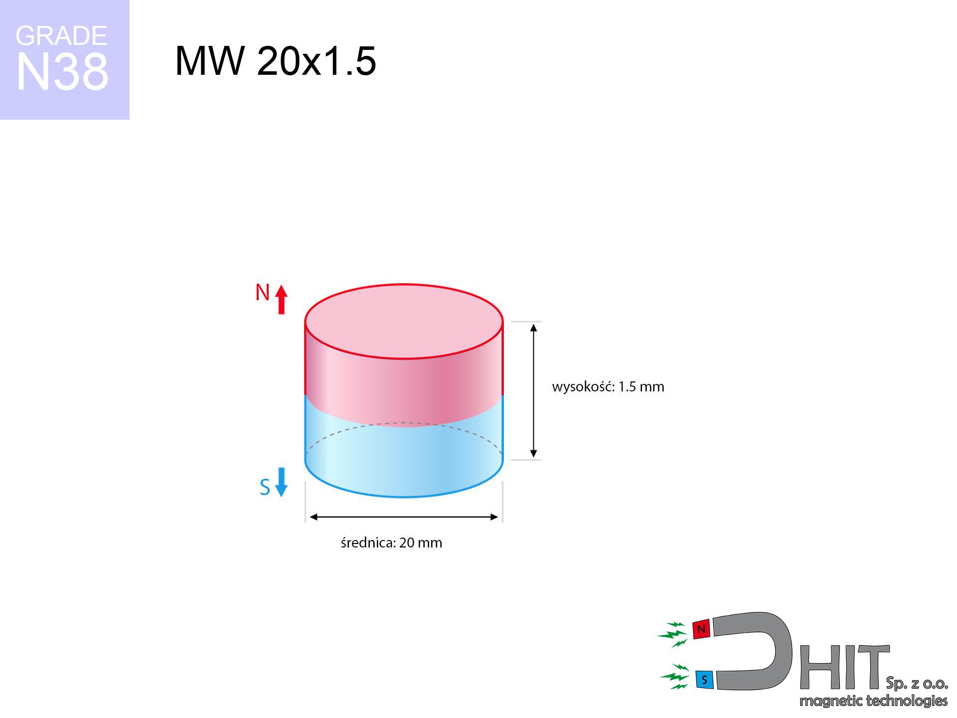
MW 20x1.5 / N38 - cylindrical magnet
cylindrical magnet
Catalog no 010039
GTIN/EAN: 5906301810384
Diameter Ø
20 mm [±0,1 mm]
Height
1.5 mm [±0,1 mm]
Weight
3.53 g
Magnetization Direction
↑ axial
Load capacity
0.97 kg / 9.50 N
Magnetic Induction
91.96 mT / 920 Gs
Coating
[NiCuNi] Nickel
1.574 ZŁ with VAT / pcs + price for transport
1.280 ZŁ net + 23% VAT / pcs
bulk discounts:
Need more?Engineering report for this magnet
Full PDF analysis: pull and shear force, effect of distance, temperature and plate thickness, safety distances and the demagnetization curve.
Contact us by phone
+48 888 99 98 98
alternatively let us know by means of
form
through our site.
Lifting power along with appearance of neodymium magnets can be verified on our
online calculation tool.
Orders submitted before 14:00 will be dispatched today!
Physical properties - MW 20x1.5 / N38 - cylindrical magnet
Specification / characteristics - MW 20x1.5 / N38 - cylindrical magnet
| properties | values |
|---|---|
| Cat. no. | 010039 |
| GTIN/EAN | 5906301810384 |
| Production/Distribution | Dhit sp. z o.o. |
| Country of origin | Poland / China / Germany |
| Customs code | 85059029 |
| Diameter Ø | 20 mm [±0,1 mm] |
| Height | 1.5 mm [±0,1 mm] |
| Weight | 3.53 g |
| Magnetization Direction | ↑ axial |
| Load capacity ~ ? | 0.97 kg / 9.50 N |
| Magnetic Induction ~ ? | 91.96 mT / 920 Gs |
| Coating | [NiCuNi] Nickel |
| Manufacturing Tolerance | ±0.1 mm |
Magnetic properties of material N38
| properties | values | units |
|---|---|---|
| remenance Br [min. - max.] ? | 12.2-12.6 | kGs |
| remenance Br [min. - max.] ? | 1220-1260 | mT |
| coercivity bHc ? | 10.8-11.5 | kOe |
| coercivity bHc ? | 860-915 | kA/m |
| actual internal force iHc | ≥ 12 | kOe |
| actual internal force iHc | ≥ 955 | kA/m |
| energy density [min. - max.] ? | 36-38 | BH max MGOe |
| energy density [min. - max.] ? | 287-303 | BH max KJ/m |
| max. temperature ? | ≤ 80 | °C |
Physical properties of sintered neodymium magnets Nd2Fe14B at 20°C
| properties | values | units |
|---|---|---|
| Vickers hardness | ≥550 | Hv |
| Density | ≥7.4 | g/cm3 |
| Curie Temperature TC | 312 - 380 | °C |
| Curie Temperature TF | 593 - 716 | °F |
| Specific resistance | 150 | μΩ⋅cm |
| Bending strength | 250 | MPa |
| Compressive strength | 1000~1100 | MPa |
| Thermal expansion parallel (∥) to orientation (M) | (3-4) x 10-6 | °C-1 |
| Thermal expansion perpendicular (⊥) to orientation (M) | -(1-3) x 10-6 | °C-1 |
| Young's modulus | 1.7 x 10⁴ | kg/mm² |
Technical modeling of the product - data
The following information are the outcome of a mathematical analysis. Results are based on models for the class Nd2Fe14B. Operational parameters may deviate from the simulation results. Please consider these calculations as a preliminary roadmap when designing systems.
Table 1: Static force (pull vs gap) - interaction chart
MW 20x1.5 / N38
| Distance (mm) | Induction (Gauss) / mT | Pull Force (kg/lbs/g/N) | Risk Status |
|---|---|---|---|
| 0 mm |
920 Gs
92.0 mT
|
0.97 kg / 2.14 LBS
970.0 g / 9.5 N
|
safe |
| 1 mm |
887 Gs
88.7 mT
|
0.90 kg / 1.99 LBS
902.2 g / 8.9 N
|
safe |
| 2 mm |
832 Gs
83.2 mT
|
0.79 kg / 1.75 LBS
794.6 g / 7.8 N
|
safe |
| 3 mm |
763 Gs
76.3 mT
|
0.67 kg / 1.47 LBS
667.4 g / 6.5 N
|
safe |
| 5 mm |
606 Gs
60.6 mT
|
0.42 kg / 0.93 LBS
421.6 g / 4.1 N
|
safe |
| 10 mm |
294 Gs
29.4 mT
|
0.10 kg / 0.22 LBS
99.5 g / 1.0 N
|
safe |
| 15 mm |
144 Gs
14.4 mT
|
0.02 kg / 0.05 LBS
23.6 g / 0.2 N
|
safe |
| 20 mm |
76 Gs
7.6 mT
|
0.01 kg / 0.01 LBS
6.7 g / 0.1 N
|
safe |
| 30 mm |
28 Gs
2.8 mT
|
0.00 kg / 0.00 LBS
0.9 g / 0.0 N
|
safe |
| 50 mm |
7 Gs
0.7 mT
|
0.00 kg / 0.00 LBS
0.1 g / 0.0 N
|
safe |
Table 2: Vertical hold (vertical surface)
MW 20x1.5 / N38
| Distance (mm) | Friction coefficient | Pull Force (kg/lbs/g/N) |
|---|---|---|
| 0 mm | Stal (~0.2) |
0.19 kg / 0.43 LBS
194.0 g / 1.9 N
|
| 1 mm | Stal (~0.2) |
0.18 kg / 0.40 LBS
180.0 g / 1.8 N
|
| 2 mm | Stal (~0.2) |
0.16 kg / 0.35 LBS
158.0 g / 1.5 N
|
| 3 mm | Stal (~0.2) |
0.13 kg / 0.30 LBS
134.0 g / 1.3 N
|
| 5 mm | Stal (~0.2) |
0.08 kg / 0.19 LBS
84.0 g / 0.8 N
|
| 10 mm | Stal (~0.2) |
0.02 kg / 0.04 LBS
20.0 g / 0.2 N
|
| 15 mm | Stal (~0.2) |
0.00 kg / 0.01 LBS
4.0 g / 0.0 N
|
| 20 mm | Stal (~0.2) |
0.00 kg / 0.00 LBS
2.0 g / 0.0 N
|
| 30 mm | Stal (~0.2) |
0.00 kg / 0.00 LBS
0.0 g / 0.0 N
|
| 50 mm | Stal (~0.2) |
0.00 kg / 0.00 LBS
0.0 g / 0.0 N
|
Table 3: Wall mounting (sliding) - vertical pull
MW 20x1.5 / N38
| Surface type | Friction coefficient / % Mocy | Max load (kg/lbs/g/N) |
|---|---|---|
| Raw steel |
µ = 0.3
30% Nominalnej Siły
|
0.29 kg / 0.64 LBS
291.0 g / 2.9 N
|
| Painted steel (standard) |
µ = 0.2
20% Nominalnej Siły
|
0.19 kg / 0.43 LBS
194.0 g / 1.9 N
|
| Oily/slippery steel |
µ = 0.1
10% Nominalnej Siły
|
0.10 kg / 0.21 LBS
97.0 g / 1.0 N
|
| Magnet with anti-slip rubber |
µ = 0.5
50% Nominalnej Siły
|
0.49 kg / 1.07 LBS
485.0 g / 4.8 N
|
Table 4: Steel thickness (substrate influence) - sheet metal selection
MW 20x1.5 / N38
| Steel thickness (mm) | % power | Real pull force (kg/lbs/g/N) |
|---|---|---|
| 0.5 mm |
|
0.10 kg / 0.21 LBS
97.0 g / 1.0 N
|
| 1 mm |
|
0.24 kg / 0.53 LBS
242.5 g / 2.4 N
|
| 2 mm |
|
0.49 kg / 1.07 LBS
485.0 g / 4.8 N
|
| 3 mm |
|
0.73 kg / 1.60 LBS
727.5 g / 7.1 N
|
| 5 mm |
|
0.97 kg / 2.14 LBS
970.0 g / 9.5 N
|
| 10 mm |
|
0.97 kg / 2.14 LBS
970.0 g / 9.5 N
|
| 11 mm |
|
0.97 kg / 2.14 LBS
970.0 g / 9.5 N
|
| 12 mm |
|
0.97 kg / 2.14 LBS
970.0 g / 9.5 N
|
Table 5: Thermal resistance (stability) - thermal limit
MW 20x1.5 / N38
| Ambient temp. (°C) | Power loss | Remaining pull (kg/lbs/g/N) | Status |
|---|---|---|---|
| 20 °C | 0.0% |
0.97 kg / 2.14 LBS
970.0 g / 9.5 N
|
OK |
| 40 °C | -2.2% |
0.95 kg / 2.09 LBS
948.7 g / 9.3 N
|
OK |
| 60 °C | -4.4% |
0.93 kg / 2.04 LBS
927.3 g / 9.1 N
|
|
| 80 °C | -6.6% |
0.91 kg / 2.00 LBS
906.0 g / 8.9 N
|
|
| 100 °C | -28.8% |
0.69 kg / 1.52 LBS
690.6 g / 6.8 N
|
Table 6: Magnet-Magnet interaction (attraction) - forces in the system
MW 20x1.5 / N38
| Gap (mm) | Attraction (kg/lbs) (N-S) | Shear Strength (kg/lbs/g/N) | Repulsion (kg/lbs) (N-N) |
|---|---|---|---|
| 0 mm |
1.64 kg / 3.61 LBS
1 781 Gs
|
0.25 kg / 0.54 LBS
246 g / 2.4 N
|
N/A |
| 1 mm |
1.59 kg / 3.51 LBS
1 813 Gs
|
0.24 kg / 0.53 LBS
239 g / 2.3 N
|
1.43 kg / 3.16 LBS
~0 Gs
|
| 2 mm |
1.52 kg / 3.36 LBS
1 774 Gs
|
0.23 kg / 0.50 LBS
228 g / 2.2 N
|
1.37 kg / 3.02 LBS
~0 Gs
|
| 3 mm |
1.44 kg / 3.17 LBS
1 724 Gs
|
0.22 kg / 0.48 LBS
216 g / 2.1 N
|
1.29 kg / 2.85 LBS
~0 Gs
|
| 5 mm |
1.24 kg / 2.73 LBS
1 598 Gs
|
0.19 kg / 0.41 LBS
185 g / 1.8 N
|
1.11 kg / 2.45 LBS
~0 Gs
|
| 10 mm |
0.71 kg / 1.57 LBS
1 212 Gs
|
0.11 kg / 0.24 LBS
107 g / 1.0 N
|
0.64 kg / 1.41 LBS
~0 Gs
|
| 20 mm |
0.17 kg / 0.37 LBS
589 Gs
|
0.03 kg / 0.06 LBS
25 g / 0.2 N
|
0.15 kg / 0.33 LBS
~0 Gs
|
| 50 mm |
0.00 kg / 0.01 LBS
88 Gs
|
0.00 kg / 0.00 LBS
1 g / 0.0 N
|
0.00 kg / 0.00 LBS
~0 Gs
|
| 60 mm |
0.00 kg / 0.00 LBS
55 Gs
|
0.00 kg / 0.00 LBS
0 g / 0.0 N
|
0.00 kg / 0.00 LBS
~0 Gs
|
| 70 mm |
0.00 kg / 0.00 LBS
36 Gs
|
0.00 kg / 0.00 LBS
0 g / 0.0 N
|
0.00 kg / 0.00 LBS
~0 Gs
|
| 80 mm |
0.00 kg / 0.00 LBS
25 Gs
|
0.00 kg / 0.00 LBS
0 g / 0.0 N
|
0.00 kg / 0.00 LBS
~0 Gs
|
| 90 mm |
0.00 kg / 0.00 LBS
18 Gs
|
0.00 kg / 0.00 LBS
0 g / 0.0 N
|
0.00 kg / 0.00 LBS
~0 Gs
|
| 100 mm |
0.00 kg / 0.00 LBS
13 Gs
|
0.00 kg / 0.00 LBS
0 g / 0.0 N
|
0.00 kg / 0.00 LBS
~0 Gs
|
Table 7: Protective zones (electronics) - precautionary measures
MW 20x1.5 / N38
| Object / Device | Limit (Gauss) / mT | Safe distance |
|---|---|---|
| Pacemaker | 5 Gs (0.5 mT) | 6.0 cm |
| Hearing aid | 10 Gs (1.0 mT) | 4.5 cm |
| Mechanical watch | 20 Gs (2.0 mT) | 3.5 cm |
| Mobile device | 40 Gs (4.0 mT) | 3.0 cm |
| Remote | 50 Gs (5.0 mT) | 2.5 cm |
| Payment card | 400 Gs (40.0 mT) | 1.0 cm |
| HDD hard drive | 600 Gs (60.0 mT) | 1.0 cm |
Table 8: Dynamics (cracking risk) - warning
MW 20x1.5 / N38
| Start from (mm) | Speed (km/h) | Energy (J) | Predicted outcome |
|---|---|---|---|
| 10 mm |
17.76 km/h
(4.93 m/s)
|
0.04 J | |
| 30 mm |
28.97 km/h
(8.05 m/s)
|
0.11 J | |
| 50 mm |
37.38 km/h
(10.38 m/s)
|
0.19 J | |
| 100 mm |
52.87 km/h
(14.69 m/s)
|
0.38 J |
Table 9: Corrosion resistance
MW 20x1.5 / N38
| Technical parameter | Value / Description |
|---|---|
| Coating type | [NiCuNi] Nickel |
| Layer structure | Nickel - Copper - Nickel |
| Layer thickness | 10-20 µm |
| Salt spray test (SST) ? | 24 h |
| Recommended environment | Indoors only (dry) |
Table 10: Electrical data (Pc)
MW 20x1.5 / N38
| Parameter | Value | SI Unit / Description |
|---|---|---|
| Magnetic Flux | 3 979 Mx | 39.8 µWb |
| Pc Coefficient | 0.12 | Low (Flat) |
Table 11: Submerged application
MW 20x1.5 / N38
| Environment | Effective steel pull | Effect |
|---|---|---|
| Air (land) | 0.97 kg | Standard |
| Water (riverbed) |
1.11 kg
(+0.14 kg buoyancy gain)
|
+14.5% |
1. Wall mount (shear)
*Note: On a vertical surface, the magnet retains just ~20% of its perpendicular strength.
2. Efficiency vs thickness
*Thin steel (e.g. 0.5mm PC case) significantly weakens the holding force.
3. Temperature resistance
*For standard magnets, the safety limit is 80°C.
4. Demagnetization curve and operating point (B-H)
chart generated for the permeance coefficient Pc (Permeance Coefficient) = 0.12
The chart above illustrates the magnetic characteristics of the material within the second quadrant of the hysteresis loop. The solid red line represents the demagnetization curve (material potential), while the dashed blue line is the load line based on the magnet's geometry. The Pc (Permeance Coefficient), also known as the load line slope, is a dimensionless value that describes the relationship between the magnet's shape and its magnetic stability. The intersection of these two lines (the black dot) is the operating point — it determines the actual magnetic flux density generated by the magnet in this specific configuration. A higher Pc value means the magnet is more 'slender' (tall relative to its area), resulting in a higher operating point and better resistance to irreversible demagnetization caused by external fields or temperature. A value of 0.42 is relatively low (typical for flat magnets), meaning the operating point is closer to the 'knee' of the curve — caution is advised when operating at temperatures near the maximum limit to avoid strength loss.
Chemical composition
| iron (Fe) | 64% – 68% |
| neodymium (Nd) | 29% – 32% |
| boron (B) | 1.1% – 1.2% |
| dysprosium (Dy) | 0.5% – 2.0% |
| coating (Ni-Cu-Ni) | < 0.05% |
Environmental data
| recyclability (EoL) | 100% |
| recycled raw materials | ~10% (pre-cons) |
| carbon footprint | low / zredukowany |
| waste code (EWC) | 16 02 16 |
See more proposals
![BM 750x180x70 [4x M8] - magnetic beam](https://cdn3.dhit.pl/graphics/products/bm-750x180x70-4x-m8-zif.jpg "BM 750x180x70 [4x M8] - magnetic beam")

![SM 32x300 [2xM8] / N52 - magnetic separator](https://cdn3.dhit.pl/graphics/products/sm-32x300-2xm8-luf.jpg "SM 32x300 [2xM8] / N52 - magnetic separator")

Advantages as well as disadvantages of Nd2Fe14B magnets.
Strengths
- They do not lose strength, even over around 10 years – the drop in power is only ~1% (based on measurements),
- They are noted for resistance to demagnetization induced by external field influence,
- The use of an elegant layer of noble metals (nickel, gold, silver) causes the element to have aesthetics,
- Magnetic induction on the surface of the magnet is impressive,
- Through (appropriate) combination of ingredients, they can achieve high thermal resistance, enabling action at temperatures reaching 230°C and above...
- Thanks to the option of precise forming and customization to unique needs, NdFeB magnets can be modeled in a broad palette of forms and dimensions, which expands the range of possible applications,
- Huge importance in modern technologies – they find application in hard drives, electromotive mechanisms, precision medical tools, as well as industrial machines.
- Compactness – despite small sizes they generate large force, making them ideal for precision applications
Weaknesses
- They are prone to damage upon too strong impacts. To avoid cracks, it is worth protecting magnets using a steel holder. Such protection not only shields the magnet but also improves its resistance to damage
- We warn that neodymium magnets can lose their power at high temperatures. To prevent this, we advise our specialized [AH] magnets, which work effectively even at 230°C.
- When exposed to humidity, magnets start to rust. To use them in conditions outside, it is recommended to use protective magnets, such as those in rubber or plastics, which secure oxidation as well as corrosion.
- We recommend casing - magnetic holder, due to difficulties in realizing threads inside the magnet and complicated forms.
- Potential hazard to health – tiny shards of magnets are risky, when accidentally swallowed, which gains importance in the context of child safety. Furthermore, small components of these magnets can be problematic in diagnostics medical in case of swallowing.
- With large orders the cost of neodymium magnets is economically unviable,
Pull force analysis
Maximum holding power of the magnet – what it depends on?
- with the use of a sheet made of special test steel, ensuring maximum field concentration
- whose transverse dimension equals approx. 10 mm
- with an polished touching surface
- without any air gap between the magnet and steel
- for force acting at a right angle (in the magnet axis)
- in stable room temperature
What influences lifting capacity in practice
- Gap (betwixt the magnet and the metal), since even a tiny clearance (e.g. 0.5 mm) leads to a drastic drop in lifting capacity by up to 50% (this also applies to paint, rust or dirt).
- Loading method – declared lifting capacity refers to pulling vertically. When slipping, the magnet holds significantly lower power (typically approx. 20-30% of nominal force).
- Element thickness – to utilize 100% power, the steel must be adequately massive. Paper-thin metal limits the lifting capacity (the magnet "punches through" it).
- Metal type – different alloys reacts the same. Alloy additives weaken the interaction with the magnet.
- Smoothness – ideal contact is obtained only on smooth steel. Any scratches and bumps reduce the real contact area, reducing force.
- Thermal factor – hot environment reduces pulling force. Exceeding the limit temperature can permanently damage the magnet.
Lifting capacity testing was performed on plates with a smooth surface of suitable thickness, under perpendicular forces, whereas under attempts to slide the magnet the holding force is lower. Additionally, even a small distance between the magnet’s surface and the plate lowers the lifting capacity.
Safe handling of neodymium magnets
Swallowing risk
Adult use only. Tiny parts pose a choking risk, causing serious injuries. Keep away from kids and pets.
Finger safety
Pinching hazard: The attraction force is so great that it can result in blood blisters, crushing, and even bone fractures. Protective gloves are recommended.
Immense force
Be careful. Neodymium magnets act from a long distance and connect with huge force, often faster than you can move away.
Precision electronics
A strong magnetic field disrupts the functioning of compasses in phones and GPS navigation. Keep magnets close to a smartphone to avoid breaking the sensors.
Allergy Warning
Some people experience a hypersensitivity to Ni, which is the typical protective layer for neodymium magnets. Frequent touching might lead to an allergic reaction. We suggest use protective gloves.
Permanent damage
Avoid heat. NdFeB magnets are sensitive to heat. If you require resistance above 80°C, look for special high-temperature series (H, SH, UH).
Risk of cracking
Neodymium magnets are sintered ceramics, meaning they are fragile like glass. Collision of two magnets will cause them shattering into small pieces.
Data carriers
Data protection: Neodymium magnets can damage data carriers and delicate electronics (heart implants, medical aids, mechanical watches).
Implant safety
For implant holders: Powerful magnets affect medical devices. Keep at least 30 cm distance or request help to work with the magnets.
Dust explosion hazard
Fire warning: Neodymium dust is highly flammable. Do not process magnets without safety gear as this may cause fire.
Tabela kosztu i czasu dostawy
Płatność przed wysyłką:

GLS kurier
Przesyłka będzie u Ciebie za 2-3 dni
14.99 ZŁ

InPost Paczkomaty 24/7
Przesyłka będzie u Ciebie za 1-2 dni
12.30 ZŁ
Płatność przy odbiorze (pobranie):
GLS kurier
Przesyłka będzie u Ciebie za 1-2 dni
23.00 ZŁ
Rate the product
Your rating