
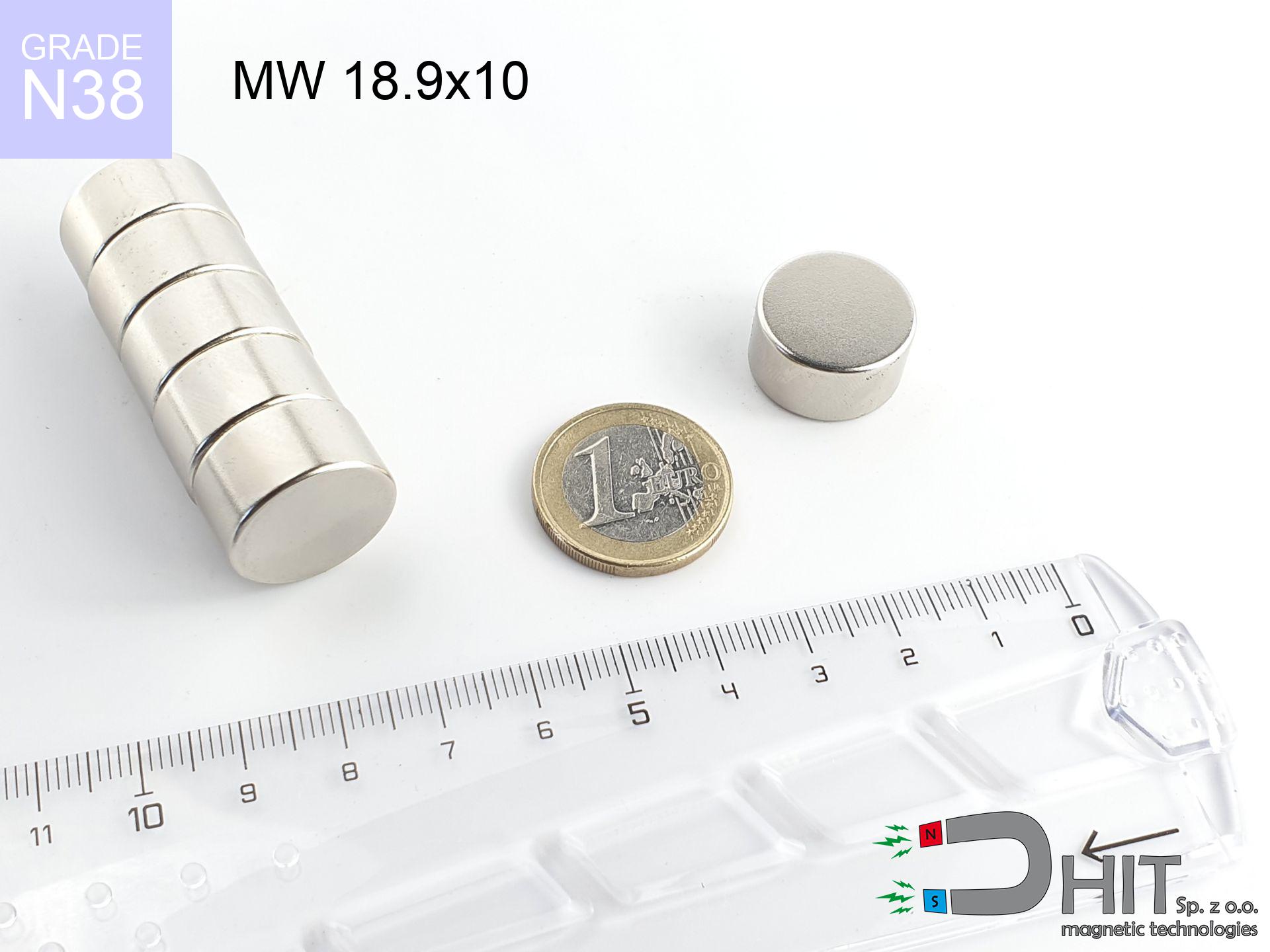
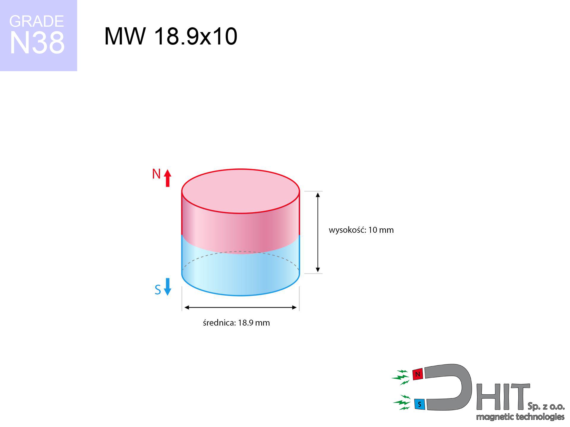
MW 18.9x10 / N38 - cylindrical magnet
cylindrical magnet
Catalog no 010036
GTIN/EAN: 5906301810353
Diameter Ø
18.9 mm [±0,1 mm]
Height
10 mm [±0,1 mm]
Weight
21.04 g
Magnetization Direction
→ diametrical
Load capacity
11.68 kg / 114.54 N
Magnetic Induction
450.35 mT / 4503 Gs
Coating
[NiCuNi] Nickel
11.07 ZŁ with VAT / pcs + price for transport
9.00 ZŁ net + 23% VAT / pcs
bulk discounts:
Need more?
Give us a call
+48 888 99 98 98
alternatively contact us by means of
contact form
our website.
Specifications as well as structure of neodymium magnets can be tested with our
online calculation tool.
Same-day shipping for orders placed before 14:00.
Technical details - MW 18.9x10 / N38 - cylindrical magnet
Specification / characteristics - MW 18.9x10 / N38 - cylindrical magnet
| properties | values |
|---|---|
| Cat. no. | 010036 |
| GTIN/EAN | 5906301810353 |
| Production/Distribution | Dhit sp. z o.o. |
| Country of origin | Poland / China / Germany |
| Customs code | 85059029 |
| Diameter Ø | 18.9 mm [±0,1 mm] |
| Height | 10 mm [±0,1 mm] |
| Weight | 21.04 g |
| Magnetization Direction | → diametrical |
| Load capacity ~ ? | 11.68 kg / 114.54 N |
| Magnetic Induction ~ ? | 450.35 mT / 4503 Gs |
| Coating | [NiCuNi] Nickel |
| Manufacturing Tolerance | ±0.1 mm |
Magnetic properties of material N38
| properties | values | units |
|---|---|---|
| remenance Br [min. - max.] ? | 12.2-12.6 | kGs |
| remenance Br [min. - max.] ? | 1220-1260 | mT |
| coercivity bHc ? | 10.8-11.5 | kOe |
| coercivity bHc ? | 860-915 | kA/m |
| actual internal force iHc | ≥ 12 | kOe |
| actual internal force iHc | ≥ 955 | kA/m |
| energy density [min. - max.] ? | 36-38 | BH max MGOe |
| energy density [min. - max.] ? | 287-303 | BH max KJ/m |
| max. temperature ? | ≤ 80 | °C |
Physical properties of sintered neodymium magnets Nd2Fe14B at 20°C
| properties | values | units |
|---|---|---|
| Vickers hardness | ≥550 | Hv |
| Density | ≥7.4 | g/cm3 |
| Curie Temperature TC | 312 - 380 | °C |
| Curie Temperature TF | 593 - 716 | °F |
| Specific resistance | 150 | μΩ⋅cm |
| Bending strength | 250 | MPa |
| Compressive strength | 1000~1100 | MPa |
| Thermal expansion parallel (∥) to orientation (M) | (3-4) x 10-6 | °C-1 |
| Thermal expansion perpendicular (⊥) to orientation (M) | -(1-3) x 10-6 | °C-1 |
| Young's modulus | 1.7 x 10⁴ | kg/mm² |
Technical modeling of the product - data
Presented information represent the outcome of a mathematical calculation. Values were calculated on models for the class Nd2Fe14B. Real-world parameters might slightly differ from theoretical values. Treat these calculations as a supplementary guide when designing systems.
Table 1: Static pull force (force vs gap) - power drop
MW 18.9x10 / N38
| Distance (mm) | Induction (Gauss) / mT | Pull Force (kg/lbs/g/N) | Risk Status |
|---|---|---|---|
| 0 mm |
4502 Gs
450.2 mT
|
11.68 kg / 25.75 lbs
11680.0 g / 114.6 N
|
critical level |
| 1 mm |
4050 Gs
405.0 mT
|
9.46 kg / 20.85 lbs
9455.2 g / 92.8 N
|
warning |
| 2 mm |
3587 Gs
358.7 mT
|
7.42 kg / 16.35 lbs
7416.3 g / 72.8 N
|
warning |
| 3 mm |
3139 Gs
313.9 mT
|
5.68 kg / 12.52 lbs
5678.8 g / 55.7 N
|
warning |
| 5 mm |
2346 Gs
234.6 mT
|
3.17 kg / 6.99 lbs
3172.5 g / 31.1 N
|
warning |
| 10 mm |
1100 Gs
110.0 mT
|
0.70 kg / 1.54 lbs
696.7 g / 6.8 N
|
weak grip |
| 15 mm |
554 Gs
55.4 mT
|
0.18 kg / 0.39 lbs
176.7 g / 1.7 N
|
weak grip |
| 20 mm |
308 Gs
30.8 mT
|
0.05 kg / 0.12 lbs
54.6 g / 0.5 N
|
weak grip |
| 30 mm |
120 Gs
12.0 mT
|
0.01 kg / 0.02 lbs
8.3 g / 0.1 N
|
weak grip |
| 50 mm |
32 Gs
3.2 mT
|
0.00 kg / 0.00 lbs
0.6 g / 0.0 N
|
weak grip |
Table 2: Slippage force (wall)
MW 18.9x10 / N38
| Distance (mm) | Friction coefficient | Pull Force (kg/lbs/g/N) |
|---|---|---|
| 0 mm | Stal (~0.2) |
2.34 kg / 5.15 lbs
2336.0 g / 22.9 N
|
| 1 mm | Stal (~0.2) |
1.89 kg / 4.17 lbs
1892.0 g / 18.6 N
|
| 2 mm | Stal (~0.2) |
1.48 kg / 3.27 lbs
1484.0 g / 14.6 N
|
| 3 mm | Stal (~0.2) |
1.14 kg / 2.50 lbs
1136.0 g / 11.1 N
|
| 5 mm | Stal (~0.2) |
0.63 kg / 1.40 lbs
634.0 g / 6.2 N
|
| 10 mm | Stal (~0.2) |
0.14 kg / 0.31 lbs
140.0 g / 1.4 N
|
| 15 mm | Stal (~0.2) |
0.04 kg / 0.08 lbs
36.0 g / 0.4 N
|
| 20 mm | Stal (~0.2) |
0.01 kg / 0.02 lbs
10.0 g / 0.1 N
|
| 30 mm | Stal (~0.2) |
0.00 kg / 0.00 lbs
2.0 g / 0.0 N
|
| 50 mm | Stal (~0.2) |
0.00 kg / 0.00 lbs
0.0 g / 0.0 N
|
Table 3: Wall mounting (shearing) - behavior on slippery surfaces
MW 18.9x10 / N38
| Surface type | Friction coefficient / % Mocy | Max load (kg/lbs/g/N) |
|---|---|---|
| Raw steel |
µ = 0.3
30% Nominalnej Siły
|
3.50 kg / 7.72 lbs
3504.0 g / 34.4 N
|
| Painted steel (standard) |
µ = 0.2
20% Nominalnej Siły
|
2.34 kg / 5.15 lbs
2336.0 g / 22.9 N
|
| Oily/slippery steel |
µ = 0.1
10% Nominalnej Siły
|
1.17 kg / 2.57 lbs
1168.0 g / 11.5 N
|
| Magnet with anti-slip rubber |
µ = 0.5
50% Nominalnej Siły
|
5.84 kg / 12.87 lbs
5840.0 g / 57.3 N
|
Table 4: Steel thickness (substrate influence) - sheet metal selection
MW 18.9x10 / N38
| Steel thickness (mm) | % power | Real pull force (kg/lbs/g/N) |
|---|---|---|
| 0.5 mm |
|
0.58 kg / 1.29 lbs
584.0 g / 5.7 N
|
| 1 mm |
|
1.46 kg / 3.22 lbs
1460.0 g / 14.3 N
|
| 2 mm |
|
2.92 kg / 6.44 lbs
2920.0 g / 28.6 N
|
| 3 mm |
|
4.38 kg / 9.66 lbs
4380.0 g / 43.0 N
|
| 5 mm |
|
7.30 kg / 16.09 lbs
7300.0 g / 71.6 N
|
| 10 mm |
|
11.68 kg / 25.75 lbs
11680.0 g / 114.6 N
|
| 11 mm |
|
11.68 kg / 25.75 lbs
11680.0 g / 114.6 N
|
| 12 mm |
|
11.68 kg / 25.75 lbs
11680.0 g / 114.6 N
|
Table 5: Working in heat (material behavior) - thermal limit
MW 18.9x10 / N38
| Ambient temp. (°C) | Power loss | Remaining pull (kg/lbs/g/N) | Status |
|---|---|---|---|
| 20 °C | 0.0% |
11.68 kg / 25.75 lbs
11680.0 g / 114.6 N
|
OK |
| 40 °C | -2.2% |
11.42 kg / 25.18 lbs
11423.0 g / 112.1 N
|
OK |
| 60 °C | -4.4% |
11.17 kg / 24.62 lbs
11166.1 g / 109.5 N
|
OK |
| 80 °C | -6.6% |
10.91 kg / 24.05 lbs
10909.1 g / 107.0 N
|
|
| 100 °C | -28.8% |
8.32 kg / 18.33 lbs
8316.2 g / 81.6 N
|
Table 6: Magnet-Magnet interaction (attraction) - field collision
MW 18.9x10 / N38
| Gap (mm) | Attraction (kg/lbs) (N-S) | Lateral Force (kg/lbs/g/N) | Repulsion (kg/lbs) (N-N) |
|---|---|---|---|
| 0 mm |
35.05 kg / 77.28 lbs
5 600 Gs
|
5.26 kg / 11.59 lbs
5258 g / 51.6 N
|
N/A |
| 1 mm |
31.70 kg / 69.88 lbs
8 562 Gs
|
4.75 kg / 10.48 lbs
4754 g / 46.6 N
|
28.53 kg / 62.89 lbs
~0 Gs
|
| 2 mm |
28.38 kg / 62.56 lbs
8 101 Gs
|
4.26 kg / 9.38 lbs
4256 g / 41.8 N
|
25.54 kg / 56.30 lbs
~0 Gs
|
| 3 mm |
25.22 kg / 55.59 lbs
7 636 Gs
|
3.78 kg / 8.34 lbs
3782 g / 37.1 N
|
22.69 kg / 50.03 lbs
~0 Gs
|
| 5 mm |
19.53 kg / 43.05 lbs
6 720 Gs
|
2.93 kg / 6.46 lbs
2929 g / 28.7 N
|
17.57 kg / 38.75 lbs
~0 Gs
|
| 10 mm |
9.52 kg / 20.99 lbs
4 692 Gs
|
1.43 kg / 3.15 lbs
1428 g / 14.0 N
|
8.57 kg / 18.89 lbs
~0 Gs
|
| 20 mm |
2.09 kg / 4.61 lbs
2 199 Gs
|
0.31 kg / 0.69 lbs
314 g / 3.1 N
|
1.88 kg / 4.15 lbs
~0 Gs
|
| 50 mm |
0.06 kg / 0.13 lbs
372 Gs
|
0.01 kg / 0.02 lbs
9 g / 0.1 N
|
0.05 kg / 0.12 lbs
~0 Gs
|
| 60 mm |
0.03 kg / 0.06 lbs
241 Gs
|
0.00 kg / 0.01 lbs
4 g / 0.0 N
|
0.02 kg / 0.05 lbs
~0 Gs
|
| 70 mm |
0.01 kg / 0.03 lbs
164 Gs
|
0.00 kg / 0.00 lbs
2 g / 0.0 N
|
0.01 kg / 0.02 lbs
~0 Gs
|
| 80 mm |
0.01 kg / 0.01 lbs
116 Gs
|
0.00 kg / 0.00 lbs
1 g / 0.0 N
|
0.00 kg / 0.00 lbs
~0 Gs
|
| 90 mm |
0.00 kg / 0.01 lbs
86 Gs
|
0.00 kg / 0.00 lbs
0 g / 0.0 N
|
0.00 kg / 0.00 lbs
~0 Gs
|
| 100 mm |
0.00 kg / 0.00 lbs
65 Gs
|
0.00 kg / 0.00 lbs
0 g / 0.0 N
|
0.00 kg / 0.00 lbs
~0 Gs
|
Table 7: Hazards (implants) - warnings
MW 18.9x10 / N38
| Object / Device | Limit (Gauss) / mT | Safe distance |
|---|---|---|
| Pacemaker | 5 Gs (0.5 mT) | 10.0 cm |
| Hearing aid | 10 Gs (1.0 mT) | 8.0 cm |
| Timepiece | 20 Gs (2.0 mT) | 6.0 cm |
| Phone / Smartphone | 40 Gs (4.0 mT) | 5.0 cm |
| Remote | 50 Gs (5.0 mT) | 4.5 cm |
| Payment card | 400 Gs (40.0 mT) | 2.0 cm |
| HDD hard drive | 600 Gs (60.0 mT) | 1.5 cm |
Table 8: Collisions (kinetic energy) - warning
MW 18.9x10 / N38
| Start from (mm) | Speed (km/h) | Energy (J) | Predicted outcome |
|---|---|---|---|
| 10 mm |
24.63 km/h
(6.84 m/s)
|
0.49 J | |
| 30 mm |
41.18 km/h
(11.44 m/s)
|
1.38 J | |
| 50 mm |
53.13 km/h
(14.76 m/s)
|
2.29 J | |
| 100 mm |
75.14 km/h
(20.87 m/s)
|
4.58 J |
Table 9: Anti-corrosion coating durability
MW 18.9x10 / N38
| Technical parameter | Value / Description |
|---|---|
| Coating type | [NiCuNi] Nickel |
| Layer structure | Nickel - Copper - Nickel |
| Layer thickness | 10-20 µm |
| Salt spray test (SST) ? | 24 h |
| Recommended environment | Indoors only (dry) |
Table 10: Construction data (Pc)
MW 18.9x10 / N38
| Parameter | Value | SI Unit / Description |
|---|---|---|
| Magnetic Flux | 12 775 Mx | 127.7 µWb |
| Pc Coefficient | 0.61 | High (Stable) |
Table 11: Physics of underwater searching
MW 18.9x10 / N38
| Environment | Effective steel pull | Effect |
|---|---|---|
| Air (land) | 11.68 kg | Standard |
| Water (riverbed) |
13.37 kg
(+1.69 kg buoyancy gain)
|
+14.5% |
1. Shear force
*Note: On a vertical surface, the magnet retains only a fraction of its nominal pull.
2. Steel saturation
*Thin steel (e.g. 0.5mm PC case) significantly limits the holding force.
3. Temperature resistance
*For standard magnets, the critical limit is 80°C.
4. Demagnetization curve and operating point (B-H)
chart generated for the permeance coefficient Pc (Permeance Coefficient) = 0.61
The chart above illustrates the magnetic characteristics of the material within the second quadrant of the hysteresis loop. The solid red line represents the demagnetization curve (material potential), while the dashed blue line is the load line based on the magnet's geometry. The Pc (Permeance Coefficient), also known as the load line slope, is a dimensionless value that describes the relationship between the magnet's shape and its magnetic stability. The intersection of these two lines (the black dot) is the operating point — it determines the actual magnetic flux density generated by the magnet in this specific configuration. A higher Pc value means the magnet is more 'slender' (tall relative to its area), resulting in a higher operating point and better resistance to irreversible demagnetization caused by external fields or temperature. A value of 0.42 is relatively low (typical for flat magnets), meaning the operating point is closer to the 'knee' of the curve — caution is advised when operating at temperatures near the maximum limit to avoid strength loss.
Elemental analysis
| iron (Fe) | 64% – 68% |
| neodymium (Nd) | 29% – 32% |
| boron (B) | 1.1% – 1.2% |
| dysprosium (Dy) | 0.5% – 2.0% |
| coating (Ni-Cu-Ni) | < 0.05% |
Sustainability
| recyclability (EoL) | 100% |
| recycled raw materials | ~10% (pre-cons) |
| carbon footprint | low / zredukowany |
| waste code (EWC) | 16 02 16 |
Other deals

![SM 32x475 [2xM8] / N42 - magnetic separator](https://cdn3.dhit.pl/graphics/products/sm-32x475-2xm8-jot.jpg "SM 32x475 [2xM8] / N42 - magnetic separator")


Strengths and weaknesses of neodymium magnets.
Pros
- Their strength is maintained, and after approximately 10 years it drops only by ~1% (according to research),
- They possess excellent resistance to weakening of magnetic properties due to opposing magnetic fields,
- In other words, due to the glossy finish of silver, the element gains a professional look,
- They feature high magnetic induction at the operating surface, which affects their effectiveness,
- Made from properly selected components, these magnets show impressive resistance to high heat, enabling them to function (depending on their shape) at temperatures up to 230°C and above...
- Possibility of detailed modeling as well as optimizing to specific conditions,
- Fundamental importance in high-tech industry – they are used in magnetic memories, electromotive mechanisms, advanced medical instruments, as well as technologically advanced constructions.
- Thanks to concentrated force, small magnets offer high operating force, occupying minimum space,
Weaknesses
- At very strong impacts they can break, therefore we advise placing them in steel cases. A metal housing provides additional protection against damage and increases the magnet's durability.
- When exposed to high temperature, neodymium magnets suffer a drop in force. Often, when the temperature exceeds 80°C, their power decreases (depending on the size and shape of the magnet). For those who need magnets for extreme conditions, we offer [AH] versions withstanding up to 230°C
- When exposed to humidity, magnets usually rust. For applications outside, it is recommended to use protective magnets, such as magnets in rubber or plastics, which prevent oxidation as well as corrosion.
- Limited possibility of making nuts in the magnet and complicated shapes - preferred is casing - magnet mounting.
- Potential hazard related to microscopic parts of magnets are risky, when accidentally swallowed, which is particularly important in the context of child health protection. Furthermore, small components of these products can disrupt the diagnostic process medical in case of swallowing.
- High unit price – neodymium magnets have a higher price than other types of magnets (e.g. ferrite), which increases costs of application in large quantities
Holding force characteristics
Maximum lifting force for a neodymium magnet – what contributes to it?
- on a plate made of structural steel, perfectly concentrating the magnetic flux
- whose thickness equals approx. 10 mm
- characterized by lack of roughness
- without the slightest insulating layer between the magnet and steel
- under axial force direction (90-degree angle)
- at ambient temperature approx. 20 degrees Celsius
Key elements affecting lifting force
- Clearance – existence of foreign body (paint, tape, gap) acts as an insulator, which reduces capacity rapidly (even by 50% at 0.5 mm).
- Force direction – catalog parameter refers to detachment vertically. When applying parallel force, the magnet holds much less (often approx. 20-30% of nominal force).
- Substrate thickness – for full efficiency, the steel must be sufficiently thick. Thin sheet restricts the lifting capacity (the magnet "punches through" it).
- Plate material – mild steel gives the best results. Alloy steels reduce magnetic permeability and holding force.
- Surface structure – the more even the plate, the larger the contact zone and higher the lifting capacity. Unevenness creates an air distance.
- Thermal factor – hot environment reduces magnetic field. Exceeding the limit temperature can permanently damage the magnet.
Lifting capacity was assessed with the use of a polished steel plate of optimal thickness (min. 20 mm), under perpendicular detachment force, whereas under shearing force the lifting capacity is smaller. Additionally, even a slight gap between the magnet and the plate lowers the holding force.
Warnings
Warning for heart patients
Medical warning: Strong magnets can turn off heart devices and defibrillators. Do not approach if you have electronic implants.
Precision electronics
A strong magnetic field disrupts the functioning of compasses in smartphones and navigation systems. Do not bring magnets near a device to prevent damaging the sensors.
Adults only
Neodymium magnets are not toys. Eating multiple magnets can lead to them connecting inside the digestive tract, which constitutes a direct threat to life and requires urgent medical intervention.
Heat sensitivity
Monitor thermal conditions. Exposing the magnet above 80 degrees Celsius will ruin its properties and strength.
Protective goggles
NdFeB magnets are ceramic materials, meaning they are fragile like glass. Collision of two magnets leads to them shattering into shards.
Respect the power
Before use, check safety instructions. Uncontrolled attraction can destroy the magnet or hurt your hand. Be predictive.
Fire warning
Powder produced during machining of magnets is combustible. Avoid drilling into magnets without proper cooling and knowledge.
Bone fractures
Large magnets can crush fingers instantly. Do not place your hand betwixt two attracting surfaces.
Metal Allergy
Certain individuals have a contact allergy to nickel, which is the common plating for NdFeB magnets. Extended handling can result in skin redness. We suggest wear protective gloves.
Safe distance
Very strong magnetic fields can destroy records on payment cards, hard drives, and storage devices. Stay away of min. 10 cm.
Tabela kosztu i czasu dostawy
Płatność przed wysyłką:

GLS kurier
Przesyłka będzie u Ciebie za 2-3 dni
14.99 ZŁ

InPost Paczkomaty 24/7
Przesyłka będzie u Ciebie za 1-2 dni
12.30 ZŁ
Płatność przy odbiorze (pobranie):
GLS kurier
Przesyłka będzie u Ciebie za 1-2 dni
23.00 ZŁ
Rate the product
Your rating