
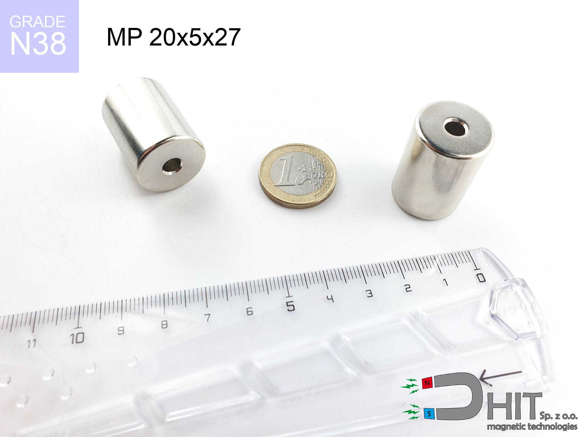
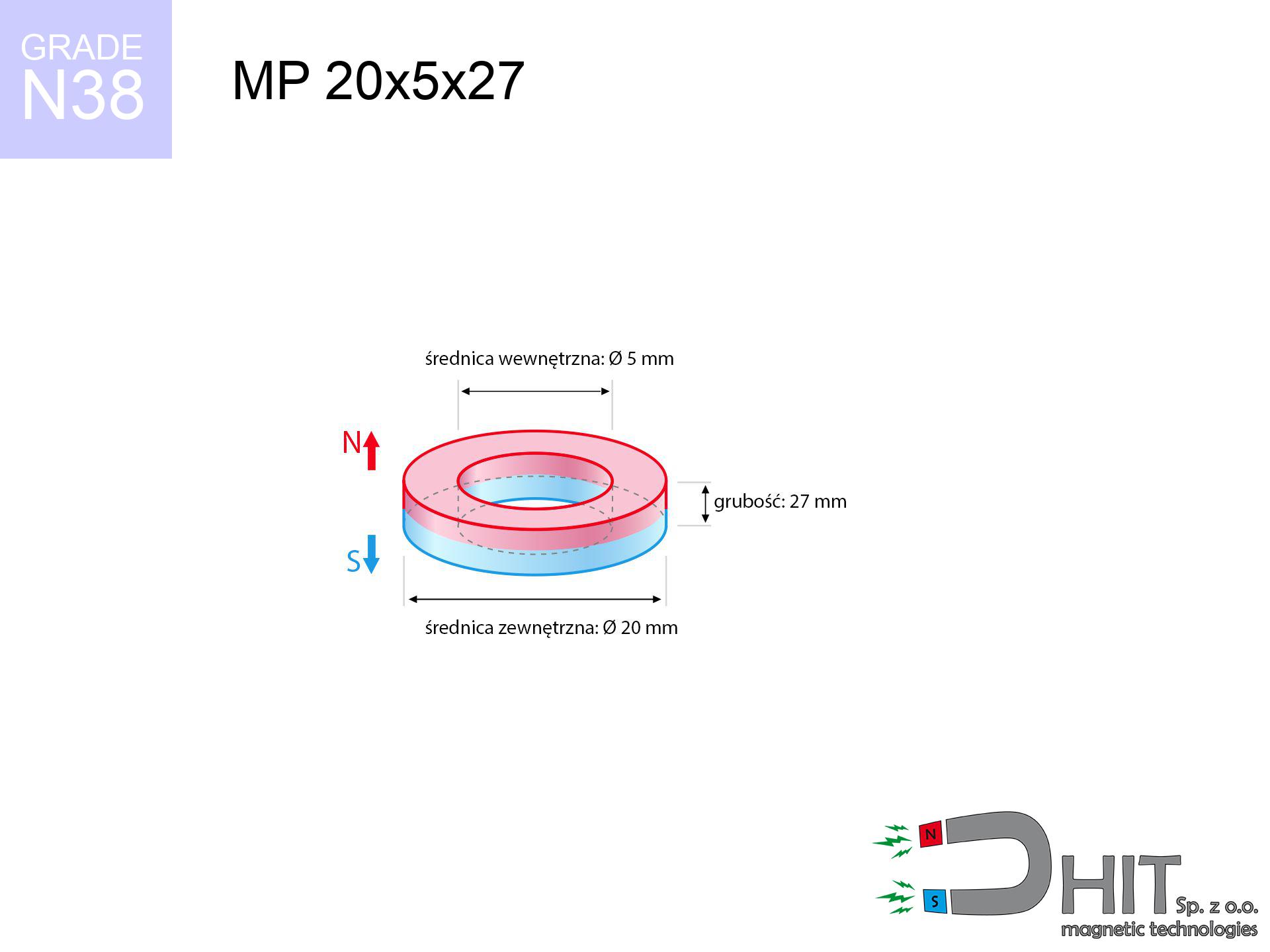
MP 20x5x27 / N38 - ring magnet
ring magnet
Catalog no 030185
GTIN/EAN: 5906301812029
Diameter
20 mm [±0,1 mm]
internal diameter Ø
5 mm [±0,1 mm]
Height
27 mm [±0,1 mm]
Weight
59.64 g
Magnetization Direction
↑ axial
Load capacity
10.36 kg / 101.60 N
Magnetic Induction
581.04 mT / 5810 Gs
Coating
[NiCuNi] Nickel
33.00 ZŁ with VAT / pcs + price for transport
26.83 ZŁ net + 23% VAT / pcs
bulk discounts:
Need more?
Contact us by phone
+48 888 99 98 98
alternatively get in touch by means of
inquiry form
the contact form page.
Lifting power as well as form of magnetic components can be tested with our
our magnetic calculator.
Orders placed before 14:00 will be shipped the same business day.
Technical parameters - MP 20x5x27 / N38 - ring magnet
Specification / characteristics - MP 20x5x27 / N38 - ring magnet
| properties | values |
|---|---|
| Cat. no. | 030185 |
| GTIN/EAN | 5906301812029 |
| Production/Distribution | Dhit sp. z o.o. |
| Country of origin | Poland / China / Germany |
| Customs code | 85059029 |
| Diameter | 20 mm [±0,1 mm] |
| internal diameter Ø | 5 mm [±0,1 mm] |
| Height | 27 mm [±0,1 mm] |
| Weight | 59.64 g |
| Magnetization Direction | ↑ axial |
| Load capacity ~ ? | 10.36 kg / 101.60 N |
| Magnetic Induction ~ ? | 581.04 mT / 5810 Gs |
| Coating | [NiCuNi] Nickel |
| Manufacturing Tolerance | ±0.1 mm |
Magnetic properties of material N38
| properties | values | units |
|---|---|---|
| remenance Br [min. - max.] ? | 12.2-12.6 | kGs |
| remenance Br [min. - max.] ? | 1220-1260 | mT |
| coercivity bHc ? | 10.8-11.5 | kOe |
| coercivity bHc ? | 860-915 | kA/m |
| actual internal force iHc | ≥ 12 | kOe |
| actual internal force iHc | ≥ 955 | kA/m |
| energy density [min. - max.] ? | 36-38 | BH max MGOe |
| energy density [min. - max.] ? | 287-303 | BH max KJ/m |
| max. temperature ? | ≤ 80 | °C |
Physical properties of sintered neodymium magnets Nd2Fe14B at 20°C
| properties | values | units |
|---|---|---|
| Vickers hardness | ≥550 | Hv |
| Density | ≥7.4 | g/cm3 |
| Curie Temperature TC | 312 - 380 | °C |
| Curie Temperature TF | 593 - 716 | °F |
| Specific resistance | 150 | μΩ⋅cm |
| Bending strength | 250 | MPa |
| Compressive strength | 1000~1100 | MPa |
| Thermal expansion parallel (∥) to orientation (M) | (3-4) x 10-6 | °C-1 |
| Thermal expansion perpendicular (⊥) to orientation (M) | -(1-3) x 10-6 | °C-1 |
| Young's modulus | 1.7 x 10⁴ | kg/mm² |
Physical simulation of the assembly - technical parameters
These data represent the direct effect of a engineering calculation. Values rely on models for the class Nd2Fe14B. Actual conditions might slightly differ from theoretical values. Please consider these data as a reference point for designers.
Table 1: Static force (pull vs distance) - power drop
MP 20x5x27 / N38
| Distance (mm) | Induction (Gauss) / mT | Pull Force (kg/lbs/g/N) | Risk Status |
|---|---|---|---|
| 0 mm |
5716 Gs
571.6 mT
|
10.36 kg / 22.84 LBS
10360.0 g / 101.6 N
|
dangerous! |
| 1 mm |
5288 Gs
528.8 mT
|
8.87 kg / 19.55 LBS
8865.5 g / 87.0 N
|
medium risk |
| 2 mm |
4861 Gs
486.1 mT
|
7.49 kg / 16.51 LBS
7491.0 g / 73.5 N
|
medium risk |
| 3 mm |
4446 Gs
444.6 mT
|
6.27 kg / 13.82 LBS
6267.5 g / 61.5 N
|
medium risk |
| 5 mm |
3677 Gs
367.7 mT
|
4.29 kg / 9.45 LBS
4285.9 g / 42.0 N
|
medium risk |
| 10 mm |
2216 Gs
221.6 mT
|
1.56 kg / 3.43 LBS
1557.1 g / 15.3 N
|
safe |
| 15 mm |
1354 Gs
135.4 mT
|
0.58 kg / 1.28 LBS
580.9 g / 5.7 N
|
safe |
| 20 mm |
864 Gs
86.4 mT
|
0.24 kg / 0.52 LBS
236.9 g / 2.3 N
|
safe |
| 30 mm |
405 Gs
40.5 mT
|
0.05 kg / 0.11 LBS
52.1 g / 0.5 N
|
safe |
| 50 mm |
133 Gs
13.3 mT
|
0.01 kg / 0.01 LBS
5.6 g / 0.1 N
|
safe |
Table 2: Slippage hold (vertical surface)
MP 20x5x27 / N38
| Distance (mm) | Friction coefficient | Pull Force (kg/lbs/g/N) |
|---|---|---|
| 0 mm | Stal (~0.2) |
2.07 kg / 4.57 LBS
2072.0 g / 20.3 N
|
| 1 mm | Stal (~0.2) |
1.77 kg / 3.91 LBS
1774.0 g / 17.4 N
|
| 2 mm | Stal (~0.2) |
1.50 kg / 3.30 LBS
1498.0 g / 14.7 N
|
| 3 mm | Stal (~0.2) |
1.25 kg / 2.76 LBS
1254.0 g / 12.3 N
|
| 5 mm | Stal (~0.2) |
0.86 kg / 1.89 LBS
858.0 g / 8.4 N
|
| 10 mm | Stal (~0.2) |
0.31 kg / 0.69 LBS
312.0 g / 3.1 N
|
| 15 mm | Stal (~0.2) |
0.12 kg / 0.26 LBS
116.0 g / 1.1 N
|
| 20 mm | Stal (~0.2) |
0.05 kg / 0.11 LBS
48.0 g / 0.5 N
|
| 30 mm | Stal (~0.2) |
0.01 kg / 0.02 LBS
10.0 g / 0.1 N
|
| 50 mm | Stal (~0.2) |
0.00 kg / 0.00 LBS
2.0 g / 0.0 N
|
Table 3: Wall mounting (shearing) - behavior on slippery surfaces
MP 20x5x27 / N38
| Surface type | Friction coefficient / % Mocy | Max load (kg/lbs/g/N) |
|---|---|---|
| Raw steel |
µ = 0.3
30% Nominalnej Siły
|
3.11 kg / 6.85 LBS
3108.0 g / 30.5 N
|
| Painted steel (standard) |
µ = 0.2
20% Nominalnej Siły
|
2.07 kg / 4.57 LBS
2072.0 g / 20.3 N
|
| Oily/slippery steel |
µ = 0.1
10% Nominalnej Siły
|
1.04 kg / 2.28 LBS
1036.0 g / 10.2 N
|
| Magnet with anti-slip rubber |
µ = 0.5
50% Nominalnej Siły
|
5.18 kg / 11.42 LBS
5180.0 g / 50.8 N
|
Table 4: Material efficiency (substrate influence) - sheet metal selection
MP 20x5x27 / N38
| Steel thickness (mm) | % power | Real pull force (kg/lbs/g/N) |
|---|---|---|
| 0.5 mm |
|
0.52 kg / 1.14 LBS
518.0 g / 5.1 N
|
| 1 mm |
|
1.30 kg / 2.85 LBS
1295.0 g / 12.7 N
|
| 2 mm |
|
2.59 kg / 5.71 LBS
2590.0 g / 25.4 N
|
| 3 mm |
|
3.89 kg / 8.56 LBS
3885.0 g / 38.1 N
|
| 5 mm |
|
6.48 kg / 14.27 LBS
6475.0 g / 63.5 N
|
| 10 mm |
|
10.36 kg / 22.84 LBS
10360.0 g / 101.6 N
|
| 11 mm |
|
10.36 kg / 22.84 LBS
10360.0 g / 101.6 N
|
| 12 mm |
|
10.36 kg / 22.84 LBS
10360.0 g / 101.6 N
|
Table 5: Thermal resistance (material behavior) - resistance threshold
MP 20x5x27 / N38
| Ambient temp. (°C) | Power loss | Remaining pull (kg/lbs/g/N) | Status |
|---|---|---|---|
| 20 °C | 0.0% |
10.36 kg / 22.84 LBS
10360.0 g / 101.6 N
|
OK |
| 40 °C | -2.2% |
10.13 kg / 22.34 LBS
10132.1 g / 99.4 N
|
OK |
| 60 °C | -4.4% |
9.90 kg / 21.83 LBS
9904.2 g / 97.2 N
|
OK |
| 80 °C | -6.6% |
9.68 kg / 21.33 LBS
9676.2 g / 94.9 N
|
|
| 100 °C | -28.8% |
7.38 kg / 16.26 LBS
7376.3 g / 72.4 N
|
Table 6: Magnet-Magnet interaction (repulsion) - field collision
MP 20x5x27 / N38
| Gap (mm) | Attraction (kg/lbs) (N-S) | Shear Force (kg/lbs/g/N) | Repulsion (kg/lbs) (N-N) |
|---|---|---|---|
| 0 mm |
44.24 kg / 97.54 LBS
6 064 Gs
|
6.64 kg / 14.63 LBS
6636 g / 65.1 N
|
N/A |
| 1 mm |
41.02 kg / 90.43 LBS
11 008 Gs
|
6.15 kg / 13.56 LBS
6153 g / 60.4 N
|
36.92 kg / 81.39 LBS
~0 Gs
|
| 2 mm |
37.86 kg / 83.47 LBS
10 576 Gs
|
5.68 kg / 12.52 LBS
5679 g / 55.7 N
|
34.07 kg / 75.12 LBS
~0 Gs
|
| 3 mm |
34.85 kg / 76.83 LBS
10 146 Gs
|
5.23 kg / 11.52 LBS
5227 g / 51.3 N
|
31.36 kg / 69.14 LBS
~0 Gs
|
| 5 mm |
29.30 kg / 64.58 LBS
9 303 Gs
|
4.39 kg / 9.69 LBS
4394 g / 43.1 N
|
26.37 kg / 58.13 LBS
~0 Gs
|
| 10 mm |
18.30 kg / 40.35 LBS
7 353 Gs
|
2.75 kg / 6.05 LBS
2745 g / 26.9 N
|
16.47 kg / 36.32 LBS
~0 Gs
|
| 20 mm |
6.65 kg / 14.66 LBS
4 432 Gs
|
1.00 kg / 2.20 LBS
997 g / 9.8 N
|
5.98 kg / 13.19 LBS
~0 Gs
|
| 50 mm |
0.45 kg / 1.00 LBS
1 159 Gs
|
0.07 kg / 0.15 LBS
68 g / 0.7 N
|
0.41 kg / 0.90 LBS
~0 Gs
|
| 60 mm |
0.22 kg / 0.49 LBS
811 Gs
|
0.03 kg / 0.07 LBS
33 g / 0.3 N
|
0.20 kg / 0.44 LBS
~0 Gs
|
| 70 mm |
0.12 kg / 0.26 LBS
589 Gs
|
0.02 kg / 0.04 LBS
18 g / 0.2 N
|
0.11 kg / 0.23 LBS
~0 Gs
|
| 80 mm |
0.07 kg / 0.14 LBS
440 Gs
|
0.01 kg / 0.02 LBS
10 g / 0.1 N
|
0.06 kg / 0.13 LBS
~0 Gs
|
| 90 mm |
0.04 kg / 0.09 LBS
338 Gs
|
0.01 kg / 0.01 LBS
6 g / 0.1 N
|
0.03 kg / 0.08 LBS
~0 Gs
|
| 100 mm |
0.02 kg / 0.05 LBS
265 Gs
|
0.00 kg / 0.01 LBS
4 g / 0.0 N
|
0.02 kg / 0.05 LBS
~0 Gs
|
Table 7: Hazards (implants) - precautionary measures
MP 20x5x27 / N38
| Object / Device | Limit (Gauss) / mT | Safe distance |
|---|---|---|
| Pacemaker | 5 Gs (0.5 mT) | 18.0 cm |
| Hearing aid | 10 Gs (1.0 mT) | 14.0 cm |
| Timepiece | 20 Gs (2.0 mT) | 11.0 cm |
| Mobile device | 40 Gs (4.0 mT) | 8.5 cm |
| Remote | 50 Gs (5.0 mT) | 7.5 cm |
| Payment card | 400 Gs (40.0 mT) | 3.5 cm |
| HDD hard drive | 600 Gs (60.0 mT) | 2.5 cm |
Table 8: Collisions (cracking risk) - warning
MP 20x5x27 / N38
| Start from (mm) | Speed (km/h) | Energy (J) | Predicted outcome |
|---|---|---|---|
| 10 mm |
14.49 km/h
(4.02 m/s)
|
0.48 J | |
| 30 mm |
23.09 km/h
(6.42 m/s)
|
1.23 J | |
| 50 mm |
29.73 km/h
(8.26 m/s)
|
2.03 J | |
| 100 mm |
42.03 km/h
(11.68 m/s)
|
4.07 J |
Table 9: Anti-corrosion coating durability
MP 20x5x27 / N38
| Technical parameter | Value / Description |
|---|---|
| Coating type | [NiCuNi] Nickel |
| Layer structure | Nickel - Copper - Nickel |
| Layer thickness | 10-20 µm |
| Salt spray test (SST) ? | 24 h |
| Recommended environment | Indoors only (dry) |
Table 10: Construction data (Pc)
MP 20x5x27 / N38
| Parameter | Value | SI Unit / Description |
|---|---|---|
| Magnetic Flux | 14 314 Mx | 143.1 µWb |
| Pc Coefficient | 1.16 | High (Stable) |
Table 11: Hydrostatics and buoyancy
MP 20x5x27 / N38
| Environment | Effective steel pull | Effect |
|---|---|---|
| Air (land) | 10.36 kg | Standard |
| Water (riverbed) |
11.86 kg
(+1.50 kg buoyancy gain)
|
+14.5% |
1. Shear force
*Caution: On a vertical surface, the magnet retains merely a fraction of its nominal pull.
2. Plate thickness effect
*Thin metal sheet (e.g. computer case) significantly reduces the holding force.
3. Temperature resistance
*For N38 material, the critical limit is 80°C.
4. Demagnetization curve and operating point (B-H)
chart generated for the permeance coefficient Pc (Permeance Coefficient) = 1.16
The chart above illustrates the magnetic characteristics of the material within the second quadrant of the hysteresis loop. The solid red line represents the demagnetization curve (material potential), while the dashed blue line is the load line based on the magnet's geometry. The Pc (Permeance Coefficient), also known as the load line slope, is a dimensionless value that describes the relationship between the magnet's shape and its magnetic stability. The intersection of these two lines (the black dot) is the operating point — it determines the actual magnetic flux density generated by the magnet in this specific configuration. A higher Pc value means the magnet is more 'slender' (tall relative to its area), resulting in a higher operating point and better resistance to irreversible demagnetization caused by external fields or temperature. A value of 0.42 is relatively low (typical for flat magnets), meaning the operating point is closer to the 'knee' of the curve — caution is advised when operating at temperatures near the maximum limit to avoid strength loss.
Material specification
| iron (Fe) | 64% – 68% |
| neodymium (Nd) | 29% – 32% |
| boron (B) | 1.1% – 1.2% |
| dysprosium (Dy) | 0.5% – 2.0% |
| coating (Ni-Cu-Ni) | < 0.05% |
Environmental data
| recyclability (EoL) | 100% |
| recycled raw materials | ~10% (pre-cons) |
| carbon footprint | low / zredukowany |
| waste code (EWC) | 16 02 16 |
Other products


Strengths as well as weaknesses of neodymium magnets.
Advantages
- Their strength remains stable, and after approximately 10 years it drops only by ~1% (theoretically),
- They show high resistance to demagnetization induced by external disturbances,
- A magnet with a metallic gold surface looks better,
- Neodymium magnets deliver maximum magnetic induction on a small surface, which increases force concentration,
- Through (adequate) combination of ingredients, they can achieve high thermal strength, enabling functioning at temperatures approaching 230°C and above...
- Considering the option of accurate forming and customization to specialized projects, magnetic components can be modeled in a wide range of geometric configurations, which makes them more universal,
- Huge importance in innovative solutions – they are utilized in mass storage devices, motor assemblies, diagnostic systems, as well as other advanced devices.
- Compactness – despite small sizes they provide effective action, making them ideal for precision applications
Limitations
- To avoid cracks under impact, we recommend using special steel housings. Such a solution secures the magnet and simultaneously increases its durability.
- NdFeB magnets lose power when exposed to high temperatures. After reaching 80°C, many of them experience permanent drop of power (a factor is the shape as well as dimensions of the magnet). We offer magnets specially adapted to work at temperatures up to 230°C marked [AH], which are extremely resistant to heat
- They oxidize in a humid environment. For use outdoors we suggest using waterproof magnets e.g. in rubber, plastic
- Due to limitations in realizing nuts and complicated forms in magnets, we propose using casing - magnetic mount.
- Potential hazard related to microscopic parts of magnets are risky, in case of ingestion, which becomes key in the context of child safety. Additionally, small components of these devices can complicate diagnosis medical in case of swallowing.
- Higher cost of purchase is a significant factor to consider compared to ceramic magnets, especially in budget applications
Holding force characteristics
Highest magnetic holding force – what contributes to it?
- using a plate made of low-carbon steel, acting as a magnetic yoke
- whose thickness is min. 10 mm
- with a plane free of scratches
- with total lack of distance (without coatings)
- for force acting at a right angle (pull-off, not shear)
- in temp. approx. 20°C
Practical lifting capacity: influencing factors
- Space between surfaces – every millimeter of separation (caused e.g. by varnish or unevenness) significantly weakens the pulling force, often by half at just 0.5 mm.
- Pull-off angle – remember that the magnet has greatest strength perpendicularly. Under sliding down, the holding force drops significantly, often to levels of 20-30% of the maximum value.
- Steel thickness – insufficiently thick plate does not accept the full field, causing part of the flux to be lost into the air.
- Chemical composition of the base – low-carbon steel attracts best. Alloy admixtures lower magnetic properties and holding force.
- Surface quality – the more even the surface, the better the adhesion and stronger the hold. Roughness creates an air distance.
- Operating temperature – neodymium magnets have a sensitivity to temperature. When it is hot they are weaker, and at low temperatures gain strength (up to a certain limit).
Lifting capacity testing was performed on a smooth plate of optimal thickness, under a perpendicular pulling force, however under attempts to slide the magnet the holding force is lower. Moreover, even a small distance between the magnet’s surface and the plate lowers the holding force.
Safety rules for work with neodymium magnets
Dust explosion hazard
Fire warning: Rare earth powder is explosive. Do not process magnets in home conditions as this risks ignition.
Metal Allergy
It is widely known that the nickel plating (standard magnet coating) is a potent allergen. If your skin reacts to metals, refrain from direct skin contact and opt for coated magnets.
Choking Hazard
Only for adults. Tiny parts pose a choking risk, leading to serious injuries. Store away from kids and pets.
Impact on smartphones
Navigation devices and smartphones are extremely sensitive to magnetic fields. Direct contact with a strong magnet can decalibrate the internal compass in your phone.
Safe distance
Do not bring magnets close to a wallet, laptop, or TV. The magnetic field can permanently damage these devices and wipe information from cards.
Maximum temperature
Do not overheat. Neodymium magnets are sensitive to heat. If you need operation above 80°C, inquire about HT versions (H, SH, UH).
Safe operation
Exercise caution. Rare earth magnets attract from a distance and snap with huge force, often faster than you can react.
Crushing risk
Big blocks can break fingers instantly. Do not place your hand between two attracting surfaces.
Beware of splinters
Despite metallic appearance, neodymium is brittle and cannot withstand shocks. Do not hit, as the magnet may shatter into sharp, dangerous pieces.
Implant safety
Health Alert: Strong magnets can turn off heart devices and defibrillators. Stay away if you have electronic implants.
Tabela kosztu i czasu dostawy
Płatność przed wysyłką:

GLS kurier
Przesyłka będzie u Ciebie za 2-3 dni
14.99 ZŁ

InPost Paczkomaty 24/7
Przesyłka będzie u Ciebie za 1-2 dni
12.30 ZŁ
Płatność przy odbiorze (pobranie):
GLS kurier
Przesyłka będzie u Ciebie za 1-2 dni
23.00 ZŁ
Rate the product
Your rating