

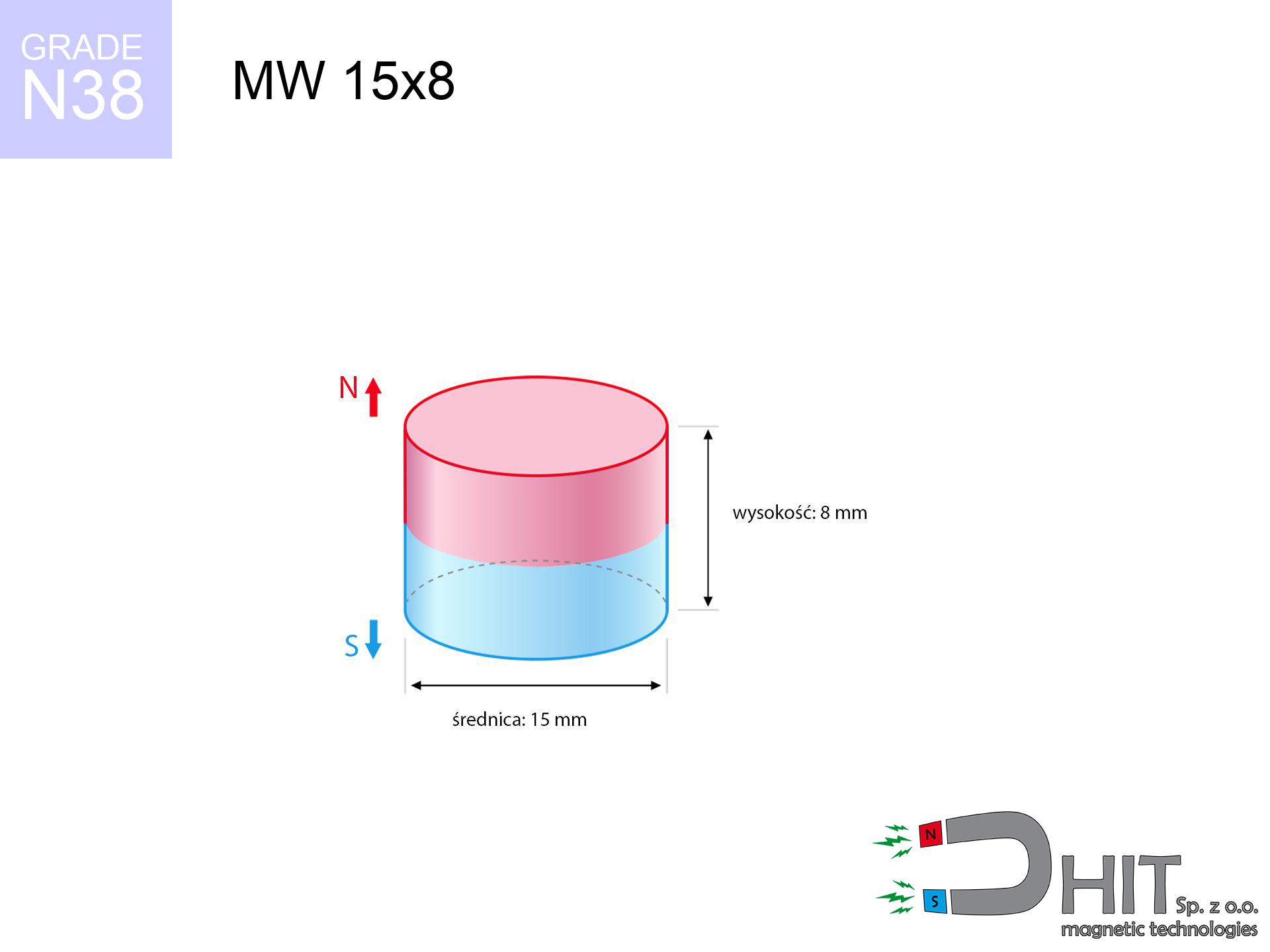
MW 15x8 / N38 - cylindrical magnet
cylindrical magnet
Catalog no 010032
GTIN/EAN: 5906301810315
Diameter Ø
15 mm [±0,1 mm]
Height
8 mm [±0,1 mm]
Weight
10.6 g
Magnetization Direction
↑ axial
Load capacity
7.37 kg / 72.28 N
Magnetic Induction
451.96 mT / 4520 Gs
Coating
[NiCuNi] Nickel
4.92 ZŁ with VAT / pcs + price for transport
4.00 ZŁ net + 23% VAT / pcs
bulk discounts:
Need more?
Call us
+48 888 99 98 98
otherwise get in touch using
inquiry form
the contact section.
Lifting power and appearance of neodymium magnets can be checked on our
our magnetic calculator.
Same-day shipping for orders placed before 14:00.
Detailed specification - MW 15x8 / N38 - cylindrical magnet
Specification / characteristics - MW 15x8 / N38 - cylindrical magnet
| properties | values |
|---|---|
| Cat. no. | 010032 |
| GTIN/EAN | 5906301810315 |
| Production/Distribution | Dhit sp. z o.o. |
| Country of origin | Poland / China / Germany |
| Customs code | 85059029 |
| Diameter Ø | 15 mm [±0,1 mm] |
| Height | 8 mm [±0,1 mm] |
| Weight | 10.6 g |
| Magnetization Direction | ↑ axial |
| Load capacity ~ ? | 7.37 kg / 72.28 N |
| Magnetic Induction ~ ? | 451.96 mT / 4520 Gs |
| Coating | [NiCuNi] Nickel |
| Manufacturing Tolerance | ±0.1 mm |
Magnetic properties of material N38
| properties | values | units |
|---|---|---|
| remenance Br [min. - max.] ? | 12.2-12.6 | kGs |
| remenance Br [min. - max.] ? | 1220-1260 | mT |
| coercivity bHc ? | 10.8-11.5 | kOe |
| coercivity bHc ? | 860-915 | kA/m |
| actual internal force iHc | ≥ 12 | kOe |
| actual internal force iHc | ≥ 955 | kA/m |
| energy density [min. - max.] ? | 36-38 | BH max MGOe |
| energy density [min. - max.] ? | 287-303 | BH max KJ/m |
| max. temperature ? | ≤ 80 | °C |
Physical properties of sintered neodymium magnets Nd2Fe14B at 20°C
| properties | values | units |
|---|---|---|
| Vickers hardness | ≥550 | Hv |
| Density | ≥7.4 | g/cm3 |
| Curie Temperature TC | 312 - 380 | °C |
| Curie Temperature TF | 593 - 716 | °F |
| Specific resistance | 150 | μΩ⋅cm |
| Bending strength | 250 | MPa |
| Compressive strength | 1000~1100 | MPa |
| Thermal expansion parallel (∥) to orientation (M) | (3-4) x 10-6 | °C-1 |
| Thermal expansion perpendicular (⊥) to orientation (M) | -(1-3) x 10-6 | °C-1 |
| Young's modulus | 1.7 x 10⁴ | kg/mm² |
Physical modeling of the assembly - technical parameters
The following values represent the result of a physical calculation. Values were calculated on models for the material Nd2Fe14B. Actual performance may differ. Use these data as a reference point during assembly planning.
Table 1: Static force (pull vs distance) - power drop
MW 15x8 / N38
| Distance (mm) | Induction (Gauss) / mT | Pull Force (kg/lbs/g/N) | Risk Status |
|---|---|---|---|
| 0 mm |
4518 Gs
451.8 mT
|
7.37 kg / 16.25 pounds
7370.0 g / 72.3 N
|
medium risk |
| 1 mm |
3944 Gs
394.4 mT
|
5.62 kg / 12.38 pounds
5616.2 g / 55.1 N
|
medium risk |
| 2 mm |
3362 Gs
336.2 mT
|
4.08 kg / 9.00 pounds
4083.1 g / 40.1 N
|
medium risk |
| 3 mm |
2820 Gs
282.0 mT
|
2.87 kg / 6.33 pounds
2871.9 g / 28.2 N
|
medium risk |
| 5 mm |
1931 Gs
193.1 mT
|
1.35 kg / 2.97 pounds
1346.9 g / 13.2 N
|
safe |
| 10 mm |
763 Gs
76.3 mT
|
0.21 kg / 0.46 pounds
210.3 g / 2.1 N
|
safe |
| 15 mm |
349 Gs
34.9 mT
|
0.04 kg / 0.10 pounds
44.0 g / 0.4 N
|
safe |
| 20 mm |
184 Gs
18.4 mT
|
0.01 kg / 0.03 pounds
12.2 g / 0.1 N
|
safe |
| 30 mm |
68 Gs
6.8 mT
|
0.00 kg / 0.00 pounds
1.7 g / 0.0 N
|
safe |
| 50 mm |
17 Gs
1.7 mT
|
0.00 kg / 0.00 pounds
0.1 g / 0.0 N
|
safe |
Table 2: Vertical force (wall)
MW 15x8 / N38
| Distance (mm) | Friction coefficient | Pull Force (kg/lbs/g/N) |
|---|---|---|
| 0 mm | Stal (~0.2) |
1.47 kg / 3.25 pounds
1474.0 g / 14.5 N
|
| 1 mm | Stal (~0.2) |
1.12 kg / 2.48 pounds
1124.0 g / 11.0 N
|
| 2 mm | Stal (~0.2) |
0.82 kg / 1.80 pounds
816.0 g / 8.0 N
|
| 3 mm | Stal (~0.2) |
0.57 kg / 1.27 pounds
574.0 g / 5.6 N
|
| 5 mm | Stal (~0.2) |
0.27 kg / 0.60 pounds
270.0 g / 2.6 N
|
| 10 mm | Stal (~0.2) |
0.04 kg / 0.09 pounds
42.0 g / 0.4 N
|
| 15 mm | Stal (~0.2) |
0.01 kg / 0.02 pounds
8.0 g / 0.1 N
|
| 20 mm | Stal (~0.2) |
0.00 kg / 0.00 pounds
2.0 g / 0.0 N
|
| 30 mm | Stal (~0.2) |
0.00 kg / 0.00 pounds
0.0 g / 0.0 N
|
| 50 mm | Stal (~0.2) |
0.00 kg / 0.00 pounds
0.0 g / 0.0 N
|
Table 3: Wall mounting (sliding) - behavior on slippery surfaces
MW 15x8 / N38
| Surface type | Friction coefficient / % Mocy | Max load (kg/lbs/g/N) |
|---|---|---|
| Raw steel |
µ = 0.3
30% Nominalnej Siły
|
2.21 kg / 4.87 pounds
2211.0 g / 21.7 N
|
| Painted steel (standard) |
µ = 0.2
20% Nominalnej Siły
|
1.47 kg / 3.25 pounds
1474.0 g / 14.5 N
|
| Oily/slippery steel |
µ = 0.1
10% Nominalnej Siły
|
0.74 kg / 1.62 pounds
737.0 g / 7.2 N
|
| Magnet with anti-slip rubber |
µ = 0.5
50% Nominalnej Siły
|
3.69 kg / 8.12 pounds
3685.0 g / 36.1 N
|
Table 4: Material efficiency (saturation) - sheet metal selection
MW 15x8 / N38
| Steel thickness (mm) | % power | Real pull force (kg/lbs/g/N) |
|---|---|---|
| 0.5 mm |
|
0.74 kg / 1.62 pounds
737.0 g / 7.2 N
|
| 1 mm |
|
1.84 kg / 4.06 pounds
1842.5 g / 18.1 N
|
| 2 mm |
|
3.69 kg / 8.12 pounds
3685.0 g / 36.1 N
|
| 3 mm |
|
5.53 kg / 12.19 pounds
5527.5 g / 54.2 N
|
| 5 mm |
|
7.37 kg / 16.25 pounds
7370.0 g / 72.3 N
|
| 10 mm |
|
7.37 kg / 16.25 pounds
7370.0 g / 72.3 N
|
| 11 mm |
|
7.37 kg / 16.25 pounds
7370.0 g / 72.3 N
|
| 12 mm |
|
7.37 kg / 16.25 pounds
7370.0 g / 72.3 N
|
Table 5: Thermal stability (material behavior) - power drop
MW 15x8 / N38
| Ambient temp. (°C) | Power loss | Remaining pull (kg/lbs/g/N) | Status |
|---|---|---|---|
| 20 °C | 0.0% |
7.37 kg / 16.25 pounds
7370.0 g / 72.3 N
|
OK |
| 40 °C | -2.2% |
7.21 kg / 15.89 pounds
7207.9 g / 70.7 N
|
OK |
| 60 °C | -4.4% |
7.05 kg / 15.53 pounds
7045.7 g / 69.1 N
|
OK |
| 80 °C | -6.6% |
6.88 kg / 15.18 pounds
6883.6 g / 67.5 N
|
|
| 100 °C | -28.8% |
5.25 kg / 11.57 pounds
5247.4 g / 51.5 N
|
Table 6: Two magnets (repulsion) - field collision
MW 15x8 / N38
| Gap (mm) | Attraction (kg/lbs) (N-S) | Shear Strength (kg/lbs/g/N) | Repulsion (kg/lbs) (N-N) |
|---|---|---|---|
| 0 mm |
22.23 kg / 49.02 pounds
5 606 Gs
|
3.34 kg / 7.35 pounds
3335 g / 32.7 N
|
N/A |
| 1 mm |
19.55 kg / 43.11 pounds
8 473 Gs
|
2.93 kg / 6.47 pounds
2933 g / 28.8 N
|
17.60 kg / 38.80 pounds
~0 Gs
|
| 2 mm |
16.94 kg / 37.35 pounds
7 887 Gs
|
2.54 kg / 5.60 pounds
2541 g / 24.9 N
|
15.25 kg / 33.62 pounds
~0 Gs
|
| 3 mm |
14.52 kg / 32.00 pounds
7 301 Gs
|
2.18 kg / 4.80 pounds
2178 g / 21.4 N
|
13.07 kg / 28.80 pounds
~0 Gs
|
| 5 mm |
10.37 kg / 22.85 pounds
6 169 Gs
|
1.55 kg / 3.43 pounds
1555 g / 15.3 N
|
9.33 kg / 20.57 pounds
~0 Gs
|
| 10 mm |
4.06 kg / 8.96 pounds
3 862 Gs
|
0.61 kg / 1.34 pounds
609 g / 6.0 N
|
3.66 kg / 8.06 pounds
~0 Gs
|
| 20 mm |
0.63 kg / 1.40 pounds
1 526 Gs
|
0.10 kg / 0.21 pounds
95 g / 0.9 N
|
0.57 kg / 1.26 pounds
~0 Gs
|
| 50 mm |
0.01 kg / 0.03 pounds
215 Gs
|
0.00 kg / 0.00 pounds
2 g / 0.0 N
|
0.01 kg / 0.02 pounds
~0 Gs
|
| 60 mm |
0.01 kg / 0.01 pounds
136 Gs
|
0.00 kg / 0.00 pounds
1 g / 0.0 N
|
0.00 kg / 0.00 pounds
~0 Gs
|
| 70 mm |
0.00 kg / 0.00 pounds
91 Gs
|
0.00 kg / 0.00 pounds
0 g / 0.0 N
|
0.00 kg / 0.00 pounds
~0 Gs
|
| 80 mm |
0.00 kg / 0.00 pounds
64 Gs
|
0.00 kg / 0.00 pounds
0 g / 0.0 N
|
0.00 kg / 0.00 pounds
~0 Gs
|
| 90 mm |
0.00 kg / 0.00 pounds
46 Gs
|
0.00 kg / 0.00 pounds
0 g / 0.0 N
|
0.00 kg / 0.00 pounds
~0 Gs
|
| 100 mm |
0.00 kg / 0.00 pounds
35 Gs
|
0.00 kg / 0.00 pounds
0 g / 0.0 N
|
0.00 kg / 0.00 pounds
~0 Gs
|
Table 7: Safety (HSE) (electronics) - precautionary measures
MW 15x8 / N38
| Object / Device | Limit (Gauss) / mT | Safe distance |
|---|---|---|
| Pacemaker | 5 Gs (0.5 mT) | 8.0 cm |
| Hearing aid | 10 Gs (1.0 mT) | 6.5 cm |
| Mechanical watch | 20 Gs (2.0 mT) | 5.0 cm |
| Phone / Smartphone | 40 Gs (4.0 mT) | 4.0 cm |
| Car key | 50 Gs (5.0 mT) | 3.5 cm |
| Payment card | 400 Gs (40.0 mT) | 1.5 cm |
| HDD hard drive | 600 Gs (60.0 mT) | 1.5 cm |
Table 8: Collisions (cracking risk) - warning
MW 15x8 / N38
| Start from (mm) | Speed (km/h) | Energy (J) | Predicted outcome |
|---|---|---|---|
| 10 mm |
27.06 km/h
(7.52 m/s)
|
0.30 J | |
| 30 mm |
46.07 km/h
(12.80 m/s)
|
0.87 J | |
| 50 mm |
59.46 km/h
(16.52 m/s)
|
1.45 J | |
| 100 mm |
84.09 km/h
(23.36 m/s)
|
2.89 J |
Table 9: Coating parameters (durability)
MW 15x8 / N38
| Technical parameter | Value / Description |
|---|---|
| Coating type | [NiCuNi] Nickel |
| Layer structure | Nickel - Copper - Nickel |
| Layer thickness | 10-20 µm |
| Salt spray test (SST) ? | 24 h |
| Recommended environment | Indoors only (dry) |
Table 10: Electrical data (Flux)
MW 15x8 / N38
| Parameter | Value | SI Unit / Description |
|---|---|---|
| Magnetic Flux | 8 074 Mx | 80.7 µWb |
| Pc Coefficient | 0.61 | High (Stable) |
Table 11: Hydrostatics and buoyancy
MW 15x8 / N38
| Environment | Effective steel pull | Effect |
|---|---|---|
| Air (land) | 7.37 kg | Standard |
| Water (riverbed) |
8.44 kg
(+1.07 kg buoyancy gain)
|
+14.5% |
1. Shear force
*Note: On a vertical wall, the magnet holds merely a fraction of its nominal pull.
2. Plate thickness effect
*Thin steel (e.g. computer case) significantly limits the holding force.
3. Temperature resistance
*For N38 grade, the safety limit is 80°C.
4. Demagnetization curve and operating point (B-H)
chart generated for the permeance coefficient Pc (Permeance Coefficient) = 0.61
The chart above illustrates the magnetic characteristics of the material within the second quadrant of the hysteresis loop. The solid red line represents the demagnetization curve (material potential), while the dashed blue line is the load line based on the magnet's geometry. The Pc (Permeance Coefficient), also known as the load line slope, is a dimensionless value that describes the relationship between the magnet's shape and its magnetic stability. The intersection of these two lines (the black dot) is the operating point — it determines the actual magnetic flux density generated by the magnet in this specific configuration. A higher Pc value means the magnet is more 'slender' (tall relative to its area), resulting in a higher operating point and better resistance to irreversible demagnetization caused by external fields or temperature. A value of 0.42 is relatively low (typical for flat magnets), meaning the operating point is closer to the 'knee' of the curve — caution is advised when operating at temperatures near the maximum limit to avoid strength loss.
Material specification
| iron (Fe) | 64% – 68% |
| neodymium (Nd) | 29% – 32% |
| boron (B) | 1.1% – 1.2% |
| dysprosium (Dy) | 0.5% – 2.0% |
| coating (Ni-Cu-Ni) | < 0.05% |
Sustainability
| recyclability (EoL) | 100% |
| recycled raw materials | ~10% (pre-cons) |
| carbon footprint | low / zredukowany |
| waste code (EWC) | 16 02 16 |
See also deals
![UI 33x13x4 [C311] / N38 - badge holder](https://cdn3.dhit.pl/graphics/products/ui33x13x4-c311-vub.jpg "UI 33x13x4 [C311] / N38 - badge holder")
![UMP 75x25 [M10x3] GW F200 GOLD / N42 - search holder](https://cdn3.dhit.pl/graphics/products/ump-75x25-m10x3-gw-f200-gold-pag.jpg "UMP 75x25 [M10x3] GW F200 GOLD / N42 - search holder")


Pros and cons of neodymium magnets.
Advantages
- They do not lose strength, even during approximately 10 years – the decrease in lifting capacity is only ~1% (according to tests),
- They have excellent resistance to weakening of magnetic properties due to external magnetic sources,
- By covering with a shiny coating of gold, the element presents an elegant look,
- Magnets possess extremely high magnetic induction on the active area,
- Due to their durability and thermal resistance, neodymium magnets can operate (depending on the shape) even at high temperatures reaching 230°C or more...
- Possibility of accurate modeling and optimizing to concrete applications,
- Significant place in high-tech industry – they serve a role in mass storage devices, electric motors, advanced medical instruments, also technologically advanced constructions.
- Relatively small size with high pulling force – neodymium magnets offer high power in tiny dimensions, which enables their usage in small systems
Cons
- Brittleness is one of their disadvantages. Upon strong impact they can fracture. We advise keeping them in a strong case, which not only secures them against impacts but also raises their durability
- Neodymium magnets decrease their force under the influence of heating. As soon as 80°C is exceeded, many of them start losing their power. Therefore, we recommend our special magnets marked [AH], which maintain durability even at temperatures up to 230°C
- They oxidize in a humid environment. For use outdoors we advise using waterproof magnets e.g. in rubber, plastic
- We suggest casing - magnetic mechanism, due to difficulties in realizing threads inside the magnet and complex shapes.
- Possible danger resulting from small fragments of magnets can be dangerous, if swallowed, which gains importance in the aspect of protecting the youngest. Furthermore, small elements of these products can be problematic in diagnostics medical after entering the body.
- High unit price – neodymium magnets cost more than other types of magnets (e.g. ferrite), which can limit application in large quantities
Pull force analysis
Breakaway strength of the magnet in ideal conditions – what it depends on?
- with the contact of a sheet made of special test steel, ensuring full magnetic saturation
- with a cross-section minimum 10 mm
- characterized by lack of roughness
- with direct contact (without impurities)
- under axial application of breakaway force (90-degree angle)
- in temp. approx. 20°C
Determinants of lifting force in real conditions
- Distance – existence of foreign body (paint, tape, gap) acts as an insulator, which lowers capacity steeply (even by 50% at 0.5 mm).
- Force direction – note that the magnet holds strongest perpendicularly. Under shear forces, the holding force drops significantly, often to levels of 20-30% of the nominal value.
- Base massiveness – insufficiently thick steel does not accept the full field, causing part of the flux to be escaped to the other side.
- Material type – the best choice is high-permeability steel. Stainless steels may have worse magnetic properties.
- Smoothness – ideal contact is possible only on smooth steel. Any scratches and bumps reduce the real contact area, reducing force.
- Temperature – temperature increase results in weakening of force. Check the maximum operating temperature for a given model.
Lifting capacity was determined using a steel plate with a smooth surface of suitable thickness (min. 20 mm), under perpendicular pulling force, however under shearing force the lifting capacity is smaller. Additionally, even a slight gap between the magnet’s surface and the plate decreases the load capacity.
Safe handling of NdFeB magnets
Machining danger
Fire warning: Rare earth powder is highly flammable. Do not process magnets without safety gear as this risks ignition.
Protect data
Equipment safety: Neodymium magnets can ruin data carriers and delicate electronics (heart implants, medical aids, mechanical watches).
Adults only
Only for adults. Tiny parts can be swallowed, leading to serious injuries. Keep away from kids and pets.
Phone sensors
An intense magnetic field negatively affects the functioning of magnetometers in smartphones and GPS navigation. Do not bring magnets near a device to avoid damaging the sensors.
Bone fractures
Large magnets can crush fingers in a fraction of a second. Never put your hand betwixt two attracting surfaces.
Immense force
Handle magnets consciously. Their huge power can shock even experienced users. Stay alert and do not underestimate their power.
Nickel allergy
Allergy Notice: The nickel-copper-nickel coating contains nickel. If redness appears, immediately stop working with magnets and wear gloves.
Health Danger
Patients with a ICD should keep an large gap from magnets. The magnetic field can disrupt the operation of the implant.
Magnets are brittle
Despite the nickel coating, neodymium is delicate and cannot withstand shocks. Do not hit, as the magnet may crumble into sharp, dangerous pieces.
Do not overheat magnets
Avoid heat. Neodymium magnets are sensitive to temperature. If you need resistance above 80°C, ask us about special high-temperature series (H, SH, UH).
Tabela kosztu i czasu dostawy
Płatność przed wysyłką:

GLS kurier
Przesyłka będzie u Ciebie za 2-3 dni
14.99 ZŁ

InPost Paczkomaty 24/7
Przesyłka będzie u Ciebie za 1-2 dni
12.30 ZŁ
Płatność przy odbiorze (pobranie):
GLS kurier
Przesyłka będzie u Ciebie za 1-2 dni
23.00 ZŁ
Rate the product
Your rating