
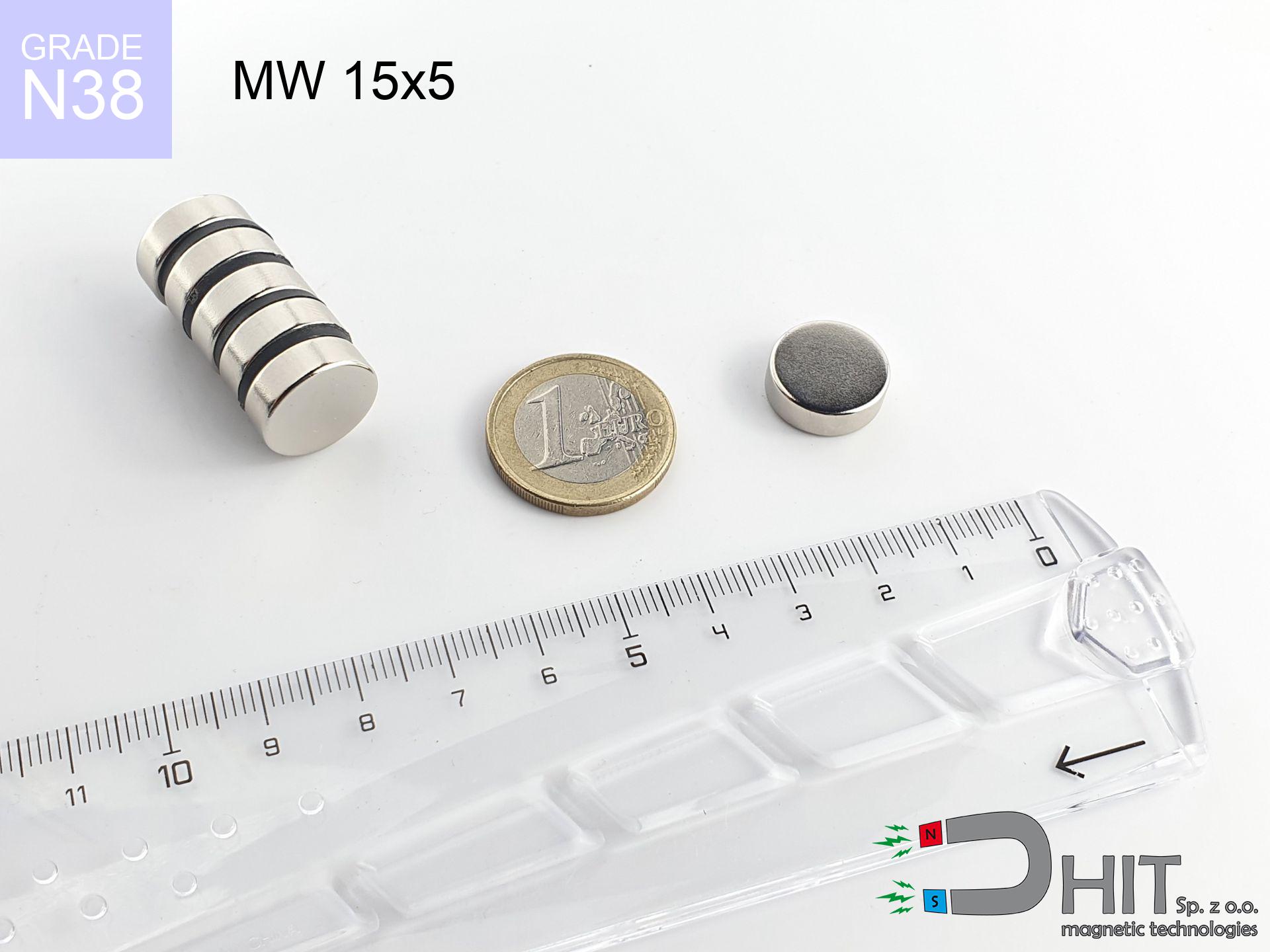
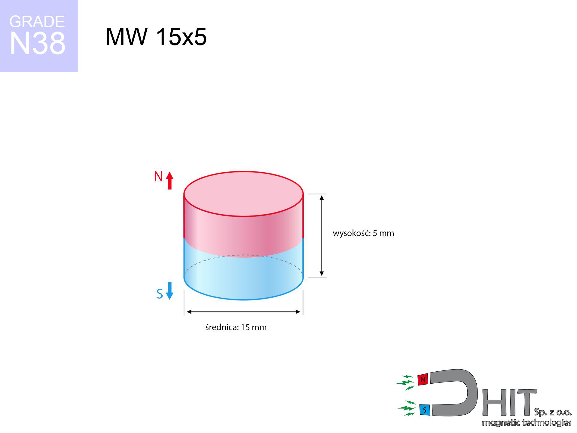
MW 15x5 / N38 - cylindrical magnet
cylindrical magnet
Catalog no 010031
GTIN/EAN: 5906301810308
Diameter Ø
15 mm [±0,1 mm]
Height
5 mm [±0,1 mm]
Weight
6.63 g
Magnetization Direction
↑ axial
Load capacity
5.39 kg / 52.83 N
Magnetic Induction
343.70 mT / 3437 Gs
Coating
[NiCuNi] Nickel
3.20 ZŁ with VAT / pcs + price for transport
2.60 ZŁ net + 23% VAT / pcs
bulk discounts:
Need more?
Pick up the phone and ask
+48 22 499 98 98
or contact us through
our online form
our website.
Parameters and structure of a magnet can be checked using our
force calculator.
Orders placed before 14:00 will be shipped the same business day.
Technical details - MW 15x5 / N38 - cylindrical magnet
Specification / characteristics - MW 15x5 / N38 - cylindrical magnet
| properties | values |
|---|---|
| Cat. no. | 010031 |
| GTIN/EAN | 5906301810308 |
| Production/Distribution | Dhit sp. z o.o. |
| Country of origin | Poland / China / Germany |
| Customs code | 85059029 |
| Diameter Ø | 15 mm [±0,1 mm] |
| Height | 5 mm [±0,1 mm] |
| Weight | 6.63 g |
| Magnetization Direction | ↑ axial |
| Load capacity ~ ? | 5.39 kg / 52.83 N |
| Magnetic Induction ~ ? | 343.70 mT / 3437 Gs |
| Coating | [NiCuNi] Nickel |
| Manufacturing Tolerance | ±0.1 mm |
Magnetic properties of material N38
| properties | values | units |
|---|---|---|
| remenance Br [min. - max.] ? | 12.2-12.6 | kGs |
| remenance Br [min. - max.] ? | 1220-1260 | mT |
| coercivity bHc ? | 10.8-11.5 | kOe |
| coercivity bHc ? | 860-915 | kA/m |
| actual internal force iHc | ≥ 12 | kOe |
| actual internal force iHc | ≥ 955 | kA/m |
| energy density [min. - max.] ? | 36-38 | BH max MGOe |
| energy density [min. - max.] ? | 287-303 | BH max KJ/m |
| max. temperature ? | ≤ 80 | °C |
Physical properties of sintered neodymium magnets Nd2Fe14B at 20°C
| properties | values | units |
|---|---|---|
| Vickers hardness | ≥550 | Hv |
| Density | ≥7.4 | g/cm3 |
| Curie Temperature TC | 312 - 380 | °C |
| Curie Temperature TF | 593 - 716 | °F |
| Specific resistance | 150 | μΩ⋅cm |
| Bending strength | 250 | MPa |
| Compressive strength | 1000~1100 | MPa |
| Thermal expansion parallel (∥) to orientation (M) | (3-4) x 10-6 | °C-1 |
| Thermal expansion perpendicular (⊥) to orientation (M) | -(1-3) x 10-6 | °C-1 |
| Young's modulus | 1.7 x 10⁴ | kg/mm² |
Engineering simulation of the magnet - report
These values represent the outcome of a engineering calculation. Results rely on models for the material Nd2Fe14B. Operational performance might slightly differ from theoretical values. Please consider these calculations as a reference point when designing systems.
Table 1: Static force (pull vs distance) - characteristics
MW 15x5 / N38
| Distance (mm) | Induction (Gauss) / mT | Pull Force (kg/lbs/g/N) | Risk Status |
|---|---|---|---|
| 0 mm |
3436 Gs
343.6 mT
|
5.39 kg / 11.88 lbs
5390.0 g / 52.9 N
|
warning |
| 1 mm |
3054 Gs
305.4 mT
|
4.26 kg / 9.39 lbs
4258.2 g / 41.8 N
|
warning |
| 2 mm |
2633 Gs
263.3 mT
|
3.17 kg / 6.98 lbs
3165.4 g / 31.1 N
|
warning |
| 3 mm |
2221 Gs
222.1 mT
|
2.25 kg / 4.96 lbs
2251.5 g / 22.1 N
|
warning |
| 5 mm |
1521 Gs
152.1 mT
|
1.06 kg / 2.33 lbs
1056.2 g / 10.4 N
|
low risk |
| 10 mm |
585 Gs
58.5 mT
|
0.16 kg / 0.35 lbs
156.5 g / 1.5 N
|
low risk |
| 15 mm |
260 Gs
26.0 mT
|
0.03 kg / 0.07 lbs
30.8 g / 0.3 N
|
low risk |
| 20 mm |
133 Gs
13.3 mT
|
0.01 kg / 0.02 lbs
8.1 g / 0.1 N
|
low risk |
| 30 mm |
47 Gs
4.7 mT
|
0.00 kg / 0.00 lbs
1.0 g / 0.0 N
|
low risk |
| 50 mm |
12 Gs
1.2 mT
|
0.00 kg / 0.00 lbs
0.1 g / 0.0 N
|
low risk |
Table 2: Shear load (vertical surface)
MW 15x5 / N38
| Distance (mm) | Friction coefficient | Pull Force (kg/lbs/g/N) |
|---|---|---|
| 0 mm | Stal (~0.2) |
1.08 kg / 2.38 lbs
1078.0 g / 10.6 N
|
| 1 mm | Stal (~0.2) |
0.85 kg / 1.88 lbs
852.0 g / 8.4 N
|
| 2 mm | Stal (~0.2) |
0.63 kg / 1.40 lbs
634.0 g / 6.2 N
|
| 3 mm | Stal (~0.2) |
0.45 kg / 0.99 lbs
450.0 g / 4.4 N
|
| 5 mm | Stal (~0.2) |
0.21 kg / 0.47 lbs
212.0 g / 2.1 N
|
| 10 mm | Stal (~0.2) |
0.03 kg / 0.07 lbs
32.0 g / 0.3 N
|
| 15 mm | Stal (~0.2) |
0.01 kg / 0.01 lbs
6.0 g / 0.1 N
|
| 20 mm | Stal (~0.2) |
0.00 kg / 0.00 lbs
2.0 g / 0.0 N
|
| 30 mm | Stal (~0.2) |
0.00 kg / 0.00 lbs
0.0 g / 0.0 N
|
| 50 mm | Stal (~0.2) |
0.00 kg / 0.00 lbs
0.0 g / 0.0 N
|
Table 3: Wall mounting (sliding) - behavior on slippery surfaces
MW 15x5 / N38
| Surface type | Friction coefficient / % Mocy | Max load (kg/lbs/g/N) |
|---|---|---|
| Raw steel |
µ = 0.3
30% Nominalnej Siły
|
1.62 kg / 3.56 lbs
1617.0 g / 15.9 N
|
| Painted steel (standard) |
µ = 0.2
20% Nominalnej Siły
|
1.08 kg / 2.38 lbs
1078.0 g / 10.6 N
|
| Oily/slippery steel |
µ = 0.1
10% Nominalnej Siły
|
0.54 kg / 1.19 lbs
539.0 g / 5.3 N
|
| Magnet with anti-slip rubber |
µ = 0.5
50% Nominalnej Siły
|
2.70 kg / 5.94 lbs
2695.0 g / 26.4 N
|
Table 4: Steel thickness (substrate influence) - power losses
MW 15x5 / N38
| Steel thickness (mm) | % power | Real pull force (kg/lbs/g/N) |
|---|---|---|
| 0.5 mm |
|
0.54 kg / 1.19 lbs
539.0 g / 5.3 N
|
| 1 mm |
|
1.35 kg / 2.97 lbs
1347.5 g / 13.2 N
|
| 2 mm |
|
2.70 kg / 5.94 lbs
2695.0 g / 26.4 N
|
| 3 mm |
|
4.04 kg / 8.91 lbs
4042.5 g / 39.7 N
|
| 5 mm |
|
5.39 kg / 11.88 lbs
5390.0 g / 52.9 N
|
| 10 mm |
|
5.39 kg / 11.88 lbs
5390.0 g / 52.9 N
|
| 11 mm |
|
5.39 kg / 11.88 lbs
5390.0 g / 52.9 N
|
| 12 mm |
|
5.39 kg / 11.88 lbs
5390.0 g / 52.9 N
|
Table 5: Thermal resistance (material behavior) - resistance threshold
MW 15x5 / N38
| Ambient temp. (°C) | Power loss | Remaining pull (kg/lbs/g/N) | Status |
|---|---|---|---|
| 20 °C | 0.0% |
5.39 kg / 11.88 lbs
5390.0 g / 52.9 N
|
OK |
| 40 °C | -2.2% |
5.27 kg / 11.62 lbs
5271.4 g / 51.7 N
|
OK |
| 60 °C | -4.4% |
5.15 kg / 11.36 lbs
5152.8 g / 50.5 N
|
|
| 80 °C | -6.6% |
5.03 kg / 11.10 lbs
5034.3 g / 49.4 N
|
|
| 100 °C | -28.8% |
3.84 kg / 8.46 lbs
3837.7 g / 37.6 N
|
Table 6: Magnet-Magnet interaction (attraction) - forces in the system
MW 15x5 / N38
| Gap (mm) | Attraction (kg/lbs) (N-S) | Lateral Force (kg/lbs/g/N) | Repulsion (kg/lbs) (N-N) |
|---|---|---|---|
| 0 mm |
12.86 kg / 28.35 lbs
4 954 Gs
|
1.93 kg / 4.25 lbs
1929 g / 18.9 N
|
N/A |
| 1 mm |
11.54 kg / 25.43 lbs
6 508 Gs
|
1.73 kg / 3.81 lbs
1730 g / 17.0 N
|
10.38 kg / 22.89 lbs
~0 Gs
|
| 2 mm |
10.16 kg / 22.40 lbs
6 107 Gs
|
1.52 kg / 3.36 lbs
1524 g / 14.9 N
|
9.14 kg / 20.16 lbs
~0 Gs
|
| 3 mm |
8.82 kg / 19.44 lbs
5 689 Gs
|
1.32 kg / 2.92 lbs
1322 g / 13.0 N
|
7.93 kg / 17.49 lbs
~0 Gs
|
| 5 mm |
6.40 kg / 14.11 lbs
4 847 Gs
|
0.96 kg / 2.12 lbs
960 g / 9.4 N
|
5.76 kg / 12.70 lbs
~0 Gs
|
| 10 mm |
2.52 kg / 5.56 lbs
3 042 Gs
|
0.38 kg / 0.83 lbs
378 g / 3.7 N
|
2.27 kg / 5.00 lbs
~0 Gs
|
| 20 mm |
0.37 kg / 0.82 lbs
1 171 Gs
|
0.06 kg / 0.12 lbs
56 g / 0.5 N
|
0.34 kg / 0.74 lbs
~0 Gs
|
| 50 mm |
0.01 kg / 0.01 lbs
153 Gs
|
0.00 kg / 0.00 lbs
1 g / 0.0 N
|
0.00 kg / 0.00 lbs
~0 Gs
|
| 60 mm |
0.00 kg / 0.01 lbs
95 Gs
|
0.00 kg / 0.00 lbs
0 g / 0.0 N
|
0.00 kg / 0.00 lbs
~0 Gs
|
| 70 mm |
0.00 kg / 0.00 lbs
63 Gs
|
0.00 kg / 0.00 lbs
0 g / 0.0 N
|
0.00 kg / 0.00 lbs
~0 Gs
|
| 80 mm |
0.00 kg / 0.00 lbs
44 Gs
|
0.00 kg / 0.00 lbs
0 g / 0.0 N
|
0.00 kg / 0.00 lbs
~0 Gs
|
| 90 mm |
0.00 kg / 0.00 lbs
32 Gs
|
0.00 kg / 0.00 lbs
0 g / 0.0 N
|
0.00 kg / 0.00 lbs
~0 Gs
|
| 100 mm |
0.00 kg / 0.00 lbs
23 Gs
|
0.00 kg / 0.00 lbs
0 g / 0.0 N
|
0.00 kg / 0.00 lbs
~0 Gs
|
Table 7: Protective zones (electronics) - precautionary measures
MW 15x5 / N38
| Object / Device | Limit (Gauss) / mT | Safe distance |
|---|---|---|
| Pacemaker | 5 Gs (0.5 mT) | 7.0 cm |
| Hearing aid | 10 Gs (1.0 mT) | 5.5 cm |
| Timepiece | 20 Gs (2.0 mT) | 4.5 cm |
| Phone / Smartphone | 40 Gs (4.0 mT) | 3.5 cm |
| Car key | 50 Gs (5.0 mT) | 3.0 cm |
| Payment card | 400 Gs (40.0 mT) | 1.5 cm |
| HDD hard drive | 600 Gs (60.0 mT) | 1.0 cm |
Table 8: Impact energy (kinetic energy) - warning
MW 15x5 / N38
| Start from (mm) | Speed (km/h) | Energy (J) | Predicted outcome |
|---|---|---|---|
| 10 mm |
29.27 km/h
(8.13 m/s)
|
0.22 J | |
| 30 mm |
49.81 km/h
(13.84 m/s)
|
0.63 J | |
| 50 mm |
64.30 km/h
(17.86 m/s)
|
1.06 J | |
| 100 mm |
90.93 km/h
(25.26 m/s)
|
2.12 J |
Table 9: Anti-corrosion coating durability
MW 15x5 / N38
| Technical parameter | Value / Description |
|---|---|
| Coating type | [NiCuNi] Nickel |
| Layer structure | Nickel - Copper - Nickel |
| Layer thickness | 10-20 µm |
| Salt spray test (SST) ? | 24 h |
| Recommended environment | Indoors only (dry) |
Table 10: Electrical data (Flux)
MW 15x5 / N38
| Parameter | Value | SI Unit / Description |
|---|---|---|
| Magnetic Flux | 6 428 Mx | 64.3 µWb |
| Pc Coefficient | 0.44 | Low (Flat) |
Table 11: Underwater work (magnet fishing)
MW 15x5 / N38
| Environment | Effective steel pull | Effect |
|---|---|---|
| Air (land) | 5.39 kg | Standard |
| Water (riverbed) |
6.17 kg
(+0.78 kg buoyancy gain)
|
+14.5% |
1. Wall mount (shear)
*Caution: On a vertical wall, the magnet retains only ~20% of its perpendicular strength.
2. Efficiency vs thickness
*Thin metal sheet (e.g. computer case) significantly limits the holding force.
3. Power loss vs temp
*For N38 material, the critical limit is 80°C.
4. Demagnetization curve and operating point (B-H)
chart generated for the permeance coefficient Pc (Permeance Coefficient) = 0.44
This simulation demonstrates the magnetic stability of the selected magnet under specific geometric conditions. The solid red line represents the demagnetization curve (material potential), while the dashed blue line is the load line based on the magnet's geometry. The Pc (Permeance Coefficient), also known as the load line slope, is a dimensionless value that describes the relationship between the magnet's shape and its magnetic stability. The intersection of these two lines (the black dot) is the operating point — it determines the actual magnetic flux density generated by the magnet in this specific configuration. A higher Pc value means the magnet is more 'slender' (tall relative to its area), resulting in a higher operating point and better resistance to irreversible demagnetization caused by external fields or temperature. A value of 0.42 is relatively low (typical for flat magnets), meaning the operating point is closer to the 'knee' of the curve — caution is advised when operating at temperatures near the maximum limit to avoid strength loss.
Material specification
| iron (Fe) | 64% – 68% |
| neodymium (Nd) | 29% – 32% |
| boron (B) | 1.1% – 1.2% |
| dysprosium (Dy) | 0.5% – 2.0% |
| coating (Ni-Cu-Ni) | < 0.05% |
Ecology and recycling (GPSR)
| recyclability (EoL) | 100% |
| recycled raw materials | ~10% (pre-cons) |
| carbon footprint | low / zredukowany |
| waste code (EWC) | 16 02 16 |
View more proposals
![BM 380x180x70 [4x M8] - magnetic beam](https://cdn3.dhit.pl/graphics/products/bm-380x180x70-4x-m8-wex.jpg "BM 380x180x70 [4x M8] - magnetic beam")
![SM 32x350 [2xM8] / N42 - magnetic separator](https://cdn3.dhit.pl/graphics/products/sm-32x350-2xm8-nih.jpg "SM 32x350 [2xM8] / N42 - magnetic separator")
![UMGGZ 22x6 [M4] GZ / N38 - rubber magnetic holder external thread](https://cdn3.dhit.pl/graphics/products/umg-22x6-m4-gz-hiw.jpg "UMGGZ 22x6 [M4] GZ / N38 - rubber magnetic holder external thread")

Strengths and weaknesses of neodymium magnets.
Benefits
- Their magnetic field remains stable, and after around 10 years it drops only by ~1% (according to research),
- Neodymium magnets are extremely resistant to magnetic field loss caused by external magnetic fields,
- By applying a smooth layer of nickel, the element presents an nice look,
- Magnets possess very high magnetic induction on the active area,
- Due to their durability and thermal resistance, neodymium magnets are capable of operate (depending on the shape) even at high temperatures reaching 230°C or more...
- Thanks to freedom in constructing and the capacity to modify to individual projects,
- Significant place in advanced technology sectors – they find application in data components, electric drive systems, medical devices, as well as modern systems.
- Compactness – despite small sizes they provide effective action, making them ideal for precision applications
Cons
- At very strong impacts they can crack, therefore we recommend placing them in steel cases. A metal housing provides additional protection against damage and increases the magnet's durability.
- When exposed to high temperature, neodymium magnets experience a drop in power. Often, when the temperature exceeds 80°C, their power decreases (depending on the size, as well as shape of the magnet). For those who need magnets for extreme conditions, we offer [AH] versions withstanding up to 230°C
- They rust in a humid environment - during use outdoors we suggest using waterproof magnets e.g. in rubber, plastic
- Due to limitations in realizing nuts and complicated forms in magnets, we propose using casing - magnetic holder.
- Health risk related to microscopic parts of magnets pose a threat, when accidentally swallowed, which gains importance in the context of child safety. Additionally, small components of these devices are able to complicate diagnosis medical after entering the body.
- High unit price – neodymium magnets are more expensive than other types of magnets (e.g. ferrite), which hinders application in large quantities
Lifting parameters
Magnetic strength at its maximum – what contributes to it?
- with the application of a yoke made of special test steel, ensuring full magnetic saturation
- possessing a massiveness of minimum 10 mm to ensure full flux closure
- with a surface cleaned and smooth
- without any clearance between the magnet and steel
- under vertical force direction (90-degree angle)
- at room temperature
Lifting capacity in real conditions – factors
- Gap (between the magnet and the plate), because even a microscopic distance (e.g. 0.5 mm) can cause a decrease in force by up to 50% (this also applies to varnish, corrosion or debris).
- Load vector – highest force is obtained only during perpendicular pulling. The resistance to sliding of the magnet along the plate is typically several times lower (approx. 1/5 of the lifting capacity).
- Steel thickness – insufficiently thick steel does not close the flux, causing part of the flux to be lost into the air.
- Steel type – mild steel attracts best. Higher carbon content reduce magnetic permeability and lifting capacity.
- Surface condition – smooth surfaces ensure maximum contact, which improves force. Rough surfaces reduce efficiency.
- Thermal environment – temperature increase results in weakening of induction. Check the maximum operating temperature for a given model.
Lifting capacity testing was carried out on a smooth plate of suitable thickness, under a perpendicular pulling force, whereas under parallel forces the load capacity is reduced by as much as 75%. In addition, even a minimal clearance between the magnet’s surface and the plate decreases the load capacity.
Safe handling of neodymium magnets
Beware of splinters
Despite the nickel coating, neodymium is brittle and not impact-resistant. Avoid impacts, as the magnet may shatter into hazardous fragments.
Allergic reactions
Certain individuals have a sensitization to Ni, which is the typical protective layer for NdFeB magnets. Prolonged contact may cause skin redness. We strongly advise wear safety gloves.
Safe operation
Use magnets with awareness. Their huge power can shock even experienced users. Stay alert and do not underestimate their power.
Bone fractures
Large magnets can smash fingers in a fraction of a second. Under no circumstances put your hand betwixt two strong magnets.
Heat warning
Avoid heat. Neodymium magnets are sensitive to temperature. If you require operation above 80°C, look for special high-temperature series (H, SH, UH).
Keep away from electronics
Navigation devices and smartphones are highly sensitive to magnetic fields. Direct contact with a powerful NdFeB magnet can permanently damage the sensors in your phone.
Dust is flammable
Fire warning: Neodymium dust is explosive. Do not process magnets without safety gear as this risks ignition.
Electronic devices
Powerful magnetic fields can erase data on credit cards, HDDs, and storage devices. Stay away of min. 10 cm.
Implant safety
Warning for patients: Strong magnetic fields disrupt medical devices. Maintain minimum 30 cm distance or ask another person to handle the magnets.
Swallowing risk
These products are not toys. Swallowing a few magnets may result in them attracting across intestines, which constitutes a direct threat to life and requires urgent medical intervention.
Tabela kosztu i czasu dostawy
Płatność przed wysyłką:

GLS kurier
Przesyłka będzie u Ciebie za 2-3 dni
14.99 ZŁ

InPost Paczkomaty 24/7
Przesyłka będzie u Ciebie za 1-2 dni
12.30 ZŁ
Płatność przy odbiorze (pobranie):
GLS kurier
Przesyłka będzie u Ciebie za 1-2 dni
23.00 ZŁ
Rate the product
Your rating