
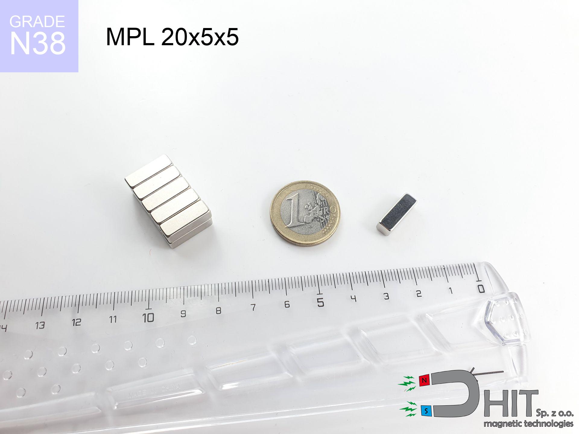
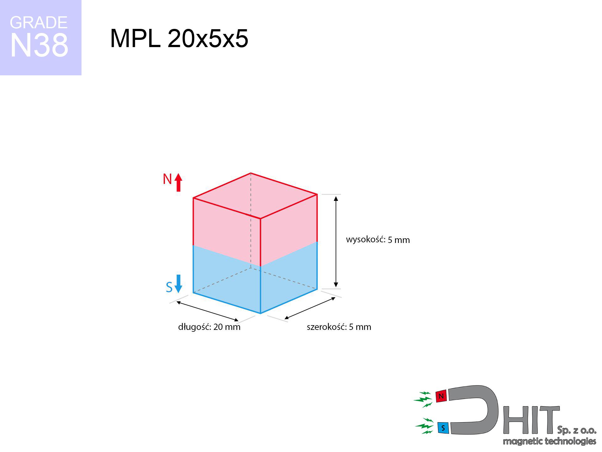
MPL 20x5x5 / N38 - lamellar magnet
lamellar magnet
Catalog no 020132
GTIN/EAN: 5906301811381
length
20 mm [±0,1 mm]
Width
5 mm [±0,1 mm]
Height
5 mm [±0,1 mm]
Weight
3.75 g
Magnetization Direction
↑ axial
Load capacity
4.42 kg / 43.32 N
Magnetic Induction
456.78 mT / 4568 Gs
Coating
[NiCuNi] Nickel
2.76 ZŁ with VAT / pcs + price for transport
2.24 ZŁ net + 23% VAT / pcs
bulk discounts:
Need more?
Call us
+48 888 99 98 98
or drop us a message via
inquiry form
our website.
Lifting power as well as form of neodymium magnets can be reviewed using our
modular calculator.
Orders submitted before 14:00 will be dispatched today!
Product card - MPL 20x5x5 / N38 - lamellar magnet
Specification / characteristics - MPL 20x5x5 / N38 - lamellar magnet
| properties | values |
|---|---|
| Cat. no. | 020132 |
| GTIN/EAN | 5906301811381 |
| Production/Distribution | Dhit sp. z o.o. |
| Country of origin | Poland / China / Germany |
| Customs code | 85059029 |
| length | 20 mm [±0,1 mm] |
| Width | 5 mm [±0,1 mm] |
| Height | 5 mm [±0,1 mm] |
| Weight | 3.75 g |
| Magnetization Direction | ↑ axial |
| Load capacity ~ ? | 4.42 kg / 43.32 N |
| Magnetic Induction ~ ? | 456.78 mT / 4568 Gs |
| Coating | [NiCuNi] Nickel |
| Manufacturing Tolerance | ±0.1 mm |
Magnetic properties of material N38
| properties | values | units |
|---|---|---|
| remenance Br [min. - max.] ? | 12.2-12.6 | kGs |
| remenance Br [min. - max.] ? | 1220-1260 | mT |
| coercivity bHc ? | 10.8-11.5 | kOe |
| coercivity bHc ? | 860-915 | kA/m |
| actual internal force iHc | ≥ 12 | kOe |
| actual internal force iHc | ≥ 955 | kA/m |
| energy density [min. - max.] ? | 36-38 | BH max MGOe |
| energy density [min. - max.] ? | 287-303 | BH max KJ/m |
| max. temperature ? | ≤ 80 | °C |
Physical properties of sintered neodymium magnets Nd2Fe14B at 20°C
| properties | values | units |
|---|---|---|
| Vickers hardness | ≥550 | Hv |
| Density | ≥7.4 | g/cm3 |
| Curie Temperature TC | 312 - 380 | °C |
| Curie Temperature TF | 593 - 716 | °F |
| Specific resistance | 150 | μΩ⋅cm |
| Bending strength | 250 | MPa |
| Compressive strength | 1000~1100 | MPa |
| Thermal expansion parallel (∥) to orientation (M) | (3-4) x 10-6 | °C-1 |
| Thermal expansion perpendicular (⊥) to orientation (M) | -(1-3) x 10-6 | °C-1 |
| Young's modulus | 1.7 x 10⁴ | kg/mm² |
Physical simulation of the product - technical parameters
Presented data represent the result of a engineering analysis. Results were calculated on algorithms for the class Nd2Fe14B. Actual conditions might slightly deviate from the simulation results. Treat these data as a supplementary guide for designers.
Table 1: Static force (force vs gap) - characteristics
MPL 20x5x5 / N38
| Distance (mm) | Induction (Gauss) / mT | Pull Force (kg/lbs/g/N) | Risk Status |
|---|---|---|---|
| 0 mm |
4563 Gs
456.3 mT
|
4.42 kg / 9.74 lbs
4420.0 g / 43.4 N
|
warning |
| 1 mm |
3323 Gs
332.3 mT
|
2.34 kg / 5.17 lbs
2344.7 g / 23.0 N
|
warning |
| 2 mm |
2341 Gs
234.1 mT
|
1.16 kg / 2.56 lbs
1163.0 g / 11.4 N
|
weak grip |
| 3 mm |
1678 Gs
167.8 mT
|
0.60 kg / 1.32 lbs
597.4 g / 5.9 N
|
weak grip |
| 5 mm |
944 Gs
94.4 mT
|
0.19 kg / 0.42 lbs
189.2 g / 1.9 N
|
weak grip |
| 10 mm |
320 Gs
32.0 mT
|
0.02 kg / 0.05 lbs
21.7 g / 0.2 N
|
weak grip |
| 15 mm |
141 Gs
14.1 mT
|
0.00 kg / 0.01 lbs
4.2 g / 0.0 N
|
weak grip |
| 20 mm |
73 Gs
7.3 mT
|
0.00 kg / 0.00 lbs
1.1 g / 0.0 N
|
weak grip |
| 30 mm |
26 Gs
2.6 mT
|
0.00 kg / 0.00 lbs
0.1 g / 0.0 N
|
weak grip |
| 50 mm |
7 Gs
0.7 mT
|
0.00 kg / 0.00 lbs
0.0 g / 0.0 N
|
weak grip |
Table 2: Shear force (vertical surface)
MPL 20x5x5 / N38
| Distance (mm) | Friction coefficient | Pull Force (kg/lbs/g/N) |
|---|---|---|
| 0 mm | Stal (~0.2) |
0.88 kg / 1.95 lbs
884.0 g / 8.7 N
|
| 1 mm | Stal (~0.2) |
0.47 kg / 1.03 lbs
468.0 g / 4.6 N
|
| 2 mm | Stal (~0.2) |
0.23 kg / 0.51 lbs
232.0 g / 2.3 N
|
| 3 mm | Stal (~0.2) |
0.12 kg / 0.26 lbs
120.0 g / 1.2 N
|
| 5 mm | Stal (~0.2) |
0.04 kg / 0.08 lbs
38.0 g / 0.4 N
|
| 10 mm | Stal (~0.2) |
0.00 kg / 0.01 lbs
4.0 g / 0.0 N
|
| 15 mm | Stal (~0.2) |
0.00 kg / 0.00 lbs
0.0 g / 0.0 N
|
| 20 mm | Stal (~0.2) |
0.00 kg / 0.00 lbs
0.0 g / 0.0 N
|
| 30 mm | Stal (~0.2) |
0.00 kg / 0.00 lbs
0.0 g / 0.0 N
|
| 50 mm | Stal (~0.2) |
0.00 kg / 0.00 lbs
0.0 g / 0.0 N
|
Table 3: Wall mounting (sliding) - behavior on slippery surfaces
MPL 20x5x5 / N38
| Surface type | Friction coefficient / % Mocy | Max load (kg/lbs/g/N) |
|---|---|---|
| Raw steel |
µ = 0.3
30% Nominalnej Siły
|
1.33 kg / 2.92 lbs
1326.0 g / 13.0 N
|
| Painted steel (standard) |
µ = 0.2
20% Nominalnej Siły
|
0.88 kg / 1.95 lbs
884.0 g / 8.7 N
|
| Oily/slippery steel |
µ = 0.1
10% Nominalnej Siły
|
0.44 kg / 0.97 lbs
442.0 g / 4.3 N
|
| Magnet with anti-slip rubber |
µ = 0.5
50% Nominalnej Siły
|
2.21 kg / 4.87 lbs
2210.0 g / 21.7 N
|
Table 4: Material efficiency (saturation) - sheet metal selection
MPL 20x5x5 / N38
| Steel thickness (mm) | % power | Real pull force (kg/lbs/g/N) |
|---|---|---|
| 0.5 mm |
|
0.44 kg / 0.97 lbs
442.0 g / 4.3 N
|
| 1 mm |
|
1.11 kg / 2.44 lbs
1105.0 g / 10.8 N
|
| 2 mm |
|
2.21 kg / 4.87 lbs
2210.0 g / 21.7 N
|
| 3 mm |
|
3.32 kg / 7.31 lbs
3315.0 g / 32.5 N
|
| 5 mm |
|
4.42 kg / 9.74 lbs
4420.0 g / 43.4 N
|
| 10 mm |
|
4.42 kg / 9.74 lbs
4420.0 g / 43.4 N
|
| 11 mm |
|
4.42 kg / 9.74 lbs
4420.0 g / 43.4 N
|
| 12 mm |
|
4.42 kg / 9.74 lbs
4420.0 g / 43.4 N
|
Table 5: Working in heat (material behavior) - power drop
MPL 20x5x5 / N38
| Ambient temp. (°C) | Power loss | Remaining pull (kg/lbs/g/N) | Status |
|---|---|---|---|
| 20 °C | 0.0% |
4.42 kg / 9.74 lbs
4420.0 g / 43.4 N
|
OK |
| 40 °C | -2.2% |
4.32 kg / 9.53 lbs
4322.8 g / 42.4 N
|
OK |
| 60 °C | -4.4% |
4.23 kg / 9.32 lbs
4225.5 g / 41.5 N
|
|
| 80 °C | -6.6% |
4.13 kg / 9.10 lbs
4128.3 g / 40.5 N
|
|
| 100 °C | -28.8% |
3.15 kg / 6.94 lbs
3147.0 g / 30.9 N
|
Table 6: Two magnets (attraction) - field collision
MPL 20x5x5 / N38
| Gap (mm) | Attraction (kg/lbs) (N-S) | Shear Force (kg/lbs/g/N) | Repulsion (kg/lbs) (N-N) |
|---|---|---|---|
| 0 mm |
12.84 kg / 28.30 lbs
5 504 Gs
|
1.93 kg / 4.24 lbs
1925 g / 18.9 N
|
N/A |
| 1 mm |
9.53 kg / 21.01 lbs
7 864 Gs
|
1.43 kg / 3.15 lbs
1430 g / 14.0 N
|
8.58 kg / 18.91 lbs
~0 Gs
|
| 2 mm |
6.81 kg / 15.01 lbs
6 647 Gs
|
1.02 kg / 2.25 lbs
1021 g / 10.0 N
|
6.13 kg / 13.51 lbs
~0 Gs
|
| 3 mm |
4.79 kg / 10.57 lbs
5 577 Gs
|
0.72 kg / 1.59 lbs
719 g / 7.1 N
|
4.31 kg / 9.51 lbs
~0 Gs
|
| 5 mm |
2.40 kg / 5.30 lbs
3 949 Gs
|
0.36 kg / 0.79 lbs
360 g / 3.5 N
|
2.16 kg / 4.77 lbs
~0 Gs
|
| 10 mm |
0.55 kg / 1.21 lbs
1 888 Gs
|
0.08 kg / 0.18 lbs
82 g / 0.8 N
|
0.49 kg / 1.09 lbs
~0 Gs
|
| 20 mm |
0.06 kg / 0.14 lbs
640 Gs
|
0.01 kg / 0.02 lbs
9 g / 0.1 N
|
0.06 kg / 0.13 lbs
~0 Gs
|
| 50 mm |
0.00 kg / 0.00 lbs
84 Gs
|
0.00 kg / 0.00 lbs
0 g / 0.0 N
|
0.00 kg / 0.00 lbs
~0 Gs
|
| 60 mm |
0.00 kg / 0.00 lbs
53 Gs
|
0.00 kg / 0.00 lbs
0 g / 0.0 N
|
0.00 kg / 0.00 lbs
~0 Gs
|
| 70 mm |
0.00 kg / 0.00 lbs
35 Gs
|
0.00 kg / 0.00 lbs
0 g / 0.0 N
|
0.00 kg / 0.00 lbs
~0 Gs
|
| 80 mm |
0.00 kg / 0.00 lbs
24 Gs
|
0.00 kg / 0.00 lbs
0 g / 0.0 N
|
0.00 kg / 0.00 lbs
~0 Gs
|
| 90 mm |
0.00 kg / 0.00 lbs
18 Gs
|
0.00 kg / 0.00 lbs
0 g / 0.0 N
|
0.00 kg / 0.00 lbs
~0 Gs
|
| 100 mm |
0.00 kg / 0.00 lbs
13 Gs
|
0.00 kg / 0.00 lbs
0 g / 0.0 N
|
0.00 kg / 0.00 lbs
~0 Gs
|
Table 7: Safety (HSE) (electronics) - warnings
MPL 20x5x5 / N38
| Object / Device | Limit (Gauss) / mT | Safe distance |
|---|---|---|
| Pacemaker | 5 Gs (0.5 mT) | 6.0 cm |
| Hearing aid | 10 Gs (1.0 mT) | 4.5 cm |
| Mechanical watch | 20 Gs (2.0 mT) | 3.5 cm |
| Mobile device | 40 Gs (4.0 mT) | 3.0 cm |
| Car key | 50 Gs (5.0 mT) | 2.5 cm |
| Payment card | 400 Gs (40.0 mT) | 1.0 cm |
| HDD hard drive | 600 Gs (60.0 mT) | 1.0 cm |
Table 8: Dynamics (cracking risk) - collision effects
MPL 20x5x5 / N38
| Start from (mm) | Speed (km/h) | Energy (J) | Predicted outcome |
|---|---|---|---|
| 10 mm |
34.73 km/h
(9.65 m/s)
|
0.17 J | |
| 30 mm |
59.97 km/h
(16.66 m/s)
|
0.52 J | |
| 50 mm |
77.42 km/h
(21.51 m/s)
|
0.87 J | |
| 100 mm |
109.49 km/h
(30.41 m/s)
|
1.73 J |
Table 9: Corrosion resistance
MPL 20x5x5 / N38
| Technical parameter | Value / Description |
|---|---|
| Coating type | [NiCuNi] Nickel |
| Layer structure | Nickel - Copper - Nickel |
| Layer thickness | 10-20 µm |
| Salt spray test (SST) ? | 24 h |
| Recommended environment | Indoors only (dry) |
Table 10: Construction data (Flux)
MPL 20x5x5 / N38
| Parameter | Value | SI Unit / Description |
|---|---|---|
| Magnetic Flux | 4 204 Mx | 42.0 µWb |
| Pc Coefficient | 0.54 | Low (Flat) |
Table 11: Submerged application
MPL 20x5x5 / N38
| Environment | Effective steel pull | Effect |
|---|---|---|
| Air (land) | 4.42 kg | Standard |
| Water (riverbed) |
5.06 kg
(+0.64 kg buoyancy gain)
|
+14.5% |
1. Sliding resistance
*Caution: On a vertical surface, the magnet retains merely ~20% of its max power.
2. Steel saturation
*Thin steel (e.g. 0.5mm PC case) significantly limits the holding force.
3. Thermal stability
*For standard magnets, the safety limit is 80°C.
4. Demagnetization curve and operating point (B-H)
chart generated for the permeance coefficient Pc (Permeance Coefficient) = 0.54
This simulation demonstrates the magnetic stability of the selected magnet under specific geometric conditions. The solid red line represents the demagnetization curve (material potential), while the dashed blue line is the load line based on the magnet's geometry. The Pc (Permeance Coefficient), also known as the load line slope, is a dimensionless value that describes the relationship between the magnet's shape and its magnetic stability. The intersection of these two lines (the black dot) is the operating point — it determines the actual magnetic flux density generated by the magnet in this specific configuration. A higher Pc value means the magnet is more 'slender' (tall relative to its area), resulting in a higher operating point and better resistance to irreversible demagnetization caused by external fields or temperature. A value of 0.42 is relatively low (typical for flat magnets), meaning the operating point is closer to the 'knee' of the curve — caution is advised when operating at temperatures near the maximum limit to avoid strength loss.
Chemical composition
| iron (Fe) | 64% – 68% |
| neodymium (Nd) | 29% – 32% |
| boron (B) | 1.1% – 1.2% |
| dysprosium (Dy) | 0.5% – 2.0% |
| coating (Ni-Cu-Ni) | < 0.05% |
Ecology and recycling (GPSR)
| recyclability (EoL) | 100% |
| recycled raw materials | ~10% (pre-cons) |
| carbon footprint | low / zredukowany |
| waste code (EWC) | 16 02 16 |
Other offers


Pros and cons of Nd2Fe14B magnets.
Benefits
- They retain full power for almost 10 years – the loss is just ~1% (according to analyses),
- Magnets effectively resist against demagnetization caused by ambient magnetic noise,
- Thanks to the shiny finish, the layer of Ni-Cu-Ni, gold-plated, or silver gives an modern appearance,
- The surface of neodymium magnets generates a maximum magnetic field – this is a distinguishing feature,
- Neodymium magnets are characterized by very high magnetic induction on the magnet surface and can work (depending on the shape) even at a temperature of 230°C or more...
- Thanks to versatility in designing and the capacity to adapt to client solutions,
- Huge importance in modern industrial fields – they are used in HDD drives, drive modules, advanced medical instruments, and industrial machines.
- Compactness – despite small sizes they generate large force, making them ideal for precision applications
Disadvantages
- To avoid cracks upon strong impacts, we suggest using special steel holders. Such a solution protects the magnet and simultaneously increases its durability.
- Neodymium magnets demagnetize when exposed to high temperatures. After reaching 80°C, many of them experience permanent weakening of strength (a factor is the shape and dimensions of the magnet). We offer magnets specially adapted to work at temperatures up to 230°C marked [AH], which are extremely resistant to heat
- They oxidize in a humid environment. For use outdoors we suggest using waterproof magnets e.g. in rubber, plastic
- Limited ability of creating threads in the magnet and complicated forms - recommended is cover - magnet mounting.
- Possible danger resulting from small fragments of magnets are risky, if swallowed, which is particularly important in the context of child health protection. Furthermore, tiny parts of these magnets can be problematic in diagnostics medical in case of swallowing.
- With budget limitations the cost of neodymium magnets can be a barrier,
Lifting parameters
Maximum lifting capacity of the magnet – what affects it?
- on a block made of mild steel, effectively closing the magnetic field
- whose thickness is min. 10 mm
- with a plane perfectly flat
- with direct contact (without coatings)
- for force applied at a right angle (pull-off, not shear)
- at conditions approx. 20°C
Magnet lifting force in use – key factors
- Clearance – existence of foreign body (paint, dirt, air) acts as an insulator, which reduces power rapidly (even by 50% at 0.5 mm).
- Force direction – catalog parameter refers to pulling vertically. When applying parallel force, the magnet holds much less (often approx. 20-30% of maximum force).
- Steel thickness – too thin steel does not accept the full field, causing part of the flux to be lost into the air.
- Plate material – low-carbon steel gives the best results. Alloy steels decrease magnetic permeability and holding force.
- Surface condition – smooth surfaces ensure maximum contact, which improves field saturation. Uneven metal weaken the grip.
- Thermal factor – hot environment weakens magnetic field. Too high temperature can permanently damage the magnet.
Lifting capacity was determined by applying a steel plate with a smooth surface of suitable thickness (min. 20 mm), under perpendicular detachment force, whereas under parallel forces the load capacity is reduced by as much as 5 times. Additionally, even a slight gap between the magnet and the plate decreases the lifting capacity.
Safety rules for work with NdFeB magnets
Caution required
Handle magnets consciously. Their huge power can shock even professionals. Plan your moves and respect their force.
Adults only
These products are not suitable for play. Eating several magnets can lead to them pinching intestinal walls, which poses a critical condition and requires urgent medical intervention.
Threat to navigation
GPS units and mobile phones are highly sensitive to magnetic fields. Close proximity with a strong magnet can decalibrate the sensors in your phone.
Bodily injuries
Watch your fingers. Two large magnets will snap together immediately with a force of massive weight, destroying anything in their path. Be careful!
Beware of splinters
NdFeB magnets are ceramic materials, which means they are fragile like glass. Clashing of two magnets will cause them cracking into shards.
Thermal limits
Standard neodymium magnets (N-type) lose power when the temperature goes above 80°C. The loss of strength is permanent.
Allergy Warning
Medical facts indicate that the nickel plating (the usual finish) is a potent allergen. If you have an allergy, refrain from touching magnets with bare hands and opt for encased magnets.
Danger to pacemakers
People with a heart stimulator must keep an safe separation from magnets. The magnetism can disrupt the operation of the implant.
Electronic hazard
Do not bring magnets close to a purse, computer, or screen. The magnetic field can destroy these devices and wipe information from cards.
Do not drill into magnets
Drilling and cutting of neodymium magnets poses a fire hazard. Magnetic powder reacts violently with oxygen and is hard to extinguish.
Tabela kosztu i czasu dostawy
Płatność przed wysyłką:

GLS kurier
Przesyłka będzie u Ciebie za 2-3 dni
14.99 ZŁ

InPost Paczkomaty 24/7
Przesyłka będzie u Ciebie za 1-2 dni
12.30 ZŁ
Płatność przy odbiorze (pobranie):
GLS kurier
Przesyłka będzie u Ciebie za 1-2 dni
23.00 ZŁ
Rate the product
Your rating