
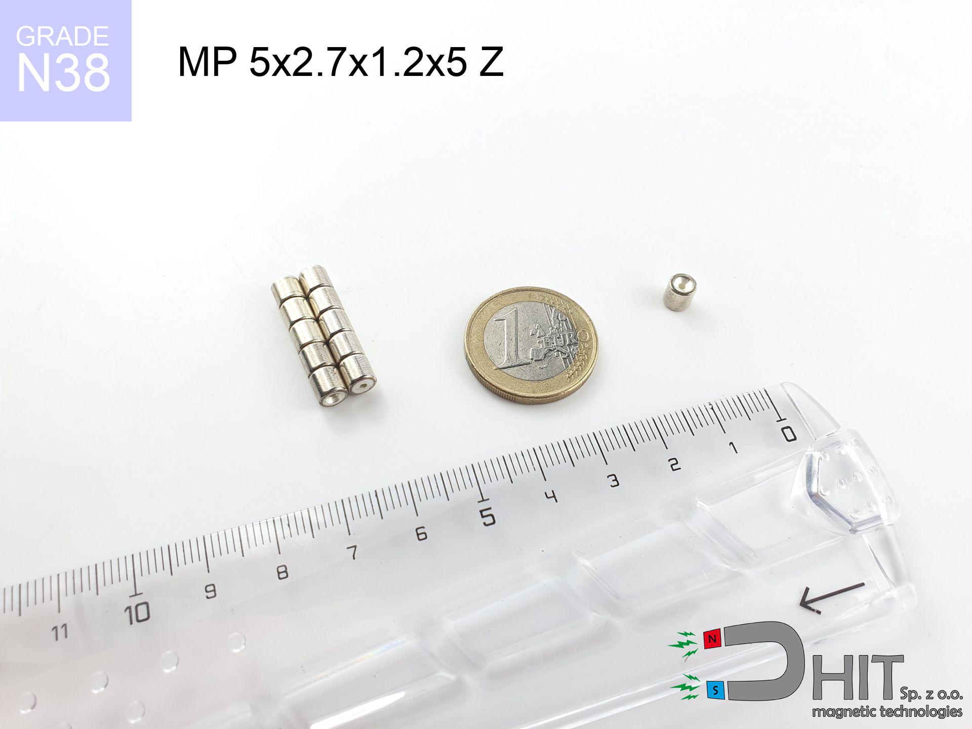
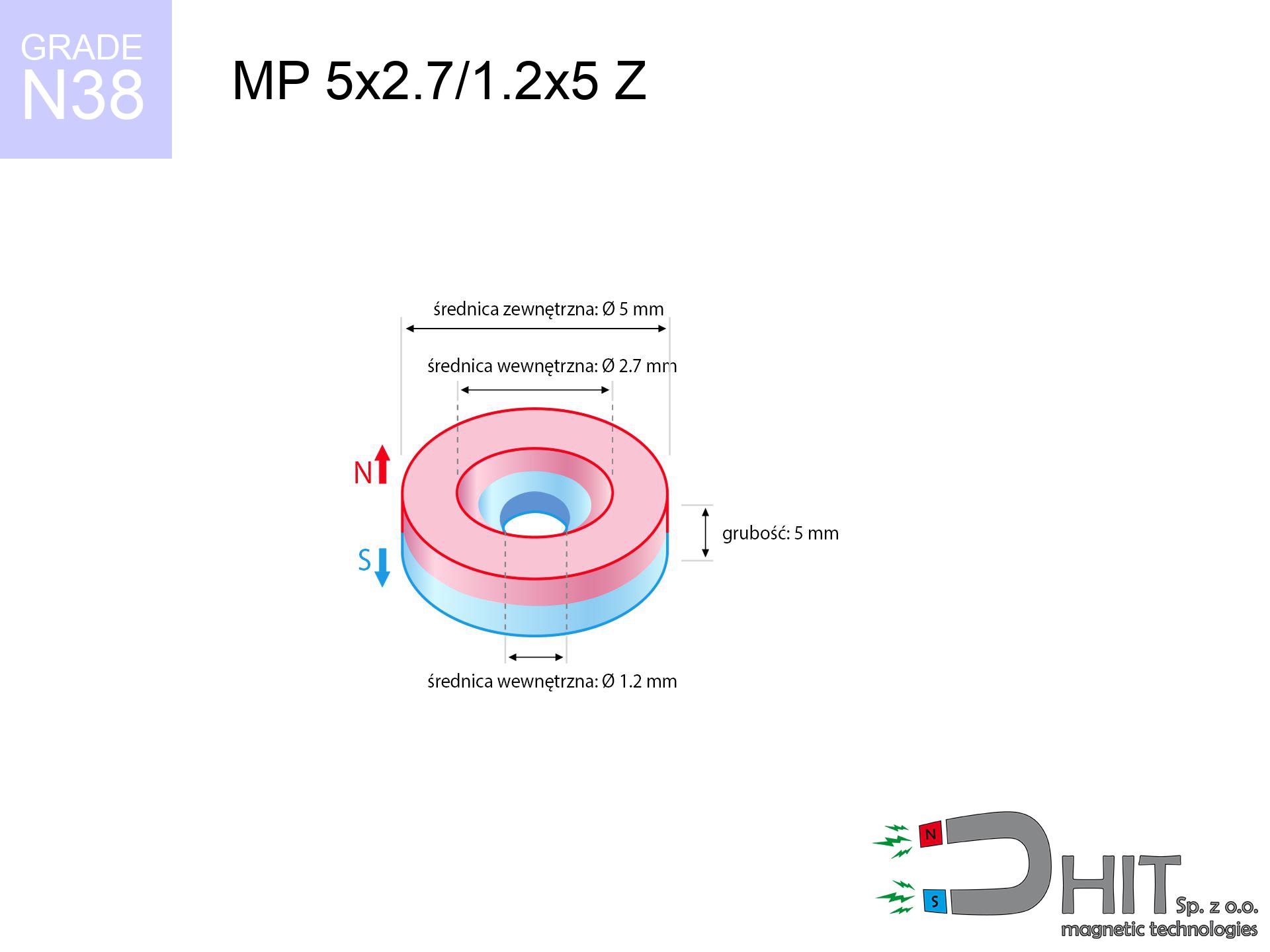
MP 5x2.7/1.2x5 Z / N38 - ring magnet
ring magnet
Catalog no 030203
GTIN/EAN: 5906301812203
Diameter
5 mm [±0,1 mm]
internal diameter Ø
2.7/1.2 mm [±0,1 mm]
Height
5 mm [±0,1 mm]
Weight
0.69 g
Magnetization Direction
↑ axial
Load capacity
0.75 kg / 7.31 N
Magnetic Induction
553.14 mT / 5531 Gs
Coating
[NiCuNi] Nickel
0.836 ZŁ with VAT / pcs + price for transport
0.680 ZŁ net + 23% VAT / pcs
bulk discounts:
Need more?
Call us
+48 22 499 98 98
alternatively send us a note through
contact form
our website.
Specifications and structure of a neodymium magnet can be verified on our
our magnetic calculator.
Orders placed before 14:00 will be shipped the same business day.
Technical - MP 5x2.7/1.2x5 Z / N38 - ring magnet
Specification / characteristics - MP 5x2.7/1.2x5 Z / N38 - ring magnet
| properties | values |
|---|---|
| Cat. no. | 030203 |
| GTIN/EAN | 5906301812203 |
| Production/Distribution | Dhit sp. z o.o. |
| Country of origin | Poland / China / Germany |
| Customs code | 85059029 |
| Diameter | 5 mm [±0,1 mm] |
| internal diameter Ø | 2.7/1.2 mm [±0,1 mm] |
| Height | 5 mm [±0,1 mm] |
| Weight | 0.69 g |
| Magnetization Direction | ↑ axial |
| Load capacity ~ ? | 0.75 kg / 7.31 N |
| Magnetic Induction ~ ? | 553.14 mT / 5531 Gs |
| Coating | [NiCuNi] Nickel |
| Manufacturing Tolerance | ±0.1 mm |
Magnetic properties of material N38
| properties | values | units |
|---|---|---|
| remenance Br [min. - max.] ? | 12.2-12.6 | kGs |
| remenance Br [min. - max.] ? | 1220-1260 | mT |
| coercivity bHc ? | 10.8-11.5 | kOe |
| coercivity bHc ? | 860-915 | kA/m |
| actual internal force iHc | ≥ 12 | kOe |
| actual internal force iHc | ≥ 955 | kA/m |
| energy density [min. - max.] ? | 36-38 | BH max MGOe |
| energy density [min. - max.] ? | 287-303 | BH max KJ/m |
| max. temperature ? | ≤ 80 | °C |
Physical properties of sintered neodymium magnets Nd2Fe14B at 20°C
| properties | values | units |
|---|---|---|
| Vickers hardness | ≥550 | Hv |
| Density | ≥7.4 | g/cm3 |
| Curie Temperature TC | 312 - 380 | °C |
| Curie Temperature TF | 593 - 716 | °F |
| Specific resistance | 150 | μΩ⋅cm |
| Bending strength | 250 | MPa |
| Compressive strength | 1000~1100 | MPa |
| Thermal expansion parallel (∥) to orientation (M) | (3-4) x 10-6 | °C-1 |
| Thermal expansion perpendicular (⊥) to orientation (M) | -(1-3) x 10-6 | °C-1 |
| Young's modulus | 1.7 x 10⁴ | kg/mm² |
Engineering analysis of the assembly - report
These information represent the outcome of a mathematical calculation. Values were calculated on models for the material Nd2Fe14B. Operational parameters may deviate from the simulation results. Use these calculations as a preliminary roadmap during assembly planning.
Table 1: Static pull force (pull vs gap) - interaction chart
MP 5x2.7/1.2x5 Z / N38
| Distance (mm) | Induction (Gauss) / mT | Pull Force (kg/lbs/g/N) | Risk Status |
|---|---|---|---|
| 0 mm |
5322 Gs
532.2 mT
|
0.75 kg / 1.65 pounds
750.0 g / 7.4 N
|
weak grip |
| 1 mm |
3295 Gs
329.5 mT
|
0.29 kg / 0.63 pounds
287.5 g / 2.8 N
|
weak grip |
| 2 mm |
1883 Gs
188.3 mT
|
0.09 kg / 0.21 pounds
93.9 g / 0.9 N
|
weak grip |
| 3 mm |
1098 Gs
109.8 mT
|
0.03 kg / 0.07 pounds
31.9 g / 0.3 N
|
weak grip |
| 5 mm |
440 Gs
44.0 mT
|
0.01 kg / 0.01 pounds
5.1 g / 0.1 N
|
weak grip |
| 10 mm |
92 Gs
9.2 mT
|
0.00 kg / 0.00 pounds
0.2 g / 0.0 N
|
weak grip |
| 15 mm |
33 Gs
3.3 mT
|
0.00 kg / 0.00 pounds
0.0 g / 0.0 N
|
weak grip |
| 20 mm |
15 Gs
1.5 mT
|
0.00 kg / 0.00 pounds
0.0 g / 0.0 N
|
weak grip |
| 30 mm |
5 Gs
0.5 mT
|
0.00 kg / 0.00 pounds
0.0 g / 0.0 N
|
weak grip |
| 50 mm |
1 Gs
0.1 mT
|
0.00 kg / 0.00 pounds
0.0 g / 0.0 N
|
weak grip |
Table 2: Shear load (vertical surface)
MP 5x2.7/1.2x5 Z / N38
| Distance (mm) | Friction coefficient | Pull Force (kg/lbs/g/N) |
|---|---|---|
| 0 mm | Stal (~0.2) |
0.15 kg / 0.33 pounds
150.0 g / 1.5 N
|
| 1 mm | Stal (~0.2) |
0.06 kg / 0.13 pounds
58.0 g / 0.6 N
|
| 2 mm | Stal (~0.2) |
0.02 kg / 0.04 pounds
18.0 g / 0.2 N
|
| 3 mm | Stal (~0.2) |
0.01 kg / 0.01 pounds
6.0 g / 0.1 N
|
| 5 mm | Stal (~0.2) |
0.00 kg / 0.00 pounds
2.0 g / 0.0 N
|
| 10 mm | Stal (~0.2) |
0.00 kg / 0.00 pounds
0.0 g / 0.0 N
|
| 15 mm | Stal (~0.2) |
0.00 kg / 0.00 pounds
0.0 g / 0.0 N
|
| 20 mm | Stal (~0.2) |
0.00 kg / 0.00 pounds
0.0 g / 0.0 N
|
| 30 mm | Stal (~0.2) |
0.00 kg / 0.00 pounds
0.0 g / 0.0 N
|
| 50 mm | Stal (~0.2) |
0.00 kg / 0.00 pounds
0.0 g / 0.0 N
|
Table 3: Wall mounting (shearing) - behavior on slippery surfaces
MP 5x2.7/1.2x5 Z / N38
| Surface type | Friction coefficient / % Mocy | Max load (kg/lbs/g/N) |
|---|---|---|
| Raw steel |
µ = 0.3
30% Nominalnej Siły
|
0.22 kg / 0.50 pounds
225.0 g / 2.2 N
|
| Painted steel (standard) |
µ = 0.2
20% Nominalnej Siły
|
0.15 kg / 0.33 pounds
150.0 g / 1.5 N
|
| Oily/slippery steel |
µ = 0.1
10% Nominalnej Siły
|
0.08 kg / 0.17 pounds
75.0 g / 0.7 N
|
| Magnet with anti-slip rubber |
µ = 0.5
50% Nominalnej Siły
|
0.38 kg / 0.83 pounds
375.0 g / 3.7 N
|
Table 4: Steel thickness (substrate influence) - power losses
MP 5x2.7/1.2x5 Z / N38
| Steel thickness (mm) | % power | Real pull force (kg/lbs/g/N) |
|---|---|---|
| 0.5 mm |
|
0.08 kg / 0.17 pounds
75.0 g / 0.7 N
|
| 1 mm |
|
0.19 kg / 0.41 pounds
187.5 g / 1.8 N
|
| 2 mm |
|
0.38 kg / 0.83 pounds
375.0 g / 3.7 N
|
| 3 mm |
|
0.56 kg / 1.24 pounds
562.5 g / 5.5 N
|
| 5 mm |
|
0.75 kg / 1.65 pounds
750.0 g / 7.4 N
|
| 10 mm |
|
0.75 kg / 1.65 pounds
750.0 g / 7.4 N
|
| 11 mm |
|
0.75 kg / 1.65 pounds
750.0 g / 7.4 N
|
| 12 mm |
|
0.75 kg / 1.65 pounds
750.0 g / 7.4 N
|
Table 5: Thermal resistance (material behavior) - resistance threshold
MP 5x2.7/1.2x5 Z / N38
| Ambient temp. (°C) | Power loss | Remaining pull (kg/lbs/g/N) | Status |
|---|---|---|---|
| 20 °C | 0.0% |
0.75 kg / 1.65 pounds
750.0 g / 7.4 N
|
OK |
| 40 °C | -2.2% |
0.73 kg / 1.62 pounds
733.5 g / 7.2 N
|
OK |
| 60 °C | -4.4% |
0.72 kg / 1.58 pounds
717.0 g / 7.0 N
|
OK |
| 80 °C | -6.6% |
0.70 kg / 1.54 pounds
700.5 g / 6.9 N
|
|
| 100 °C | -28.8% |
0.53 kg / 1.18 pounds
534.0 g / 5.2 N
|
Table 6: Two magnets (attraction) - forces in the system
MP 5x2.7/1.2x5 Z / N38
| Gap (mm) | Attraction (kg/lbs) (N-S) | Sliding Force (kg/lbs/g/N) | Repulsion (kg/lbs) (N-N) |
|---|---|---|---|
| 0 mm |
2.75 kg / 6.06 pounds
5 924 Gs
|
0.41 kg / 0.91 pounds
412 g / 4.0 N
|
N/A |
| 1 mm |
1.77 kg / 3.90 pounds
8 541 Gs
|
0.27 kg / 0.58 pounds
265 g / 2.6 N
|
1.59 kg / 3.51 pounds
~0 Gs
|
| 2 mm |
1.05 kg / 2.32 pounds
6 590 Gs
|
0.16 kg / 0.35 pounds
158 g / 1.5 N
|
0.95 kg / 2.09 pounds
~0 Gs
|
| 3 mm |
0.60 kg / 1.33 pounds
4 992 Gs
|
0.09 kg / 0.20 pounds
91 g / 0.9 N
|
0.54 kg / 1.20 pounds
~0 Gs
|
| 5 mm |
0.20 kg / 0.44 pounds
2 860 Gs
|
0.03 kg / 0.07 pounds
30 g / 0.3 N
|
0.18 kg / 0.39 pounds
~0 Gs
|
| 10 mm |
0.02 kg / 0.04 pounds
880 Gs
|
0.00 kg / 0.01 pounds
3 g / 0.0 N
|
0.02 kg / 0.04 pounds
~0 Gs
|
| 20 mm |
0.00 kg / 0.00 pounds
184 Gs
|
0.00 kg / 0.00 pounds
0 g / 0.0 N
|
0.00 kg / 0.00 pounds
~0 Gs
|
| 50 mm |
0.00 kg / 0.00 pounds
16 Gs
|
0.00 kg / 0.00 pounds
0 g / 0.0 N
|
0.00 kg / 0.00 pounds
~0 Gs
|
| 60 mm |
0.00 kg / 0.00 pounds
10 Gs
|
0.00 kg / 0.00 pounds
0 g / 0.0 N
|
0.00 kg / 0.00 pounds
~0 Gs
|
| 70 mm |
0.00 kg / 0.00 pounds
6 Gs
|
0.00 kg / 0.00 pounds
0 g / 0.0 N
|
0.00 kg / 0.00 pounds
~0 Gs
|
| 80 mm |
0.00 kg / 0.00 pounds
4 Gs
|
0.00 kg / 0.00 pounds
0 g / 0.0 N
|
0.00 kg / 0.00 pounds
~0 Gs
|
| 90 mm |
0.00 kg / 0.00 pounds
3 Gs
|
0.00 kg / 0.00 pounds
0 g / 0.0 N
|
0.00 kg / 0.00 pounds
~0 Gs
|
| 100 mm |
0.00 kg / 0.00 pounds
2 Gs
|
0.00 kg / 0.00 pounds
0 g / 0.0 N
|
0.00 kg / 0.00 pounds
~0 Gs
|
Table 7: Hazards (implants) - warnings
MP 5x2.7/1.2x5 Z / N38
| Object / Device | Limit (Gauss) / mT | Safe distance |
|---|---|---|
| Pacemaker | 5 Gs (0.5 mT) | 3.0 cm |
| Hearing aid | 10 Gs (1.0 mT) | 2.5 cm |
| Mechanical watch | 20 Gs (2.0 mT) | 2.0 cm |
| Phone / Smartphone | 40 Gs (4.0 mT) | 1.5 cm |
| Remote | 50 Gs (5.0 mT) | 1.5 cm |
| Payment card | 400 Gs (40.0 mT) | 1.0 cm |
| HDD hard drive | 600 Gs (60.0 mT) | 0.5 cm |
Table 8: Collisions (cracking risk) - collision effects
MP 5x2.7/1.2x5 Z / N38
| Start from (mm) | Speed (km/h) | Energy (J) | Predicted outcome |
|---|---|---|---|
| 10 mm |
33.26 km/h
(9.24 m/s)
|
0.03 J | |
| 30 mm |
57.59 km/h
(16.00 m/s)
|
0.09 J | |
| 50 mm |
74.35 km/h
(20.65 m/s)
|
0.15 J | |
| 100 mm |
105.14 km/h
(29.21 m/s)
|
0.29 J |
Table 9: Coating parameters (durability)
MP 5x2.7/1.2x5 Z / N38
| Technical parameter | Value / Description |
|---|---|
| Coating type | [NiCuNi] Nickel |
| Layer structure | Nickel - Copper - Nickel |
| Layer thickness | 10-20 µm |
| Salt spray test (SST) ? | 24 h |
| Recommended environment | Indoors only (dry) |
Table 10: Electrical data (Flux)
MP 5x2.7/1.2x5 Z / N38
| Parameter | Value | SI Unit / Description |
|---|---|---|
| Magnetic Flux | 862 Mx | 8.6 µWb |
| Pc Coefficient | 0.83 | High (Stable) |
Table 11: Hydrostatics and buoyancy
MP 5x2.7/1.2x5 Z / N38
| Environment | Effective steel pull | Effect |
|---|---|---|
| Air (land) | 0.75 kg | Standard |
| Water (riverbed) |
0.86 kg
(+0.11 kg buoyancy gain)
|
+14.5% |
1. Wall mount (shear)
*Warning: On a vertical surface, the magnet retains just approx. 20-30% of its max power.
2. Steel saturation
*Thin steel (e.g. computer case) drastically limits the holding force.
3. Heat tolerance
*For N38 material, the critical limit is 80°C.
4. Demagnetization curve and operating point (B-H)
chart generated for the permeance coefficient Pc (Permeance Coefficient) = 0.83
The chart above illustrates the magnetic characteristics of the material within the second quadrant of the hysteresis loop. The solid red line represents the demagnetization curve (material potential), while the dashed blue line is the load line based on the magnet's geometry. The Pc (Permeance Coefficient), also known as the load line slope, is a dimensionless value that describes the relationship between the magnet's shape and its magnetic stability. The intersection of these two lines (the black dot) is the operating point — it determines the actual magnetic flux density generated by the magnet in this specific configuration. A higher Pc value means the magnet is more 'slender' (tall relative to its area), resulting in a higher operating point and better resistance to irreversible demagnetization caused by external fields or temperature. A value of 0.42 is relatively low (typical for flat magnets), meaning the operating point is closer to the 'knee' of the curve — caution is advised when operating at temperatures near the maximum limit to avoid strength loss.
Material specification
| iron (Fe) | 64% – 68% |
| neodymium (Nd) | 29% – 32% |
| boron (B) | 1.1% – 1.2% |
| dysprosium (Dy) | 0.5% – 2.0% |
| coating (Ni-Cu-Ni) | < 0.05% |
Sustainability
| recyclability (EoL) | 100% |
| recycled raw materials | ~10% (pre-cons) |
| carbon footprint | low / zredukowany |
| waste code (EWC) | 16 02 16 |
Other deals


![UMGW 42x20x9 [M6] GW / N38 - magnetic holder internal thread](https://cdn3.dhit.pl/graphics/products/um-42x20x9-m8-gw-god.jpg "UMGW 42x20x9 [M6] GW / N38 - magnetic holder internal thread")
Strengths and weaknesses of Nd2Fe14B magnets.
Pros
- Their strength is maintained, and after around ten years it decreases only by ~1% (theoretically),
- They retain their magnetic properties even under external field action,
- In other words, due to the smooth layer of nickel, the element becomes visually attractive,
- Magnets have exceptionally strong magnetic induction on the active area,
- Made from properly selected components, these magnets show impressive resistance to high heat, enabling them to function (depending on their shape) at temperatures up to 230°C and above...
- Thanks to freedom in constructing and the capacity to customize to unusual requirements,
- Versatile presence in future technologies – they serve a role in magnetic memories, brushless drives, precision medical tools, and industrial machines.
- Thanks to their power density, small magnets offer high operating force, with minimal size,
Disadvantages
- Susceptibility to cracking is one of their disadvantages. Upon intense impact they can fracture. We recommend keeping them in a strong case, which not only secures them against impacts but also raises their durability
- Neodymium magnets lose power when exposed to high temperatures. After reaching 80°C, many of them experience permanent drop of power (a factor is the shape and dimensions of the magnet). We offer magnets specially adapted to work at temperatures up to 230°C marked [AH], which are very resistant to heat
- They rust in a humid environment. For use outdoors we suggest using waterproof magnets e.g. in rubber, plastic
- Due to limitations in producing nuts and complex forms in magnets, we recommend using cover - magnetic mount.
- Possible danger to health – tiny shards of magnets can be dangerous, when accidentally swallowed, which becomes key in the aspect of protecting the youngest. Furthermore, small elements of these magnets can be problematic in diagnostics medical in case of swallowing.
- Higher cost of purchase is one of the disadvantages compared to ceramic magnets, especially in budget applications
Lifting parameters
Maximum lifting capacity of the magnet – what affects it?
- on a plate made of structural steel, effectively closing the magnetic flux
- possessing a massiveness of minimum 10 mm to ensure full flux closure
- with an ground touching surface
- without any air gap between the magnet and steel
- under vertical application of breakaway force (90-degree angle)
- at temperature approx. 20 degrees Celsius
Impact of factors on magnetic holding capacity in practice
- Distance – the presence of any layer (rust, dirt, air) interrupts the magnetic circuit, which lowers power steeply (even by 50% at 0.5 mm).
- Pull-off angle – note that the magnet holds strongest perpendicularly. Under shear forces, the holding force drops significantly, often to levels of 20-30% of the nominal value.
- Metal thickness – the thinner the sheet, the weaker the hold. Part of the magnetic field penetrates through instead of generating force.
- Steel grade – the best choice is high-permeability steel. Stainless steels may attract less.
- Surface condition – ground elements guarantee perfect abutment, which improves field saturation. Rough surfaces weaken the grip.
- Temperature influence – high temperature reduces pulling force. Too high temperature can permanently damage the magnet.
Lifting capacity testing was conducted on a smooth plate of suitable thickness, under a perpendicular pulling force, however under parallel forces the holding force is lower. In addition, even a small distance between the magnet and the plate decreases the load capacity.
Safe handling of NdFeB magnets
Bone fractures
Risk of injury: The pulling power is so great that it can cause hematomas, pinching, and broken bones. Protective gloves are recommended.
Machining danger
Fire hazard: Rare earth powder is explosive. Do not process magnets without safety gear as this risks ignition.
Life threat
For implant holders: Powerful magnets affect electronics. Maintain minimum 30 cm distance or request help to handle the magnets.
Nickel coating and allergies
Medical facts indicate that nickel (the usual finish) is a potent allergen. If you have an allergy, avoid direct skin contact and choose encased magnets.
Magnets are brittle
Neodymium magnets are ceramic materials, meaning they are fragile like glass. Clashing of two magnets leads to them cracking into shards.
Product not for children
Neodymium magnets are not suitable for play. Accidental ingestion of multiple magnets can lead to them pinching intestinal walls, which poses a severe health hazard and necessitates immediate surgery.
GPS Danger
Note: rare earth magnets produce a field that disrupts precision electronics. Keep a safe distance from your mobile, device, and navigation systems.
Cards and drives
Powerful magnetic fields can corrupt files on payment cards, hard drives, and storage devices. Stay away of at least 10 cm.
Caution required
Use magnets consciously. Their powerful strength can surprise even professionals. Be vigilant and respect their force.
Power loss in heat
Keep cool. NdFeB magnets are sensitive to temperature. If you require operation above 80°C, inquire about HT versions (H, SH, UH).
Tabela kosztu i czasu dostawy
Płatność przed wysyłką:

GLS kurier
Przesyłka będzie u Ciebie za 2-3 dni
14.99 ZŁ

InPost Paczkomaty 24/7
Przesyłka będzie u Ciebie za 1-2 dni
12.30 ZŁ
Płatność przy odbiorze (pobranie):
GLS kurier
Przesyłka będzie u Ciebie za 1-2 dni
23.00 ZŁ
Rate the product
Your rating