

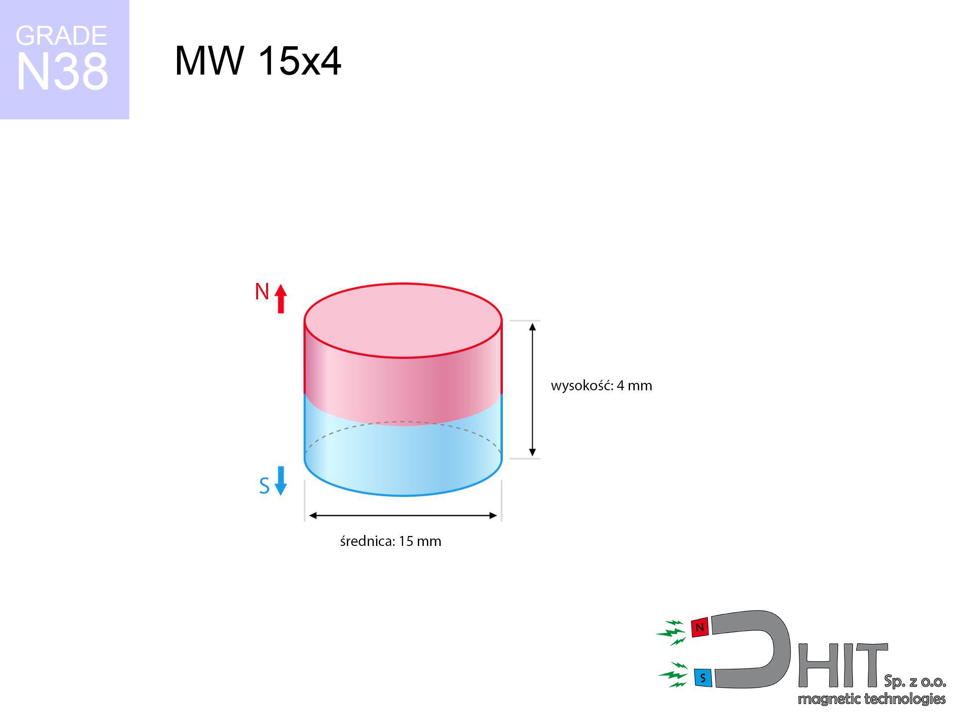
MW 15x4 / N38 - cylindrical magnet
cylindrical magnet
Catalog no 010030
GTIN/EAN: 5906301810292
Diameter Ø
15 mm [±0,1 mm]
Height
4 mm [±0,1 mm]
Weight
5.3 g
Magnetization Direction
↑ axial
Load capacity
4.22 kg / 41.38 N
Magnetic Induction
291.60 mT / 2916 Gs
Coating
[NiCuNi] Nickel
1.968 ZŁ with VAT / pcs + price for transport
1.600 ZŁ net + 23% VAT / pcs
bulk discounts:
Need more?
Contact us by phone
+48 888 99 98 98
otherwise contact us through
our online form
the contact section.
Weight along with appearance of magnetic components can be calculated with our
magnetic mass calculator.
Orders placed before 14:00 will be shipped the same business day.
Physical properties - MW 15x4 / N38 - cylindrical magnet
Specification / characteristics - MW 15x4 / N38 - cylindrical magnet
| properties | values |
|---|---|
| Cat. no. | 010030 |
| GTIN/EAN | 5906301810292 |
| Production/Distribution | Dhit sp. z o.o. |
| Country of origin | Poland / China / Germany |
| Customs code | 85059029 |
| Diameter Ø | 15 mm [±0,1 mm] |
| Height | 4 mm [±0,1 mm] |
| Weight | 5.3 g |
| Magnetization Direction | ↑ axial |
| Load capacity ~ ? | 4.22 kg / 41.38 N |
| Magnetic Induction ~ ? | 291.60 mT / 2916 Gs |
| Coating | [NiCuNi] Nickel |
| Manufacturing Tolerance | ±0.1 mm |
Magnetic properties of material N38
| properties | values | units |
|---|---|---|
| remenance Br [min. - max.] ? | 12.2-12.6 | kGs |
| remenance Br [min. - max.] ? | 1220-1260 | mT |
| coercivity bHc ? | 10.8-11.5 | kOe |
| coercivity bHc ? | 860-915 | kA/m |
| actual internal force iHc | ≥ 12 | kOe |
| actual internal force iHc | ≥ 955 | kA/m |
| energy density [min. - max.] ? | 36-38 | BH max MGOe |
| energy density [min. - max.] ? | 287-303 | BH max KJ/m |
| max. temperature ? | ≤ 80 | °C |
Physical properties of sintered neodymium magnets Nd2Fe14B at 20°C
| properties | values | units |
|---|---|---|
| Vickers hardness | ≥550 | Hv |
| Density | ≥7.4 | g/cm3 |
| Curie Temperature TC | 312 - 380 | °C |
| Curie Temperature TF | 593 - 716 | °F |
| Specific resistance | 150 | μΩ⋅cm |
| Bending strength | 250 | MPa |
| Compressive strength | 1000~1100 | MPa |
| Thermal expansion parallel (∥) to orientation (M) | (3-4) x 10-6 | °C-1 |
| Thermal expansion perpendicular (⊥) to orientation (M) | -(1-3) x 10-6 | °C-1 |
| Young's modulus | 1.7 x 10⁴ | kg/mm² |
Technical simulation of the product - technical parameters
Presented values represent the direct effect of a engineering calculation. Results rely on algorithms for the material Nd2Fe14B. Actual conditions might slightly deviate from the simulation results. Use these calculations as a supplementary guide during assembly planning.
Table 1: Static pull force (force vs distance) - interaction chart
MW 15x4 / N38
| Distance (mm) | Induction (Gauss) / mT | Pull Force (kg/lbs/g/N) | Risk Status |
|---|---|---|---|
| 0 mm |
2915 Gs
291.5 mT
|
4.22 kg / 9.30 lbs
4220.0 g / 41.4 N
|
warning |
| 1 mm |
2620 Gs
262.0 mT
|
3.41 kg / 7.51 lbs
3408.2 g / 33.4 N
|
warning |
| 2 mm |
2276 Gs
227.6 mT
|
2.57 kg / 5.67 lbs
2571.6 g / 25.2 N
|
warning |
| 3 mm |
1928 Gs
192.8 mT
|
1.85 kg / 4.07 lbs
1845.5 g / 18.1 N
|
weak grip |
| 5 mm |
1324 Gs
132.4 mT
|
0.87 kg / 1.92 lbs
870.3 g / 8.5 N
|
weak grip |
| 10 mm |
505 Gs
50.5 mT
|
0.13 kg / 0.28 lbs
126.7 g / 1.2 N
|
weak grip |
| 15 mm |
222 Gs
22.2 mT
|
0.02 kg / 0.05 lbs
24.4 g / 0.2 N
|
weak grip |
| 20 mm |
113 Gs
11.3 mT
|
0.01 kg / 0.01 lbs
6.3 g / 0.1 N
|
weak grip |
| 30 mm |
40 Gs
4.0 mT
|
0.00 kg / 0.00 lbs
0.8 g / 0.0 N
|
weak grip |
| 50 mm |
10 Gs
1.0 mT
|
0.00 kg / 0.00 lbs
0.0 g / 0.0 N
|
weak grip |
Table 2: Shear load (vertical surface)
MW 15x4 / N38
| Distance (mm) | Friction coefficient | Pull Force (kg/lbs/g/N) |
|---|---|---|
| 0 mm | Stal (~0.2) |
0.84 kg / 1.86 lbs
844.0 g / 8.3 N
|
| 1 mm | Stal (~0.2) |
0.68 kg / 1.50 lbs
682.0 g / 6.7 N
|
| 2 mm | Stal (~0.2) |
0.51 kg / 1.13 lbs
514.0 g / 5.0 N
|
| 3 mm | Stal (~0.2) |
0.37 kg / 0.82 lbs
370.0 g / 3.6 N
|
| 5 mm | Stal (~0.2) |
0.17 kg / 0.38 lbs
174.0 g / 1.7 N
|
| 10 mm | Stal (~0.2) |
0.03 kg / 0.06 lbs
26.0 g / 0.3 N
|
| 15 mm | Stal (~0.2) |
0.00 kg / 0.01 lbs
4.0 g / 0.0 N
|
| 20 mm | Stal (~0.2) |
0.00 kg / 0.00 lbs
2.0 g / 0.0 N
|
| 30 mm | Stal (~0.2) |
0.00 kg / 0.00 lbs
0.0 g / 0.0 N
|
| 50 mm | Stal (~0.2) |
0.00 kg / 0.00 lbs
0.0 g / 0.0 N
|
Table 3: Wall mounting (sliding) - vertical pull
MW 15x4 / N38
| Surface type | Friction coefficient / % Mocy | Max load (kg/lbs/g/N) |
|---|---|---|
| Raw steel |
µ = 0.3
30% Nominalnej Siły
|
1.27 kg / 2.79 lbs
1266.0 g / 12.4 N
|
| Painted steel (standard) |
µ = 0.2
20% Nominalnej Siły
|
0.84 kg / 1.86 lbs
844.0 g / 8.3 N
|
| Oily/slippery steel |
µ = 0.1
10% Nominalnej Siły
|
0.42 kg / 0.93 lbs
422.0 g / 4.1 N
|
| Magnet with anti-slip rubber |
µ = 0.5
50% Nominalnej Siły
|
2.11 kg / 4.65 lbs
2110.0 g / 20.7 N
|
Table 4: Steel thickness (substrate influence) - sheet metal selection
MW 15x4 / N38
| Steel thickness (mm) | % power | Real pull force (kg/lbs/g/N) |
|---|---|---|
| 0.5 mm |
|
0.42 kg / 0.93 lbs
422.0 g / 4.1 N
|
| 1 mm |
|
1.06 kg / 2.33 lbs
1055.0 g / 10.3 N
|
| 2 mm |
|
2.11 kg / 4.65 lbs
2110.0 g / 20.7 N
|
| 3 mm |
|
3.17 kg / 6.98 lbs
3165.0 g / 31.0 N
|
| 5 mm |
|
4.22 kg / 9.30 lbs
4220.0 g / 41.4 N
|
| 10 mm |
|
4.22 kg / 9.30 lbs
4220.0 g / 41.4 N
|
| 11 mm |
|
4.22 kg / 9.30 lbs
4220.0 g / 41.4 N
|
| 12 mm |
|
4.22 kg / 9.30 lbs
4220.0 g / 41.4 N
|
Table 5: Thermal stability (material behavior) - thermal limit
MW 15x4 / N38
| Ambient temp. (°C) | Power loss | Remaining pull (kg/lbs/g/N) | Status |
|---|---|---|---|
| 20 °C | 0.0% |
4.22 kg / 9.30 lbs
4220.0 g / 41.4 N
|
OK |
| 40 °C | -2.2% |
4.13 kg / 9.10 lbs
4127.2 g / 40.5 N
|
OK |
| 60 °C | -4.4% |
4.03 kg / 8.89 lbs
4034.3 g / 39.6 N
|
|
| 80 °C | -6.6% |
3.94 kg / 8.69 lbs
3941.5 g / 38.7 N
|
|
| 100 °C | -28.8% |
3.00 kg / 6.62 lbs
3004.6 g / 29.5 N
|
Table 6: Two magnets (repulsion) - field collision
MW 15x4 / N38
| Gap (mm) | Attraction (kg/lbs) (N-S) | Lateral Force (kg/lbs/g/N) | Repulsion (kg/lbs) (N-N) |
|---|---|---|---|
| 0 mm |
9.26 kg / 20.41 lbs
4 518 Gs
|
1.39 kg / 3.06 lbs
1389 g / 13.6 N
|
N/A |
| 1 mm |
8.40 kg / 18.53 lbs
5 555 Gs
|
1.26 kg / 2.78 lbs
1261 g / 12.4 N
|
7.56 kg / 16.68 lbs
~0 Gs
|
| 2 mm |
7.48 kg / 16.48 lbs
5 239 Gs
|
1.12 kg / 2.47 lbs
1122 g / 11.0 N
|
6.73 kg / 14.84 lbs
~0 Gs
|
| 3 mm |
6.54 kg / 14.42 lbs
4 901 Gs
|
0.98 kg / 2.16 lbs
981 g / 9.6 N
|
5.89 kg / 12.98 lbs
~0 Gs
|
| 5 mm |
4.80 kg / 10.59 lbs
4 200 Gs
|
0.72 kg / 1.59 lbs
721 g / 7.1 N
|
4.32 kg / 9.53 lbs
~0 Gs
|
| 10 mm |
1.91 kg / 4.21 lbs
2 648 Gs
|
0.29 kg / 0.63 lbs
286 g / 2.8 N
|
1.72 kg / 3.79 lbs
~0 Gs
|
| 20 mm |
0.28 kg / 0.61 lbs
1 010 Gs
|
0.04 kg / 0.09 lbs
42 g / 0.4 N
|
0.25 kg / 0.55 lbs
~0 Gs
|
| 50 mm |
0.00 kg / 0.01 lbs
128 Gs
|
0.00 kg / 0.00 lbs
1 g / 0.0 N
|
0.00 kg / 0.00 lbs
~0 Gs
|
| 60 mm |
0.00 kg / 0.00 lbs
79 Gs
|
0.00 kg / 0.00 lbs
0 g / 0.0 N
|
0.00 kg / 0.00 lbs
~0 Gs
|
| 70 mm |
0.00 kg / 0.00 lbs
52 Gs
|
0.00 kg / 0.00 lbs
0 g / 0.0 N
|
0.00 kg / 0.00 lbs
~0 Gs
|
| 80 mm |
0.00 kg / 0.00 lbs
36 Gs
|
0.00 kg / 0.00 lbs
0 g / 0.0 N
|
0.00 kg / 0.00 lbs
~0 Gs
|
| 90 mm |
0.00 kg / 0.00 lbs
26 Gs
|
0.00 kg / 0.00 lbs
0 g / 0.0 N
|
0.00 kg / 0.00 lbs
~0 Gs
|
| 100 mm |
0.00 kg / 0.00 lbs
19 Gs
|
0.00 kg / 0.00 lbs
0 g / 0.0 N
|
0.00 kg / 0.00 lbs
~0 Gs
|
Table 7: Protective zones (implants) - warnings
MW 15x4 / N38
| Object / Device | Limit (Gauss) / mT | Safe distance |
|---|---|---|
| Pacemaker | 5 Gs (0.5 mT) | 6.5 cm |
| Hearing aid | 10 Gs (1.0 mT) | 5.0 cm |
| Timepiece | 20 Gs (2.0 mT) | 4.0 cm |
| Phone / Smartphone | 40 Gs (4.0 mT) | 3.0 cm |
| Remote | 50 Gs (5.0 mT) | 3.0 cm |
| Payment card | 400 Gs (40.0 mT) | 1.5 cm |
| HDD hard drive | 600 Gs (60.0 mT) | 1.0 cm |
Table 8: Collisions (kinetic energy) - warning
MW 15x4 / N38
| Start from (mm) | Speed (km/h) | Energy (J) | Predicted outcome |
|---|---|---|---|
| 10 mm |
28.99 km/h
(8.05 m/s)
|
0.17 J | |
| 30 mm |
49.30 km/h
(13.69 m/s)
|
0.50 J | |
| 50 mm |
63.63 km/h
(17.68 m/s)
|
0.83 J | |
| 100 mm |
89.99 km/h
(25.00 m/s)
|
1.66 J |
Table 9: Anti-corrosion coating durability
MW 15x4 / N38
| Technical parameter | Value / Description |
|---|---|
| Coating type | [NiCuNi] Nickel |
| Layer structure | Nickel - Copper - Nickel |
| Layer thickness | 10-20 µm |
| Salt spray test (SST) ? | 24 h |
| Recommended environment | Indoors only (dry) |
Table 10: Electrical data (Flux)
MW 15x4 / N38
| Parameter | Value | SI Unit / Description |
|---|---|---|
| Magnetic Flux | 5 659 Mx | 56.6 µWb |
| Pc Coefficient | 0.37 | Low (Flat) |
Table 11: Hydrostatics and buoyancy
MW 15x4 / N38
| Environment | Effective steel pull | Effect |
|---|---|---|
| Air (land) | 4.22 kg | Standard |
| Water (riverbed) |
4.83 kg
(+0.61 kg buoyancy gain)
|
+14.5% |
1. Sliding resistance
*Warning: On a vertical wall, the magnet retains merely ~20% of its perpendicular strength.
2. Efficiency vs thickness
*Thin steel (e.g. computer case) severely limits the holding force.
3. Power loss vs temp
*For standard magnets, the critical limit is 80°C.
4. Demagnetization curve and operating point (B-H)
chart generated for the permeance coefficient Pc (Permeance Coefficient) = 0.37
This simulation demonstrates the magnetic stability of the selected magnet under specific geometric conditions. The solid red line represents the demagnetization curve (material potential), while the dashed blue line is the load line based on the magnet's geometry. The Pc (Permeance Coefficient), also known as the load line slope, is a dimensionless value that describes the relationship between the magnet's shape and its magnetic stability. The intersection of these two lines (the black dot) is the operating point — it determines the actual magnetic flux density generated by the magnet in this specific configuration. A higher Pc value means the magnet is more 'slender' (tall relative to its area), resulting in a higher operating point and better resistance to irreversible demagnetization caused by external fields or temperature. A value of 0.42 is relatively low (typical for flat magnets), meaning the operating point is closer to the 'knee' of the curve — caution is advised when operating at temperatures near the maximum limit to avoid strength loss.
Elemental analysis
| iron (Fe) | 64% – 68% |
| neodymium (Nd) | 29% – 32% |
| boron (B) | 1.1% – 1.2% |
| dysprosium (Dy) | 0.5% – 2.0% |
| coating (Ni-Cu-Ni) | < 0.05% |
Environmental data
| recyclability (EoL) | 100% |
| recycled raw materials | ~10% (pre-cons) |
| carbon footprint | low / zredukowany |
| waste code (EWC) | 16 02 16 |
Check out also deals


![UMGW 36x18x8 [M8] GW / N38 - magnetic holder internal thread](https://cdn3.dhit.pl/graphics/products/um-36x18x8-m8-gw-foj.jpg "UMGW 36x18x8 [M8] GW / N38 - magnetic holder internal thread")
Strengths and weaknesses of neodymium magnets.
Strengths
- They have stable power, and over around 10 years their attraction force decreases symbolically – ~1% (according to theory),
- They have excellent resistance to weakening of magnetic properties due to external magnetic sources,
- In other words, due to the reflective surface of nickel, the element becomes visually attractive,
- They are known for high magnetic induction at the operating surface, making them more effective,
- Through (appropriate) combination of ingredients, they can achieve high thermal strength, enabling functioning at temperatures reaching 230°C and above...
- Thanks to modularity in forming and the ability to customize to client solutions,
- Universal use in innovative solutions – they are commonly used in magnetic memories, electromotive mechanisms, advanced medical instruments, also industrial machines.
- Thanks to their power density, small magnets offer high operating force, with minimal size,
Disadvantages
- Brittleness is one of their disadvantages. Upon strong impact they can fracture. We recommend keeping them in a special holder, which not only secures them against impacts but also raises their durability
- We warn that neodymium magnets can lose their power at high temperatures. To prevent this, we advise our specialized [AH] magnets, which work effectively even at 230°C.
- Magnets exposed to a humid environment can rust. Therefore during using outdoors, we advise using waterproof magnets made of rubber, plastic or other material resistant to moisture
- We recommend a housing - magnetic mechanism, due to difficulties in creating nuts inside the magnet and complicated forms.
- Health risk related to microscopic parts of magnets are risky, in case of ingestion, which gains importance in the aspect of protecting the youngest. Additionally, tiny parts of these products are able to be problematic in diagnostics medical when they are in the body.
- High unit price – neodymium magnets are more expensive than other types of magnets (e.g. ferrite), which hinders application in large quantities
Pull force analysis
Maximum lifting capacity of the magnet – what affects it?
- using a sheet made of mild steel, acting as a magnetic yoke
- with a thickness of at least 10 mm
- with a surface perfectly flat
- without any insulating layer between the magnet and steel
- under vertical force vector (90-degree angle)
- in neutral thermal conditions
Determinants of lifting force in real conditions
- Clearance – the presence of foreign body (paint, tape, gap) acts as an insulator, which lowers capacity steeply (even by 50% at 0.5 mm).
- Loading method – declared lifting capacity refers to pulling vertically. When slipping, the magnet holds significantly lower power (often approx. 20-30% of nominal force).
- Wall thickness – thin material does not allow full use of the magnet. Magnetic flux passes through the material instead of generating force.
- Metal type – not every steel reacts the same. High carbon content weaken the interaction with the magnet.
- Plate texture – ground elements ensure maximum contact, which increases field saturation. Rough surfaces reduce efficiency.
- Temperature – temperature increase results in weakening of induction. It is worth remembering the thermal limit for a given model.
Lifting capacity was determined using a smooth steel plate of optimal thickness (min. 20 mm), under perpendicular detachment force, whereas under parallel forces the holding force is lower. Additionally, even a minimal clearance between the magnet’s surface and the plate reduces the load capacity.
Safe handling of neodymium magnets
Allergy Warning
Some people suffer from a contact allergy to Ni, which is the common plating for NdFeB magnets. Extended handling might lead to an allergic reaction. We suggest use safety gloves.
Medical interference
For implant holders: Powerful magnets disrupt medical devices. Keep at least 30 cm distance or ask another person to work with the magnets.
Beware of splinters
Beware of splinters. Magnets can explode upon violent connection, launching shards into the air. We recommend safety glasses.
Crushing force
Danger of trauma: The pulling power is so great that it can result in blood blisters, crushing, and broken bones. Use thick gloves.
Powerful field
Use magnets with awareness. Their huge power can shock even professionals. Plan your moves and do not underestimate their force.
Demagnetization risk
Standard neodymium magnets (N-type) lose power when the temperature surpasses 80°C. The loss of strength is permanent.
This is not a toy
Product intended for adults. Tiny parts pose a choking risk, leading to serious injuries. Store away from children and animals.
Machining danger
Combustion risk: Neodymium dust is explosive. Do not process magnets without safety gear as this risks ignition.
Keep away from electronics
A strong magnetic field disrupts the operation of compasses in phones and GPS navigation. Keep magnets near a smartphone to avoid breaking the sensors.
Keep away from computers
Equipment safety: Strong magnets can damage payment cards and sensitive devices (heart implants, hearing aids, timepieces).
Tabela kosztu i czasu dostawy
Płatność przed wysyłką:

GLS kurier
Przesyłka będzie u Ciebie za 2-3 dni
14.99 ZŁ

InPost Paczkomaty 24/7
Przesyłka będzie u Ciebie za 1-2 dni
12.30 ZŁ
Płatność przy odbiorze (pobranie):
GLS kurier
Przesyłka będzie u Ciebie za 1-2 dni
23.00 ZŁ
Rate the product
Your rating