

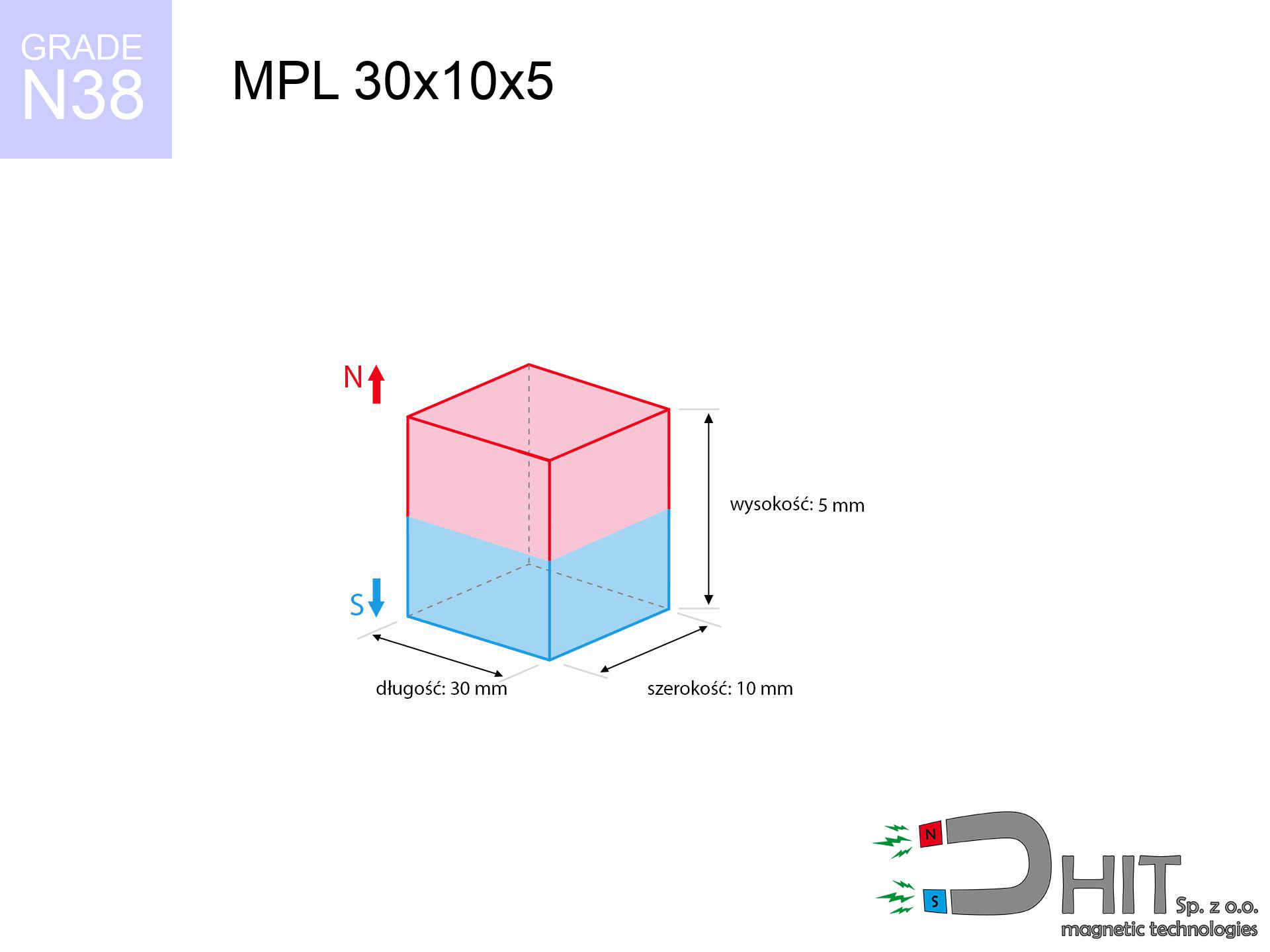
MPL 30x10x5 / N38 - lamellar magnet
lamellar magnet
Catalog no 020138
GTIN/EAN: 5906301811442
length
30 mm [±0,1 mm]
Width
10 mm [±0,1 mm]
Height
5 mm [±0,1 mm]
Weight
11.25 g
Magnetization Direction
↑ axial
Load capacity
8.89 kg / 87.23 N
Magnetic Induction
329.52 mT / 3295 Gs
Coating
[NiCuNi] Nickel
4.26 ZŁ with VAT / pcs + price for transport
3.46 ZŁ net + 23% VAT / pcs
bulk discounts:
Need more?
Call us now
+48 888 99 98 98
otherwise send us a note using
contact form
the contact section.
Force along with appearance of neodymium magnets can be estimated using our
online calculation tool.
Same-day processing for orders placed before 14:00.
Technical specification - MPL 30x10x5 / N38 - lamellar magnet
Specification / characteristics - MPL 30x10x5 / N38 - lamellar magnet
| properties | values |
|---|---|
| Cat. no. | 020138 |
| GTIN/EAN | 5906301811442 |
| Production/Distribution | Dhit sp. z o.o. |
| Country of origin | Poland / China / Germany |
| Customs code | 85059029 |
| length | 30 mm [±0,1 mm] |
| Width | 10 mm [±0,1 mm] |
| Height | 5 mm [±0,1 mm] |
| Weight | 11.25 g |
| Magnetization Direction | ↑ axial |
| Load capacity ~ ? | 8.89 kg / 87.23 N |
| Magnetic Induction ~ ? | 329.52 mT / 3295 Gs |
| Coating | [NiCuNi] Nickel |
| Manufacturing Tolerance | ±0.1 mm |
Magnetic properties of material N38
| properties | values | units |
|---|---|---|
| remenance Br [min. - max.] ? | 12.2-12.6 | kGs |
| remenance Br [min. - max.] ? | 1220-1260 | mT |
| coercivity bHc ? | 10.8-11.5 | kOe |
| coercivity bHc ? | 860-915 | kA/m |
| actual internal force iHc | ≥ 12 | kOe |
| actual internal force iHc | ≥ 955 | kA/m |
| energy density [min. - max.] ? | 36-38 | BH max MGOe |
| energy density [min. - max.] ? | 287-303 | BH max KJ/m |
| max. temperature ? | ≤ 80 | °C |
Physical properties of sintered neodymium magnets Nd2Fe14B at 20°C
| properties | values | units |
|---|---|---|
| Vickers hardness | ≥550 | Hv |
| Density | ≥7.4 | g/cm3 |
| Curie Temperature TC | 312 - 380 | °C |
| Curie Temperature TF | 593 - 716 | °F |
| Specific resistance | 150 | μΩ⋅cm |
| Bending strength | 250 | MPa |
| Compressive strength | 1000~1100 | MPa |
| Thermal expansion parallel (∥) to orientation (M) | (3-4) x 10-6 | °C-1 |
| Thermal expansion perpendicular (⊥) to orientation (M) | -(1-3) x 10-6 | °C-1 |
| Young's modulus | 1.7 x 10⁴ | kg/mm² |
Physical analysis of the magnet - technical parameters
Presented values represent the result of a mathematical analysis. Values rely on algorithms for the class Nd2Fe14B. Real-world conditions may differ. Please consider these calculations as a reference point during assembly planning.
Table 1: Static force (pull vs distance) - characteristics
MPL 30x10x5 / N38
| Distance (mm) | Induction (Gauss) / mT | Pull Force (kg/lbs/g/N) | Risk Status |
|---|---|---|---|
| 0 mm |
3294 Gs
329.4 mT
|
8.89 kg / 19.60 LBS
8890.0 g / 87.2 N
|
warning |
| 1 mm |
2866 Gs
286.6 mT
|
6.73 kg / 14.84 LBS
6731.1 g / 66.0 N
|
warning |
| 2 mm |
2424 Gs
242.4 mT
|
4.82 kg / 10.62 LBS
4816.4 g / 47.2 N
|
warning |
| 3 mm |
2022 Gs
202.2 mT
|
3.35 kg / 7.38 LBS
3349.6 g / 32.9 N
|
warning |
| 5 mm |
1397 Gs
139.7 mT
|
1.60 kg / 3.53 LBS
1600.3 g / 15.7 N
|
safe |
| 10 mm |
615 Gs
61.5 mT
|
0.31 kg / 0.68 LBS
309.8 g / 3.0 N
|
safe |
| 15 mm |
314 Gs
31.4 mT
|
0.08 kg / 0.18 LBS
80.6 g / 0.8 N
|
safe |
| 20 mm |
177 Gs
17.7 mT
|
0.03 kg / 0.06 LBS
25.8 g / 0.3 N
|
safe |
| 30 mm |
70 Gs
7.0 mT
|
0.00 kg / 0.01 LBS
4.1 g / 0.0 N
|
safe |
| 50 mm |
19 Gs
1.9 mT
|
0.00 kg / 0.00 LBS
0.3 g / 0.0 N
|
safe |
Table 2: Shear force (wall)
MPL 30x10x5 / N38
| Distance (mm) | Friction coefficient | Pull Force (kg/lbs/g/N) |
|---|---|---|
| 0 mm | Stal (~0.2) |
1.78 kg / 3.92 LBS
1778.0 g / 17.4 N
|
| 1 mm | Stal (~0.2) |
1.35 kg / 2.97 LBS
1346.0 g / 13.2 N
|
| 2 mm | Stal (~0.2) |
0.96 kg / 2.13 LBS
964.0 g / 9.5 N
|
| 3 mm | Stal (~0.2) |
0.67 kg / 1.48 LBS
670.0 g / 6.6 N
|
| 5 mm | Stal (~0.2) |
0.32 kg / 0.71 LBS
320.0 g / 3.1 N
|
| 10 mm | Stal (~0.2) |
0.06 kg / 0.14 LBS
62.0 g / 0.6 N
|
| 15 mm | Stal (~0.2) |
0.02 kg / 0.04 LBS
16.0 g / 0.2 N
|
| 20 mm | Stal (~0.2) |
0.01 kg / 0.01 LBS
6.0 g / 0.1 N
|
| 30 mm | Stal (~0.2) |
0.00 kg / 0.00 LBS
0.0 g / 0.0 N
|
| 50 mm | Stal (~0.2) |
0.00 kg / 0.00 LBS
0.0 g / 0.0 N
|
Table 3: Vertical assembly (shearing) - behavior on slippery surfaces
MPL 30x10x5 / N38
| Surface type | Friction coefficient / % Mocy | Max load (kg/lbs/g/N) |
|---|---|---|
| Raw steel |
µ = 0.3
30% Nominalnej Siły
|
2.67 kg / 5.88 LBS
2667.0 g / 26.2 N
|
| Painted steel (standard) |
µ = 0.2
20% Nominalnej Siły
|
1.78 kg / 3.92 LBS
1778.0 g / 17.4 N
|
| Oily/slippery steel |
µ = 0.1
10% Nominalnej Siły
|
0.89 kg / 1.96 LBS
889.0 g / 8.7 N
|
| Magnet with anti-slip rubber |
µ = 0.5
50% Nominalnej Siły
|
4.45 kg / 9.80 LBS
4445.0 g / 43.6 N
|
Table 4: Material efficiency (substrate influence) - power losses
MPL 30x10x5 / N38
| Steel thickness (mm) | % power | Real pull force (kg/lbs/g/N) |
|---|---|---|
| 0.5 mm |
|
0.89 kg / 1.96 LBS
889.0 g / 8.7 N
|
| 1 mm |
|
2.22 kg / 4.90 LBS
2222.5 g / 21.8 N
|
| 2 mm |
|
4.45 kg / 9.80 LBS
4445.0 g / 43.6 N
|
| 3 mm |
|
6.67 kg / 14.70 LBS
6667.5 g / 65.4 N
|
| 5 mm |
|
8.89 kg / 19.60 LBS
8890.0 g / 87.2 N
|
| 10 mm |
|
8.89 kg / 19.60 LBS
8890.0 g / 87.2 N
|
| 11 mm |
|
8.89 kg / 19.60 LBS
8890.0 g / 87.2 N
|
| 12 mm |
|
8.89 kg / 19.60 LBS
8890.0 g / 87.2 N
|
Table 5: Thermal stability (stability) - power drop
MPL 30x10x5 / N38
| Ambient temp. (°C) | Power loss | Remaining pull (kg/lbs/g/N) | Status |
|---|---|---|---|
| 20 °C | 0.0% |
8.89 kg / 19.60 LBS
8890.0 g / 87.2 N
|
OK |
| 40 °C | -2.2% |
8.69 kg / 19.17 LBS
8694.4 g / 85.3 N
|
OK |
| 60 °C | -4.4% |
8.50 kg / 18.74 LBS
8498.8 g / 83.4 N
|
|
| 80 °C | -6.6% |
8.30 kg / 18.31 LBS
8303.3 g / 81.5 N
|
|
| 100 °C | -28.8% |
6.33 kg / 13.95 LBS
6329.7 g / 62.1 N
|
Table 6: Two magnets (repulsion) - field collision
MPL 30x10x5 / N38
| Gap (mm) | Attraction (kg/lbs) (N-S) | Shear Strength (kg/lbs/g/N) | Repulsion (kg/lbs) (N-N) |
|---|---|---|---|
| 0 mm |
20.06 kg / 44.23 LBS
4 689 Gs
|
3.01 kg / 6.63 LBS
3010 g / 29.5 N
|
N/A |
| 1 mm |
17.63 kg / 38.86 LBS
6 174 Gs
|
2.64 kg / 5.83 LBS
2644 g / 25.9 N
|
15.86 kg / 34.98 LBS
~0 Gs
|
| 2 mm |
15.19 kg / 33.49 LBS
5 732 Gs
|
2.28 kg / 5.02 LBS
2279 g / 22.4 N
|
13.67 kg / 30.14 LBS
~0 Gs
|
| 3 mm |
12.92 kg / 28.47 LBS
5 285 Gs
|
1.94 kg / 4.27 LBS
1937 g / 19.0 N
|
11.62 kg / 25.63 LBS
~0 Gs
|
| 5 mm |
9.08 kg / 20.03 LBS
4 432 Gs
|
1.36 kg / 3.00 LBS
1363 g / 13.4 N
|
8.18 kg / 18.02 LBS
~0 Gs
|
| 10 mm |
3.61 kg / 7.96 LBS
2 795 Gs
|
0.54 kg / 1.19 LBS
542 g / 5.3 N
|
3.25 kg / 7.17 LBS
~0 Gs
|
| 20 mm |
0.70 kg / 1.54 LBS
1 230 Gs
|
0.10 kg / 0.23 LBS
105 g / 1.0 N
|
0.63 kg / 1.39 LBS
~0 Gs
|
| 50 mm |
0.02 kg / 0.05 LBS
217 Gs
|
0.00 kg / 0.01 LBS
3 g / 0.0 N
|
0.02 kg / 0.04 LBS
~0 Gs
|
| 60 mm |
0.01 kg / 0.02 LBS
141 Gs
|
0.00 kg / 0.00 LBS
1 g / 0.0 N
|
0.00 kg / 0.00 LBS
~0 Gs
|
| 70 mm |
0.00 kg / 0.01 LBS
96 Gs
|
0.00 kg / 0.00 LBS
1 g / 0.0 N
|
0.00 kg / 0.00 LBS
~0 Gs
|
| 80 mm |
0.00 kg / 0.00 LBS
68 Gs
|
0.00 kg / 0.00 LBS
0 g / 0.0 N
|
0.00 kg / 0.00 LBS
~0 Gs
|
| 90 mm |
0.00 kg / 0.00 LBS
50 Gs
|
0.00 kg / 0.00 LBS
0 g / 0.0 N
|
0.00 kg / 0.00 LBS
~0 Gs
|
| 100 mm |
0.00 kg / 0.00 LBS
38 Gs
|
0.00 kg / 0.00 LBS
0 g / 0.0 N
|
0.00 kg / 0.00 LBS
~0 Gs
|
Table 7: Safety (HSE) (electronics) - warnings
MPL 30x10x5 / N38
| Object / Device | Limit (Gauss) / mT | Safe distance |
|---|---|---|
| Pacemaker | 5 Gs (0.5 mT) | 8.5 cm |
| Hearing aid | 10 Gs (1.0 mT) | 6.5 cm |
| Mechanical watch | 20 Gs (2.0 mT) | 5.0 cm |
| Phone / Smartphone | 40 Gs (4.0 mT) | 4.0 cm |
| Remote | 50 Gs (5.0 mT) | 3.5 cm |
| Payment card | 400 Gs (40.0 mT) | 1.5 cm |
| HDD hard drive | 600 Gs (60.0 mT) | 1.5 cm |
Table 8: Impact energy (cracking risk) - warning
MPL 30x10x5 / N38
| Start from (mm) | Speed (km/h) | Energy (J) | Predicted outcome |
|---|---|---|---|
| 10 mm |
28.96 km/h
(8.04 m/s)
|
0.36 J | |
| 30 mm |
49.12 km/h
(13.64 m/s)
|
1.05 J | |
| 50 mm |
63.39 km/h
(17.61 m/s)
|
1.74 J | |
| 100 mm |
89.65 km/h
(24.90 m/s)
|
3.49 J |
Table 9: Surface protection spec
MPL 30x10x5 / N38
| Technical parameter | Value / Description |
|---|---|
| Coating type | [NiCuNi] Nickel |
| Layer structure | Nickel - Copper - Nickel |
| Layer thickness | 10-20 µm |
| Salt spray test (SST) ? | 24 h |
| Recommended environment | Indoors only (dry) |
Table 10: Electrical data (Flux)
MPL 30x10x5 / N38
| Parameter | Value | SI Unit / Description |
|---|---|---|
| Magnetic Flux | 9 370 Mx | 93.7 µWb |
| Pc Coefficient | 0.35 | Low (Flat) |
Table 11: Underwater work (magnet fishing)
MPL 30x10x5 / N38
| Environment | Effective steel pull | Effect |
|---|---|---|
| Air (land) | 8.89 kg | Standard |
| Water (riverbed) |
10.18 kg
(+1.29 kg buoyancy gain)
|
+14.5% |
1. Wall mount (shear)
*Note: On a vertical wall, the magnet holds only ~20% of its perpendicular strength.
2. Steel thickness impact
*Thin metal sheet (e.g. computer case) significantly weakens the holding force.
3. Thermal stability
*For standard magnets, the max working temp is 80°C.
4. Demagnetization curve and operating point (B-H)
chart generated for the permeance coefficient Pc (Permeance Coefficient) = 0.35
This simulation demonstrates the magnetic stability of the selected magnet under specific geometric conditions. The solid red line represents the demagnetization curve (material potential), while the dashed blue line is the load line based on the magnet's geometry. The Pc (Permeance Coefficient), also known as the load line slope, is a dimensionless value that describes the relationship between the magnet's shape and its magnetic stability. The intersection of these two lines (the black dot) is the operating point — it determines the actual magnetic flux density generated by the magnet in this specific configuration. A higher Pc value means the magnet is more 'slender' (tall relative to its area), resulting in a higher operating point and better resistance to irreversible demagnetization caused by external fields or temperature. A value of 0.42 is relatively low (typical for flat magnets), meaning the operating point is closer to the 'knee' of the curve — caution is advised when operating at temperatures near the maximum limit to avoid strength loss.
Material specification
| iron (Fe) | 64% – 68% |
| neodymium (Nd) | 29% – 32% |
| boron (B) | 1.1% – 1.2% |
| dysprosium (Dy) | 0.5% – 2.0% |
| coating (Ni-Cu-Ni) | < 0.05% |
Ecology and recycling (GPSR)
| recyclability (EoL) | 100% |
| recycled raw materials | ~10% (pre-cons) |
| carbon footprint | low / zredukowany |
| waste code (EWC) | 16 02 16 |
View also proposals


Strengths as well as weaknesses of Nd2Fe14B magnets.
Benefits
- They retain magnetic properties for nearly ten years – the drop is just ~1% (based on simulations),
- Neodymium magnets are characterized by extremely resistant to magnetic field loss caused by external interference,
- A magnet with a shiny nickel surface is more attractive,
- Magnetic induction on the top side of the magnet is extremely intense,
- Thanks to resistance to high temperature, they can operate (depending on the shape) even at temperatures up to 230°C and higher...
- In view of the ability of accurate forming and adaptation to specialized solutions, neodymium magnets can be manufactured in a broad palette of shapes and sizes, which expands the range of possible applications,
- Versatile presence in advanced technology sectors – they are commonly used in computer drives, motor assemblies, medical devices, and modern systems.
- Compactness – despite small sizes they generate large force, making them ideal for precision applications
Disadvantages
- They are fragile upon heavy impacts. To avoid cracks, it is worth securing magnets in a protective case. Such protection not only protects the magnet but also increases its resistance to damage
- Neodymium magnets lose force when exposed to high temperatures. After reaching 80°C, many of them experience permanent weakening of power (a factor is the shape as well as dimensions of the magnet). We offer magnets specially adapted to work at temperatures up to 230°C marked [AH], which are very resistant to heat
- When exposed to humidity, magnets usually rust. To use them in conditions outside, it is recommended to use protective magnets, such as magnets in rubber or plastics, which prevent oxidation as well as corrosion.
- Due to limitations in realizing nuts and complex forms in magnets, we propose using a housing - magnetic holder.
- Possible danger resulting from small fragments of magnets pose a threat, in case of ingestion, which gains importance in the context of child safety. Additionally, tiny parts of these products can complicate diagnosis medical in case of swallowing.
- Higher cost of purchase is a significant factor to consider compared to ceramic magnets, especially in budget applications
Pull force analysis
Best holding force of the magnet in ideal parameters – what affects it?
- with the use of a yoke made of special test steel, ensuring full magnetic saturation
- possessing a massiveness of minimum 10 mm to ensure full flux closure
- characterized by even structure
- without any air gap between the magnet and steel
- under vertical force vector (90-degree angle)
- at room temperature
Determinants of lifting force in real conditions
- Distance – existence of foreign body (paint, tape, air) interrupts the magnetic circuit, which lowers power steeply (even by 50% at 0.5 mm).
- Pull-off angle – note that the magnet has greatest strength perpendicularly. Under sliding down, the capacity drops significantly, often to levels of 20-30% of the maximum value.
- Substrate thickness – for full efficiency, the steel must be sufficiently thick. Paper-thin metal limits the lifting capacity (the magnet "punches through" it).
- Steel type – low-carbon steel gives the best results. Alloy admixtures decrease magnetic permeability and holding force.
- Surface quality – the more even the plate, the better the adhesion and stronger the hold. Roughness acts like micro-gaps.
- Thermal environment – heating the magnet results in weakening of force. Check the maximum operating temperature for a given model.
Lifting capacity was determined with the use of a steel plate with a smooth surface of suitable thickness (min. 20 mm), under perpendicular pulling force, whereas under parallel forces the load capacity is reduced by as much as 75%. Additionally, even a minimal clearance between the magnet and the plate reduces the holding force.
H&S for magnets
Material brittleness
Despite the nickel coating, neodymium is delicate and not impact-resistant. Do not hit, as the magnet may shatter into hazardous fragments.
Serious injuries
Mind your fingers. Two powerful magnets will snap together immediately with a force of massive weight, destroying everything in their path. Exercise extreme caution!
Immense force
Before starting, check safety instructions. Uncontrolled attraction can destroy the magnet or hurt your hand. Be predictive.
Life threat
Individuals with a pacemaker should maintain an absolute distance from magnets. The magnetism can disrupt the functioning of the implant.
Threat to navigation
An intense magnetic field disrupts the operation of magnetometers in smartphones and navigation systems. Maintain magnets near a device to avoid breaking the sensors.
Swallowing risk
NdFeB magnets are not suitable for play. Accidental ingestion of multiple magnets may result in them pinching intestinal walls, which poses a severe health hazard and necessitates immediate surgery.
Metal Allergy
Medical facts indicate that the nickel plating (the usual finish) is a strong allergen. If you have an allergy, avoid touching magnets with bare hands or opt for coated magnets.
Magnetic media
Equipment safety: Neodymium magnets can damage payment cards and sensitive devices (heart implants, medical aids, mechanical watches).
Fire risk
Powder created during cutting of magnets is combustible. Do not drill into magnets without proper cooling and knowledge.
Thermal limits
Avoid heat. NdFeB magnets are sensitive to temperature. If you need resistance above 80°C, look for special high-temperature series (H, SH, UH).
Tabela kosztu i czasu dostawy
Płatność przed wysyłką:

GLS kurier
Przesyłka będzie u Ciebie za 2-3 dni
14.99 ZŁ

InPost Paczkomaty 24/7
Przesyłka będzie u Ciebie za 1-2 dni
12.30 ZŁ
Płatność przy odbiorze (pobranie):
GLS kurier
Przesyłka będzie u Ciebie za 1-2 dni
23.00 ZŁ
Rate the product
Your rating