

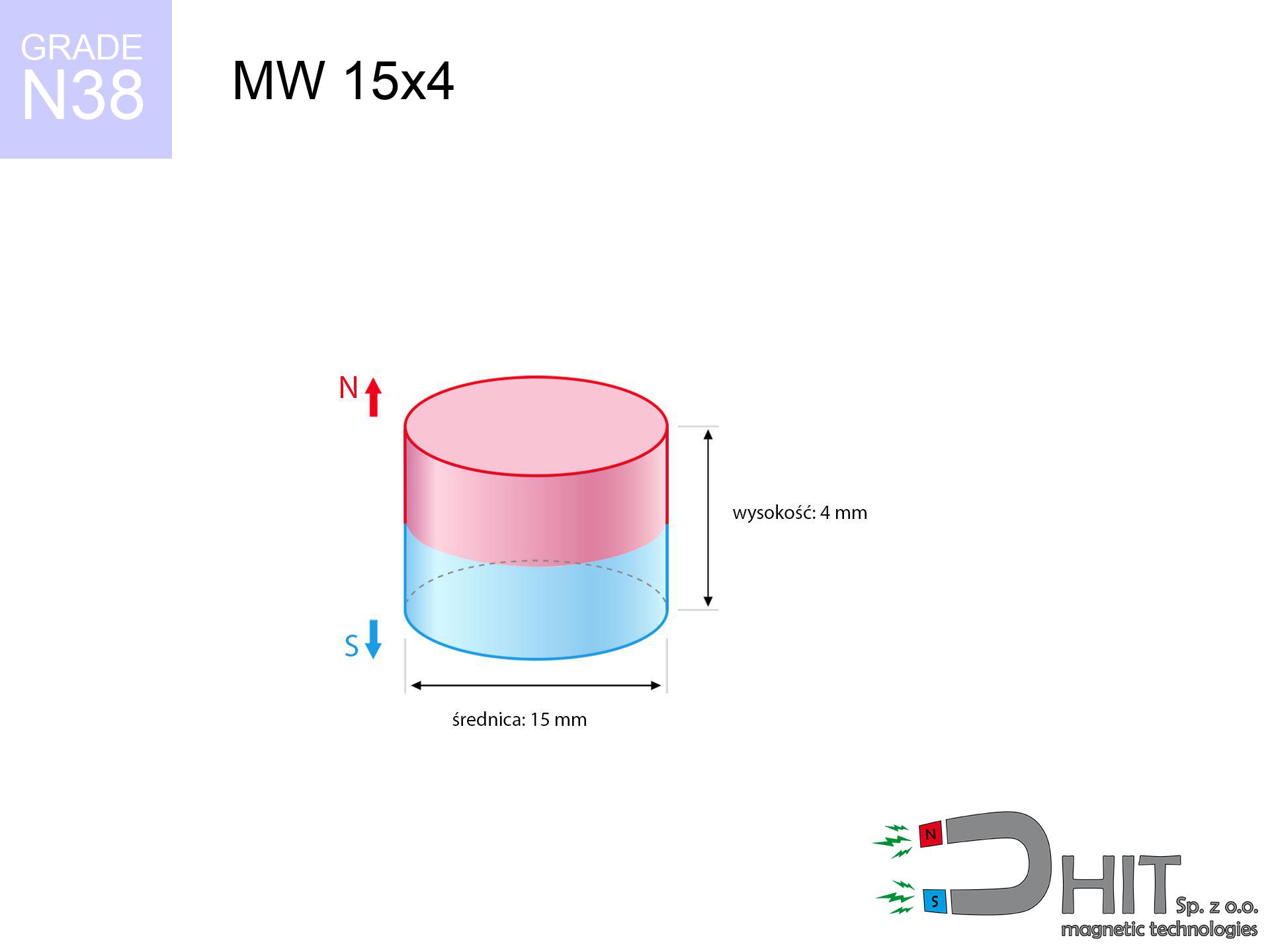
MW 15x4 / N38 - cylindrical magnet
cylindrical magnet
Catalog no 010030
GTIN/EAN: 5906301810292
Diameter Ø
15 mm [±0,1 mm]
Height
4 mm [±0,1 mm]
Weight
5.3 g
Magnetization Direction
↑ axial
Load capacity
4.22 kg / 41.38 N
Magnetic Induction
291.60 mT / 2916 Gs
Coating
[NiCuNi] Nickel
1.968 ZŁ with VAT / pcs + price for transport
1.600 ZŁ net + 23% VAT / pcs
bulk discounts:
Need more?
Give us a call
+48 22 499 98 98
if you prefer contact us through
our online form
the contact page.
Weight and appearance of a magnet can be tested with our
our magnetic calculator.
Same-day shipping for orders placed before 14:00.
Technical of the product - MW 15x4 / N38 - cylindrical magnet
Specification / characteristics - MW 15x4 / N38 - cylindrical magnet
| properties | values |
|---|---|
| Cat. no. | 010030 |
| GTIN/EAN | 5906301810292 |
| Production/Distribution | Dhit sp. z o.o. |
| Country of origin | Poland / China / Germany |
| Customs code | 85059029 |
| Diameter Ø | 15 mm [±0,1 mm] |
| Height | 4 mm [±0,1 mm] |
| Weight | 5.3 g |
| Magnetization Direction | ↑ axial |
| Load capacity ~ ? | 4.22 kg / 41.38 N |
| Magnetic Induction ~ ? | 291.60 mT / 2916 Gs |
| Coating | [NiCuNi] Nickel |
| Manufacturing Tolerance | ±0.1 mm |
Magnetic properties of material N38
| properties | values | units |
|---|---|---|
| remenance Br [min. - max.] ? | 12.2-12.6 | kGs |
| remenance Br [min. - max.] ? | 1220-1260 | mT |
| coercivity bHc ? | 10.8-11.5 | kOe |
| coercivity bHc ? | 860-915 | kA/m |
| actual internal force iHc | ≥ 12 | kOe |
| actual internal force iHc | ≥ 955 | kA/m |
| energy density [min. - max.] ? | 36-38 | BH max MGOe |
| energy density [min. - max.] ? | 287-303 | BH max KJ/m |
| max. temperature ? | ≤ 80 | °C |
Physical properties of sintered neodymium magnets Nd2Fe14B at 20°C
| properties | values | units |
|---|---|---|
| Vickers hardness | ≥550 | Hv |
| Density | ≥7.4 | g/cm3 |
| Curie Temperature TC | 312 - 380 | °C |
| Curie Temperature TF | 593 - 716 | °F |
| Specific resistance | 150 | μΩ⋅cm |
| Bending strength | 250 | MPa |
| Compressive strength | 1000~1100 | MPa |
| Thermal expansion parallel (∥) to orientation (M) | (3-4) x 10-6 | °C-1 |
| Thermal expansion perpendicular (⊥) to orientation (M) | -(1-3) x 10-6 | °C-1 |
| Young's modulus | 1.7 x 10⁴ | kg/mm² |
Engineering analysis of the magnet - report
The following data represent the result of a mathematical calculation. Results rely on algorithms for the class Nd2Fe14B. Actual performance may deviate from the simulation results. Treat these data as a reference point when designing systems.
Table 1: Static pull force (force vs distance) - interaction chart
MW 15x4 / N38
| Distance (mm) | Induction (Gauss) / mT | Pull Force (kg/lbs/g/N) | Risk Status |
|---|---|---|---|
| 0 mm |
2915 Gs
291.5 mT
|
4.22 kg / 9.30 lbs
4220.0 g / 41.4 N
|
medium risk |
| 1 mm |
2620 Gs
262.0 mT
|
3.41 kg / 7.51 lbs
3408.2 g / 33.4 N
|
medium risk |
| 2 mm |
2276 Gs
227.6 mT
|
2.57 kg / 5.67 lbs
2571.6 g / 25.2 N
|
medium risk |
| 3 mm |
1928 Gs
192.8 mT
|
1.85 kg / 4.07 lbs
1845.5 g / 18.1 N
|
low risk |
| 5 mm |
1324 Gs
132.4 mT
|
0.87 kg / 1.92 lbs
870.3 g / 8.5 N
|
low risk |
| 10 mm |
505 Gs
50.5 mT
|
0.13 kg / 0.28 lbs
126.7 g / 1.2 N
|
low risk |
| 15 mm |
222 Gs
22.2 mT
|
0.02 kg / 0.05 lbs
24.4 g / 0.2 N
|
low risk |
| 20 mm |
113 Gs
11.3 mT
|
0.01 kg / 0.01 lbs
6.3 g / 0.1 N
|
low risk |
| 30 mm |
40 Gs
4.0 mT
|
0.00 kg / 0.00 lbs
0.8 g / 0.0 N
|
low risk |
| 50 mm |
10 Gs
1.0 mT
|
0.00 kg / 0.00 lbs
0.0 g / 0.0 N
|
low risk |
Table 2: Slippage capacity (vertical surface)
MW 15x4 / N38
| Distance (mm) | Friction coefficient | Pull Force (kg/lbs/g/N) |
|---|---|---|
| 0 mm | Stal (~0.2) |
0.84 kg / 1.86 lbs
844.0 g / 8.3 N
|
| 1 mm | Stal (~0.2) |
0.68 kg / 1.50 lbs
682.0 g / 6.7 N
|
| 2 mm | Stal (~0.2) |
0.51 kg / 1.13 lbs
514.0 g / 5.0 N
|
| 3 mm | Stal (~0.2) |
0.37 kg / 0.82 lbs
370.0 g / 3.6 N
|
| 5 mm | Stal (~0.2) |
0.17 kg / 0.38 lbs
174.0 g / 1.7 N
|
| 10 mm | Stal (~0.2) |
0.03 kg / 0.06 lbs
26.0 g / 0.3 N
|
| 15 mm | Stal (~0.2) |
0.00 kg / 0.01 lbs
4.0 g / 0.0 N
|
| 20 mm | Stal (~0.2) |
0.00 kg / 0.00 lbs
2.0 g / 0.0 N
|
| 30 mm | Stal (~0.2) |
0.00 kg / 0.00 lbs
0.0 g / 0.0 N
|
| 50 mm | Stal (~0.2) |
0.00 kg / 0.00 lbs
0.0 g / 0.0 N
|
Table 3: Wall mounting (sliding) - behavior on slippery surfaces
MW 15x4 / N38
| Surface type | Friction coefficient / % Mocy | Max load (kg/lbs/g/N) |
|---|---|---|
| Raw steel |
µ = 0.3
30% Nominalnej Siły
|
1.27 kg / 2.79 lbs
1266.0 g / 12.4 N
|
| Painted steel (standard) |
µ = 0.2
20% Nominalnej Siły
|
0.84 kg / 1.86 lbs
844.0 g / 8.3 N
|
| Oily/slippery steel |
µ = 0.1
10% Nominalnej Siły
|
0.42 kg / 0.93 lbs
422.0 g / 4.1 N
|
| Magnet with anti-slip rubber |
µ = 0.5
50% Nominalnej Siły
|
2.11 kg / 4.65 lbs
2110.0 g / 20.7 N
|
Table 4: Material efficiency (saturation) - sheet metal selection
MW 15x4 / N38
| Steel thickness (mm) | % power | Real pull force (kg/lbs/g/N) |
|---|---|---|
| 0.5 mm |
|
0.42 kg / 0.93 lbs
422.0 g / 4.1 N
|
| 1 mm |
|
1.06 kg / 2.33 lbs
1055.0 g / 10.3 N
|
| 2 mm |
|
2.11 kg / 4.65 lbs
2110.0 g / 20.7 N
|
| 3 mm |
|
3.17 kg / 6.98 lbs
3165.0 g / 31.0 N
|
| 5 mm |
|
4.22 kg / 9.30 lbs
4220.0 g / 41.4 N
|
| 10 mm |
|
4.22 kg / 9.30 lbs
4220.0 g / 41.4 N
|
| 11 mm |
|
4.22 kg / 9.30 lbs
4220.0 g / 41.4 N
|
| 12 mm |
|
4.22 kg / 9.30 lbs
4220.0 g / 41.4 N
|
Table 5: Thermal stability (stability) - thermal limit
MW 15x4 / N38
| Ambient temp. (°C) | Power loss | Remaining pull (kg/lbs/g/N) | Status |
|---|---|---|---|
| 20 °C | 0.0% |
4.22 kg / 9.30 lbs
4220.0 g / 41.4 N
|
OK |
| 40 °C | -2.2% |
4.13 kg / 9.10 lbs
4127.2 g / 40.5 N
|
OK |
| 60 °C | -4.4% |
4.03 kg / 8.89 lbs
4034.3 g / 39.6 N
|
|
| 80 °C | -6.6% |
3.94 kg / 8.69 lbs
3941.5 g / 38.7 N
|
|
| 100 °C | -28.8% |
3.00 kg / 6.62 lbs
3004.6 g / 29.5 N
|
Table 6: Magnet-Magnet interaction (repulsion) - field range
MW 15x4 / N38
| Gap (mm) | Attraction (kg/lbs) (N-S) | Lateral Force (kg/lbs/g/N) | Repulsion (kg/lbs) (N-N) |
|---|---|---|---|
| 0 mm |
9.26 kg / 20.41 lbs
4 518 Gs
|
1.39 kg / 3.06 lbs
1389 g / 13.6 N
|
N/A |
| 1 mm |
8.40 kg / 18.53 lbs
5 555 Gs
|
1.26 kg / 2.78 lbs
1261 g / 12.4 N
|
7.56 kg / 16.68 lbs
~0 Gs
|
| 2 mm |
7.48 kg / 16.48 lbs
5 239 Gs
|
1.12 kg / 2.47 lbs
1122 g / 11.0 N
|
6.73 kg / 14.84 lbs
~0 Gs
|
| 3 mm |
6.54 kg / 14.42 lbs
4 901 Gs
|
0.98 kg / 2.16 lbs
981 g / 9.6 N
|
5.89 kg / 12.98 lbs
~0 Gs
|
| 5 mm |
4.80 kg / 10.59 lbs
4 200 Gs
|
0.72 kg / 1.59 lbs
721 g / 7.1 N
|
4.32 kg / 9.53 lbs
~0 Gs
|
| 10 mm |
1.91 kg / 4.21 lbs
2 648 Gs
|
0.29 kg / 0.63 lbs
286 g / 2.8 N
|
1.72 kg / 3.79 lbs
~0 Gs
|
| 20 mm |
0.28 kg / 0.61 lbs
1 010 Gs
|
0.04 kg / 0.09 lbs
42 g / 0.4 N
|
0.25 kg / 0.55 lbs
~0 Gs
|
| 50 mm |
0.00 kg / 0.01 lbs
128 Gs
|
0.00 kg / 0.00 lbs
1 g / 0.0 N
|
0.00 kg / 0.00 lbs
~0 Gs
|
| 60 mm |
0.00 kg / 0.00 lbs
79 Gs
|
0.00 kg / 0.00 lbs
0 g / 0.0 N
|
0.00 kg / 0.00 lbs
~0 Gs
|
| 70 mm |
0.00 kg / 0.00 lbs
52 Gs
|
0.00 kg / 0.00 lbs
0 g / 0.0 N
|
0.00 kg / 0.00 lbs
~0 Gs
|
| 80 mm |
0.00 kg / 0.00 lbs
36 Gs
|
0.00 kg / 0.00 lbs
0 g / 0.0 N
|
0.00 kg / 0.00 lbs
~0 Gs
|
| 90 mm |
0.00 kg / 0.00 lbs
26 Gs
|
0.00 kg / 0.00 lbs
0 g / 0.0 N
|
0.00 kg / 0.00 lbs
~0 Gs
|
| 100 mm |
0.00 kg / 0.00 lbs
19 Gs
|
0.00 kg / 0.00 lbs
0 g / 0.0 N
|
0.00 kg / 0.00 lbs
~0 Gs
|
Table 7: Safety (HSE) (electronics) - warnings
MW 15x4 / N38
| Object / Device | Limit (Gauss) / mT | Safe distance |
|---|---|---|
| Pacemaker | 5 Gs (0.5 mT) | 6.5 cm |
| Hearing aid | 10 Gs (1.0 mT) | 5.0 cm |
| Mechanical watch | 20 Gs (2.0 mT) | 4.0 cm |
| Mobile device | 40 Gs (4.0 mT) | 3.0 cm |
| Remote | 50 Gs (5.0 mT) | 3.0 cm |
| Payment card | 400 Gs (40.0 mT) | 1.5 cm |
| HDD hard drive | 600 Gs (60.0 mT) | 1.0 cm |
Table 8: Dynamics (cracking risk) - collision effects
MW 15x4 / N38
| Start from (mm) | Speed (km/h) | Energy (J) | Predicted outcome |
|---|---|---|---|
| 10 mm |
28.99 km/h
(8.05 m/s)
|
0.17 J | |
| 30 mm |
49.30 km/h
(13.69 m/s)
|
0.50 J | |
| 50 mm |
63.63 km/h
(17.68 m/s)
|
0.83 J | |
| 100 mm |
89.99 km/h
(25.00 m/s)
|
1.66 J |
Table 9: Anti-corrosion coating durability
MW 15x4 / N38
| Technical parameter | Value / Description |
|---|---|
| Coating type | [NiCuNi] Nickel |
| Layer structure | Nickel - Copper - Nickel |
| Layer thickness | 10-20 µm |
| Salt spray test (SST) ? | 24 h |
| Recommended environment | Indoors only (dry) |
Table 10: Electrical data (Flux)
MW 15x4 / N38
| Parameter | Value | SI Unit / Description |
|---|---|---|
| Magnetic Flux | 5 659 Mx | 56.6 µWb |
| Pc Coefficient | 0.37 | Low (Flat) |
Table 11: Hydrostatics and buoyancy
MW 15x4 / N38
| Environment | Effective steel pull | Effect |
|---|---|---|
| Air (land) | 4.22 kg | Standard |
| Water (riverbed) |
4.83 kg
(+0.61 kg buoyancy gain)
|
+14.5% |
1. Sliding resistance
*Caution: On a vertical surface, the magnet retains just a fraction of its nominal pull.
2. Efficiency vs thickness
*Thin steel (e.g. computer case) severely limits the holding force.
3. Thermal stability
*For N38 material, the safety limit is 80°C.
4. Demagnetization curve and operating point (B-H)
chart generated for the permeance coefficient Pc (Permeance Coefficient) = 0.37
This simulation demonstrates the magnetic stability of the selected magnet under specific geometric conditions. The solid red line represents the demagnetization curve (material potential), while the dashed blue line is the load line based on the magnet's geometry. The Pc (Permeance Coefficient), also known as the load line slope, is a dimensionless value that describes the relationship between the magnet's shape and its magnetic stability. The intersection of these two lines (the black dot) is the operating point — it determines the actual magnetic flux density generated by the magnet in this specific configuration. A higher Pc value means the magnet is more 'slender' (tall relative to its area), resulting in a higher operating point and better resistance to irreversible demagnetization caused by external fields or temperature. A value of 0.42 is relatively low (typical for flat magnets), meaning the operating point is closer to the 'knee' of the curve — caution is advised when operating at temperatures near the maximum limit to avoid strength loss.
Chemical composition
| iron (Fe) | 64% – 68% |
| neodymium (Nd) | 29% – 32% |
| boron (B) | 1.1% – 1.2% |
| dysprosium (Dy) | 0.5% – 2.0% |
| coating (Ni-Cu-Ni) | < 0.05% |
Sustainability
| recyclability (EoL) | 100% |
| recycled raw materials | ~10% (pre-cons) |
| carbon footprint | low / zredukowany |
| waste code (EWC) | 16 02 16 |
Other products
![UMGGZ 88x8.5 [M8] GZ / N38 - rubber magnetic holder external thread](https://cdn3.dhit.pl/graphics/products/umg-88x8.5-m8-gz-waf.jpg "UMGGZ 88x8.5 [M8] GZ / N38 - rubber magnetic holder external thread")

![SM 25x375 [2xM8] / N52 - magnetic separator](https://cdn3.dhit.pl/graphics/products/sm-25x375-2xm8-soh.jpg "SM 25x375 [2xM8] / N52 - magnetic separator")

Advantages as well as disadvantages of rare earth magnets.
Benefits
- They virtually do not lose power, because even after 10 years the decline in efficiency is only ~1% (according to literature),
- They possess excellent resistance to magnetism drop due to external magnetic sources,
- Thanks to the glossy finish, the surface of Ni-Cu-Ni, gold-plated, or silver gives an clean appearance,
- Magnets possess very high magnetic induction on the outer layer,
- Thanks to resistance to high temperature, they are capable of working (depending on the form) even at temperatures up to 230°C and higher...
- Possibility of detailed modeling and adjusting to concrete conditions,
- Huge importance in advanced technology sectors – they serve a role in data components, motor assemblies, precision medical tools, and complex engineering applications.
- Compactness – despite small sizes they provide effective action, making them ideal for precision applications
Limitations
- At strong impacts they can break, therefore we recommend placing them in steel cases. A metal housing provides additional protection against damage and increases the magnet's durability.
- NdFeB magnets lose force when exposed to high temperatures. After reaching 80°C, many of them experience permanent drop of strength (a factor is the shape and dimensions of the magnet). We offer magnets specially adapted to work at temperatures up to 230°C marked [AH], which are extremely resistant to heat
- Due to the susceptibility of magnets to corrosion in a humid environment, we advise using waterproof magnets made of rubber, plastic or other material resistant to moisture, in case of application outdoors
- Limited possibility of creating nuts in the magnet and complex forms - recommended is a housing - magnetic holder.
- Possible danger to health – tiny shards of magnets are risky, if swallowed, which is particularly important in the context of child safety. It is also worth noting that small components of these devices can be problematic in diagnostics medical in case of swallowing.
- Due to neodymium price, their price is higher than average,
Lifting parameters
Maximum magnetic pulling force – what affects it?
- with the use of a yoke made of low-carbon steel, ensuring full magnetic saturation
- with a cross-section of at least 10 mm
- with an polished touching surface
- without the slightest insulating layer between the magnet and steel
- under vertical application of breakaway force (90-degree angle)
- at temperature approx. 20 degrees Celsius
Key elements affecting lifting force
- Clearance – the presence of foreign body (paint, tape, air) acts as an insulator, which reduces capacity steeply (even by 50% at 0.5 mm).
- Direction of force – highest force is obtained only during perpendicular pulling. The force required to slide of the magnet along the plate is typically many times smaller (approx. 1/5 of the lifting capacity).
- Wall thickness – the thinner the sheet, the weaker the hold. Magnetic flux passes through the material instead of generating force.
- Steel type – mild steel gives the best results. Alloy admixtures reduce magnetic properties and lifting capacity.
- Surface condition – ground elements ensure maximum contact, which improves force. Uneven metal reduce efficiency.
- Temperature – temperature increase results in weakening of force. Check the maximum operating temperature for a given model.
Lifting capacity testing was carried out on a smooth plate of suitable thickness, under a perpendicular pulling force, whereas under parallel forces the lifting capacity is smaller. Additionally, even a small distance between the magnet and the plate lowers the holding force.
Warnings
Eye protection
Protect your eyes. Magnets can fracture upon uncontrolled impact, launching shards into the air. We recommend safety glasses.
Threat to electronics
Do not bring magnets close to a purse, computer, or TV. The magnetism can irreversibly ruin these devices and wipe information from cards.
Pinching danger
Protect your hands. Two large magnets will snap together immediately with a force of massive weight, destroying everything in their path. Exercise extreme caution!
Swallowing risk
Product intended for adults. Tiny parts can be swallowed, leading to severe trauma. Store out of reach of children and animals.
Compass and GPS
GPS units and mobile phones are extremely susceptible to magnetism. Close proximity with a powerful NdFeB magnet can permanently damage the internal compass in your phone.
Machining danger
Drilling and cutting of NdFeB material carries a risk of fire hazard. Neodymium dust oxidizes rapidly with oxygen and is difficult to extinguish.
Respect the power
Use magnets with awareness. Their immense force can shock even experienced users. Be vigilant and do not underestimate their force.
Heat sensitivity
Avoid heat. NdFeB magnets are sensitive to heat. If you need operation above 80°C, look for special high-temperature series (H, SH, UH).
ICD Warning
Patients with a ICD should keep an absolute distance from magnets. The magnetic field can stop the operation of the implant.
Warning for allergy sufferers
Warning for allergy sufferers: The Ni-Cu-Ni coating consists of nickel. If an allergic reaction appears, cease handling magnets and use protective gear.
Tabela kosztu i czasu dostawy
Płatność przed wysyłką:

GLS kurier
Przesyłka będzie u Ciebie za 2-3 dni
14.99 ZŁ

InPost Paczkomaty 24/7
Przesyłka będzie u Ciebie za 1-2 dni
12.30 ZŁ
Płatność przy odbiorze (pobranie):
GLS kurier
Przesyłka będzie u Ciebie za 1-2 dni
23.00 ZŁ
Rate the product
Your rating