
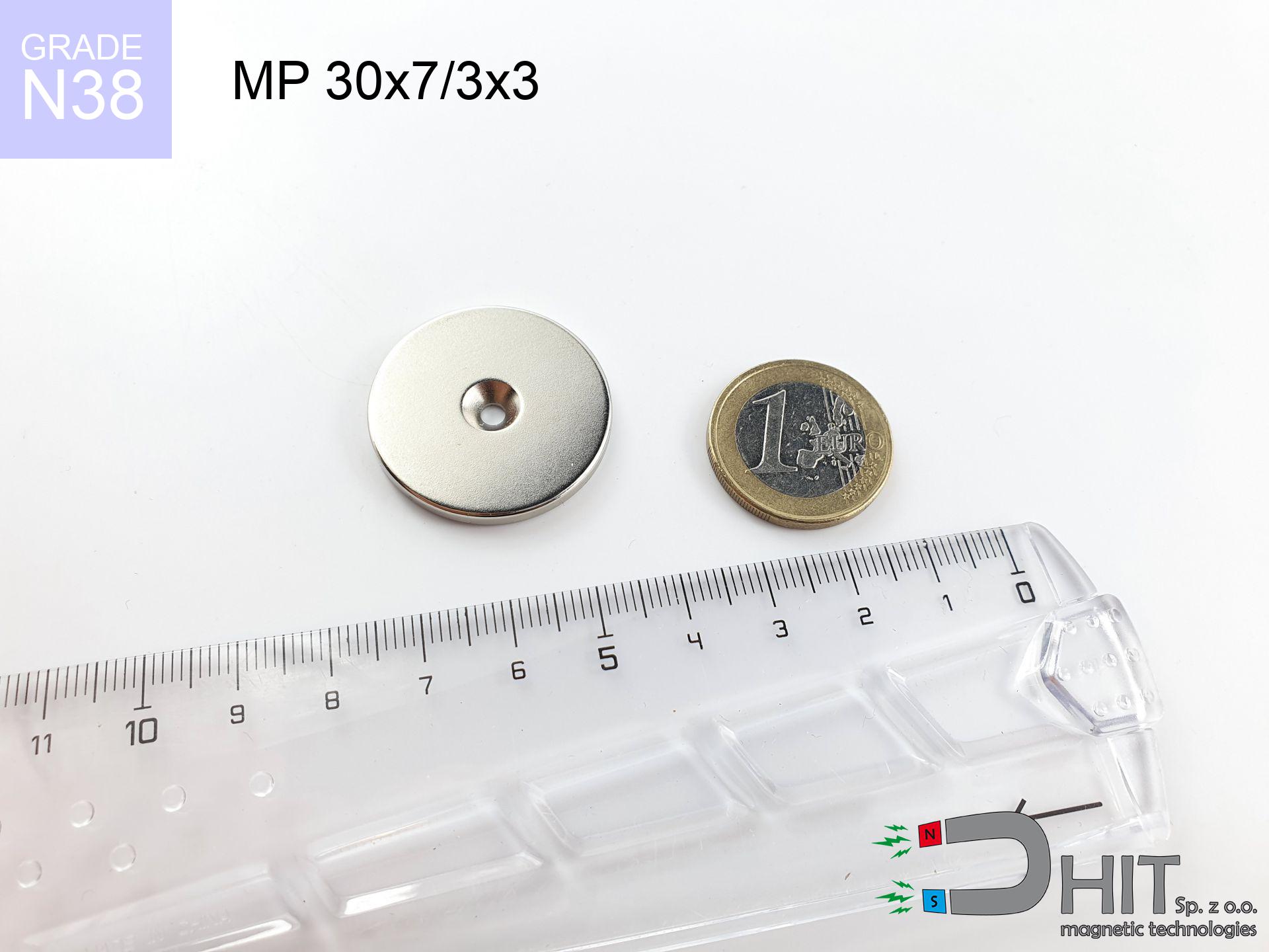
MP 30x7/3x3 / N38 - ring magnet
ring magnet
Catalog no 030250
GTIN/EAN: 5906301812265
Diameter
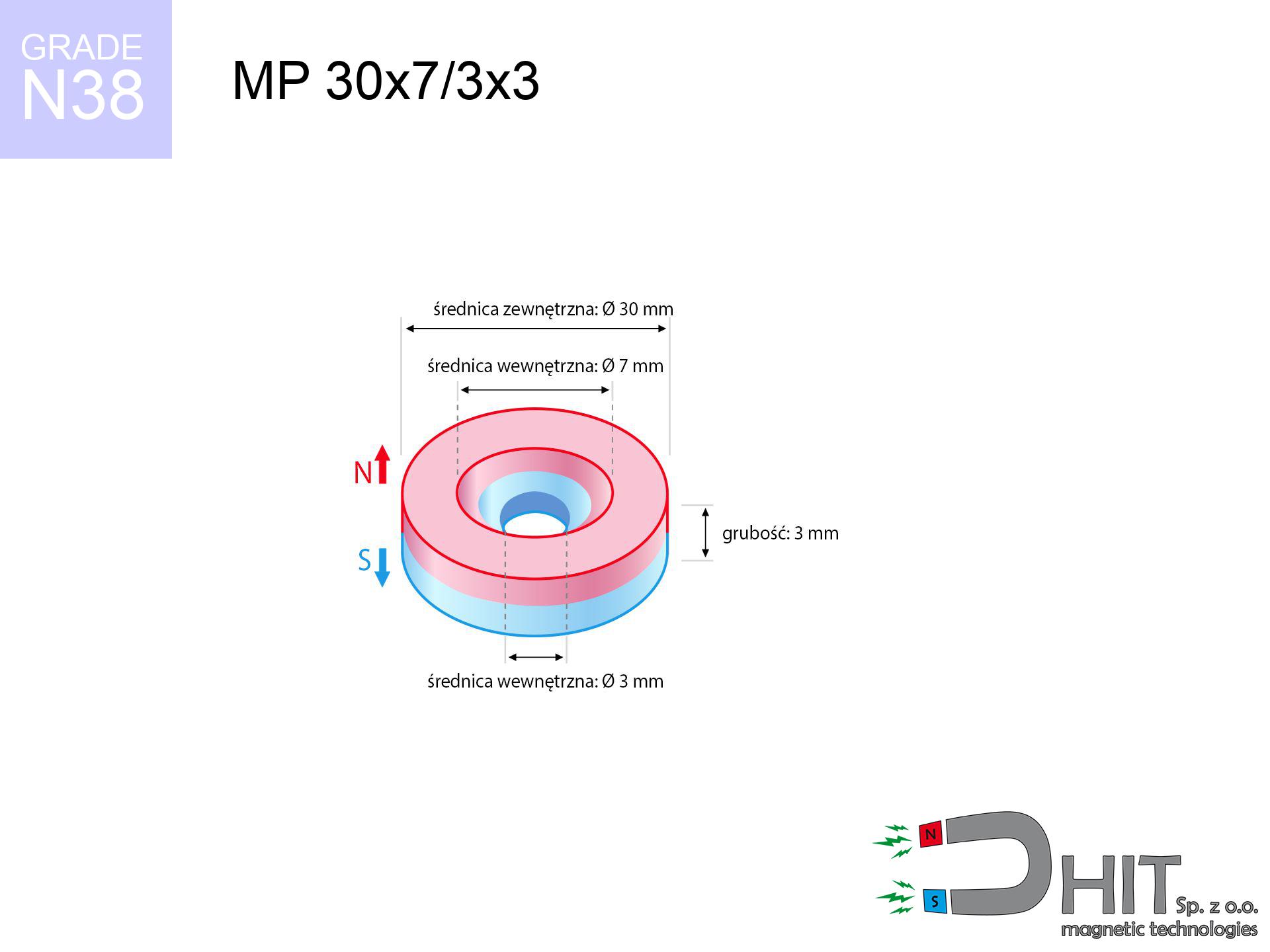
30 mm [±0,1 mm]
internal diameter Ø
7/3 mm [±0,1 mm]
Height
3 mm [±0,1 mm]
Weight
15.75 g
Magnetization Direction
↑ axial
Load capacity
3.64 kg / 35.69 N
Magnetic Induction
121.58 mT / 1216 Gs
Coating
[NiCuNi] Nickel
6.84 ZŁ with VAT / pcs + price for transport
5.56 ZŁ net + 23% VAT / pcs
bulk discounts:
Need more?Engineering report for this magnet
Full PDF analysis: pull and shear force, effect of distance, temperature and plate thickness, safety distances and the demagnetization curve.
Call us now
+48 22 499 98 98
or drop us a message by means of
request form
the contact section.
Weight along with appearance of neodymium magnets can be analyzed using our
force calculator.
Order by 14:00 and we’ll ship today!
Technical of the product - MP 30x7/3x3 / N38 - ring magnet
Specification / characteristics - MP 30x7/3x3 / N38 - ring magnet
| properties | values |
|---|---|
| Cat. no. | 030250 |
| GTIN/EAN | 5906301812265 |
| Production/Distribution | Dhit sp. z o.o. |
| Country of origin | Poland / China / Germany |
| Customs code | 85059029 |
| Diameter | 30 mm [±0,1 mm] |
| internal diameter Ø | 7/3 mm [±0,1 mm] |
| Height | 3 mm [±0,1 mm] |
| Weight | 15.75 g |
| Magnetization Direction | ↑ axial |
| Load capacity ~ ? | 3.64 kg / 35.69 N |
| Magnetic Induction ~ ? | 121.58 mT / 1216 Gs |
| Coating | [NiCuNi] Nickel |
| Manufacturing Tolerance | ±0.1 mm |
Magnetic properties of material N38
| properties | values | units |
|---|---|---|
| remenance Br [min. - max.] ? | 12.2-12.6 | kGs |
| remenance Br [min. - max.] ? | 1220-1260 | mT |
| coercivity bHc ? | 10.8-11.5 | kOe |
| coercivity bHc ? | 860-915 | kA/m |
| actual internal force iHc | ≥ 12 | kOe |
| actual internal force iHc | ≥ 955 | kA/m |
| energy density [min. - max.] ? | 36-38 | BH max MGOe |
| energy density [min. - max.] ? | 287-303 | BH max KJ/m |
| max. temperature ? | ≤ 80 | °C |
Physical properties of sintered neodymium magnets Nd2Fe14B at 20°C
| properties | values | units |
|---|---|---|
| Vickers hardness | ≥550 | Hv |
| Density | ≥7.4 | g/cm3 |
| Curie Temperature TC | 312 - 380 | °C |
| Curie Temperature TF | 593 - 716 | °F |
| Specific resistance | 150 | μΩ⋅cm |
| Bending strength | 250 | MPa |
| Compressive strength | 1000~1100 | MPa |
| Thermal expansion parallel (∥) to orientation (M) | (3-4) x 10-6 | °C-1 |
| Thermal expansion perpendicular (⊥) to orientation (M) | -(1-3) x 10-6 | °C-1 |
| Young's modulus | 1.7 x 10⁴ | kg/mm² |
Technical simulation of the magnet - data
The following values are the result of a mathematical analysis. Values were calculated on algorithms for the material Nd2Fe14B. Real-world performance may differ from theoretical values. Treat these calculations as a reference point when designing systems.
Table 1: Static pull force (pull vs distance) - interaction chart
MP 30x7/3x3 / N38
| Distance (mm) | Induction (Gauss) / mT | Pull Force (kg/lbs/g/N) | Risk Status |
|---|---|---|---|
| 0 mm |
1039 Gs
103.9 mT
|
3.64 kg / 8.02 LBS
3640.0 g / 35.7 N
|
medium risk |
| 1 mm |
1015 Gs
101.5 mT
|
3.48 kg / 7.67 LBS
3477.6 g / 34.1 N
|
medium risk |
| 2 mm |
980 Gs
98.0 mT
|
3.24 kg / 7.14 LBS
3240.7 g / 31.8 N
|
medium risk |
| 3 mm |
936 Gs
93.6 mT
|
2.95 kg / 6.51 LBS
2951.6 g / 29.0 N
|
medium risk |
| 5 mm |
827 Gs
82.7 mT
|
2.31 kg / 5.08 LBS
2305.8 g / 22.6 N
|
medium risk |
| 10 mm |
539 Gs
53.9 mT
|
0.98 kg / 2.16 LBS
981.0 g / 9.6 N
|
weak grip |
| 15 mm |
329 Gs
32.9 mT
|
0.37 kg / 0.80 LBS
365.1 g / 3.6 N
|
weak grip |
| 20 mm |
202 Gs
20.2 mT
|
0.14 kg / 0.30 LBS
137.9 g / 1.4 N
|
weak grip |
| 30 mm |
85 Gs
8.5 mT
|
0.02 kg / 0.05 LBS
24.6 g / 0.2 N
|
weak grip |
| 50 mm |
23 Gs
2.3 mT
|
0.00 kg / 0.00 LBS
1.8 g / 0.0 N
|
weak grip |
Table 2: Slippage capacity (vertical surface)
MP 30x7/3x3 / N38
| Distance (mm) | Friction coefficient | Pull Force (kg/lbs/g/N) |
|---|---|---|
| 0 mm | Stal (~0.2) |
0.73 kg / 1.60 LBS
728.0 g / 7.1 N
|
| 1 mm | Stal (~0.2) |
0.70 kg / 1.53 LBS
696.0 g / 6.8 N
|
| 2 mm | Stal (~0.2) |
0.65 kg / 1.43 LBS
648.0 g / 6.4 N
|
| 3 mm | Stal (~0.2) |
0.59 kg / 1.30 LBS
590.0 g / 5.8 N
|
| 5 mm | Stal (~0.2) |
0.46 kg / 1.02 LBS
462.0 g / 4.5 N
|
| 10 mm | Stal (~0.2) |
0.20 kg / 0.43 LBS
196.0 g / 1.9 N
|
| 15 mm | Stal (~0.2) |
0.07 kg / 0.16 LBS
74.0 g / 0.7 N
|
| 20 mm | Stal (~0.2) |
0.03 kg / 0.06 LBS
28.0 g / 0.3 N
|
| 30 mm | Stal (~0.2) |
0.00 kg / 0.01 LBS
4.0 g / 0.0 N
|
| 50 mm | Stal (~0.2) |
0.00 kg / 0.00 LBS
0.0 g / 0.0 N
|
Table 3: Wall mounting (sliding) - behavior on slippery surfaces
MP 30x7/3x3 / N38
| Surface type | Friction coefficient / % Mocy | Max load (kg/lbs/g/N) |
|---|---|---|
| Raw steel |
µ = 0.3
30% Nominalnej Siły
|
1.09 kg / 2.41 LBS
1092.0 g / 10.7 N
|
| Painted steel (standard) |
µ = 0.2
20% Nominalnej Siły
|
0.73 kg / 1.60 LBS
728.0 g / 7.1 N
|
| Oily/slippery steel |
µ = 0.1
10% Nominalnej Siły
|
0.36 kg / 0.80 LBS
364.0 g / 3.6 N
|
| Magnet with anti-slip rubber |
µ = 0.5
50% Nominalnej Siły
|
1.82 kg / 4.01 LBS
1820.0 g / 17.9 N
|
Table 4: Material efficiency (saturation) - power losses
MP 30x7/3x3 / N38
| Steel thickness (mm) | % power | Real pull force (kg/lbs/g/N) |
|---|---|---|
| 0.5 mm |
|
0.36 kg / 0.80 LBS
364.0 g / 3.6 N
|
| 1 mm |
|
0.91 kg / 2.01 LBS
910.0 g / 8.9 N
|
| 2 mm |
|
1.82 kg / 4.01 LBS
1820.0 g / 17.9 N
|
| 3 mm |
|
2.73 kg / 6.02 LBS
2730.0 g / 26.8 N
|
| 5 mm |
|
3.64 kg / 8.02 LBS
3640.0 g / 35.7 N
|
| 10 mm |
|
3.64 kg / 8.02 LBS
3640.0 g / 35.7 N
|
| 11 mm |
|
3.64 kg / 8.02 LBS
3640.0 g / 35.7 N
|
| 12 mm |
|
3.64 kg / 8.02 LBS
3640.0 g / 35.7 N
|
Table 5: Thermal resistance (stability) - thermal limit
MP 30x7/3x3 / N38
| Ambient temp. (°C) | Power loss | Remaining pull (kg/lbs/g/N) | Status |
|---|---|---|---|
| 20 °C | 0.0% |
3.64 kg / 8.02 LBS
3640.0 g / 35.7 N
|
OK |
| 40 °C | -2.2% |
3.56 kg / 7.85 LBS
3559.9 g / 34.9 N
|
OK |
| 60 °C | -4.4% |
3.48 kg / 7.67 LBS
3479.8 g / 34.1 N
|
|
| 80 °C | -6.6% |
3.40 kg / 7.50 LBS
3399.8 g / 33.4 N
|
|
| 100 °C | -28.8% |
2.59 kg / 5.71 LBS
2591.7 g / 25.4 N
|
Table 6: Magnet-Magnet interaction (attraction) - forces in the system
MP 30x7/3x3 / N38
| Gap (mm) | Attraction (kg/lbs) (N-S) | Lateral Force (kg/lbs/g/N) | Repulsion (kg/lbs) (N-N) |
|---|---|---|---|
| 0 mm |
3.96 kg / 8.73 LBS
1 995 Gs
|
0.59 kg / 1.31 LBS
594 g / 5.8 N
|
N/A |
| 1 mm |
3.88 kg / 8.56 LBS
2 058 Gs
|
0.58 kg / 1.28 LBS
582 g / 5.7 N
|
3.49 kg / 7.70 LBS
~0 Gs
|
| 2 mm |
3.78 kg / 8.34 LBS
2 031 Gs
|
0.57 kg / 1.25 LBS
567 g / 5.6 N
|
3.40 kg / 7.50 LBS
~0 Gs
|
| 3 mm |
3.66 kg / 8.07 LBS
1 998 Gs
|
0.55 kg / 1.21 LBS
549 g / 5.4 N
|
3.30 kg / 7.26 LBS
~0 Gs
|
| 5 mm |
3.37 kg / 7.43 LBS
1 918 Gs
|
0.51 kg / 1.12 LBS
506 g / 5.0 N
|
3.04 kg / 6.69 LBS
~0 Gs
|
| 10 mm |
2.51 kg / 5.53 LBS
1 654 Gs
|
0.38 kg / 0.83 LBS
376 g / 3.7 N
|
2.26 kg / 4.97 LBS
~0 Gs
|
| 20 mm |
1.07 kg / 2.35 LBS
1 079 Gs
|
0.16 kg / 0.35 LBS
160 g / 1.6 N
|
0.96 kg / 2.12 LBS
~0 Gs
|
| 50 mm |
0.06 kg / 0.13 LBS
258 Gs
|
0.01 kg / 0.02 LBS
9 g / 0.1 N
|
0.05 kg / 0.12 LBS
~0 Gs
|
| 60 mm |
0.03 kg / 0.06 LBS
171 Gs
|
0.00 kg / 0.01 LBS
4 g / 0.0 N
|
0.02 kg / 0.05 LBS
~0 Gs
|
| 70 mm |
0.01 kg / 0.03 LBS
118 Gs
|
0.00 kg / 0.00 LBS
2 g / 0.0 N
|
0.01 kg / 0.03 LBS
~0 Gs
|
| 80 mm |
0.01 kg / 0.01 LBS
84 Gs
|
0.00 kg / 0.00 LBS
1 g / 0.0 N
|
0.00 kg / 0.00 LBS
~0 Gs
|
| 90 mm |
0.00 kg / 0.01 LBS
62 Gs
|
0.00 kg / 0.00 LBS
1 g / 0.0 N
|
0.00 kg / 0.00 LBS
~0 Gs
|
| 100 mm |
0.00 kg / 0.00 LBS
47 Gs
|
0.00 kg / 0.00 LBS
0 g / 0.0 N
|
0.00 kg / 0.00 LBS
~0 Gs
|
Table 7: Safety (HSE) (implants) - precautionary measures
MP 30x7/3x3 / N38
| Object / Device | Limit (Gauss) / mT | Safe distance |
|---|---|---|
| Pacemaker | 5 Gs (0.5 mT) | 9.0 cm |
| Hearing aid | 10 Gs (1.0 mT) | 7.0 cm |
| Mechanical watch | 20 Gs (2.0 mT) | 5.5 cm |
| Mobile device | 40 Gs (4.0 mT) | 4.5 cm |
| Remote | 50 Gs (5.0 mT) | 4.0 cm |
| Payment card | 400 Gs (40.0 mT) | 1.5 cm |
| HDD hard drive | 600 Gs (60.0 mT) | 1.0 cm |
Table 8: Impact energy (kinetic energy) - collision effects
MP 30x7/3x3 / N38
| Start from (mm) | Speed (km/h) | Energy (J) | Predicted outcome |
|---|---|---|---|
| 10 mm |
17.73 km/h
(4.92 m/s)
|
0.19 J | |
| 30 mm |
26.67 km/h
(7.41 m/s)
|
0.43 J | |
| 50 mm |
34.29 km/h
(9.53 m/s)
|
0.71 J | |
| 100 mm |
48.48 km/h
(13.47 m/s)
|
1.43 J |
Table 9: Surface protection spec
MP 30x7/3x3 / N38
| Technical parameter | Value / Description |
|---|---|
| Coating type | [NiCuNi] Nickel |
| Layer structure | Nickel - Copper - Nickel |
| Layer thickness | 10-20 µm |
| Salt spray test (SST) ? | 24 h |
| Recommended environment | Indoors only (dry) |
Table 10: Electrical data (Pc)
MP 30x7/3x3 / N38
| Parameter | Value | SI Unit / Description |
|---|---|---|
| Magnetic Flux | 8 395 Mx | 84.0 µWb |
| Pc Coefficient | 0.13 | Low (Flat) |
Table 11: Underwater work (magnet fishing)
MP 30x7/3x3 / N38
| Environment | Effective steel pull | Effect |
|---|---|---|
| Air (land) | 3.64 kg | Standard |
| Water (riverbed) |
4.17 kg
(+0.53 kg buoyancy gain)
|
+14.5% |
1. Wall mount (shear)
*Caution: On a vertical surface, the magnet holds only approx. 20-30% of its nominal pull.
2. Steel thickness impact
*Thin metal sheet (e.g. computer case) drastically weakens the holding force.
3. Heat tolerance
*For N38 grade, the max working temp is 80°C.
4. Demagnetization curve and operating point (B-H)
chart generated for the permeance coefficient Pc (Permeance Coefficient) = 0.13
The chart above illustrates the magnetic characteristics of the material within the second quadrant of the hysteresis loop. The solid red line represents the demagnetization curve (material potential), while the dashed blue line is the load line based on the magnet's geometry. The Pc (Permeance Coefficient), also known as the load line slope, is a dimensionless value that describes the relationship between the magnet's shape and its magnetic stability. The intersection of these two lines (the black dot) is the operating point — it determines the actual magnetic flux density generated by the magnet in this specific configuration. A higher Pc value means the magnet is more 'slender' (tall relative to its area), resulting in a higher operating point and better resistance to irreversible demagnetization caused by external fields or temperature. A value of 0.42 is relatively low (typical for flat magnets), meaning the operating point is closer to the 'knee' of the curve — caution is advised when operating at temperatures near the maximum limit to avoid strength loss.
Elemental analysis
| iron (Fe) | 64% – 68% |
| neodymium (Nd) | 29% – 32% |
| boron (B) | 1.1% – 1.2% |
| dysprosium (Dy) | 0.5% – 2.0% |
| coating (Ni-Cu-Ni) | < 0.05% |
Environmental data
| recyclability (EoL) | 100% |
| recycled raw materials | ~10% (pre-cons) |
| carbon footprint | low / zredukowany |
| waste code (EWC) | 16 02 16 |
See more deals

![UI 17.5x5 [C310] / N38 - badge holder](https://cdn3.dhit.pl/graphics/products/ui17.5x5-c310-rud.jpg "UI 17.5x5 [C310] / N38 - badge holder")


Advantages as well as disadvantages of Nd2Fe14B magnets.
Strengths
- They retain attractive force for around 10 years – the drop is just ~1% (based on simulations),
- They do not lose their magnetic properties even under external field action,
- By applying a smooth coating of silver, the element has an nice look,
- Magnetic induction on the working part of the magnet is impressive,
- Through (appropriate) combination of ingredients, they can achieve high thermal strength, enabling operation at temperatures reaching 230°C and above...
- In view of the potential of free molding and customization to specialized requirements, magnetic components can be produced in a broad palette of geometric configurations, which makes them more universal,
- Wide application in modern industrial fields – they are utilized in computer drives, electric motors, medical devices, as well as complex engineering applications.
- Thanks to their power density, small magnets offer high operating force, with minimal size,
Disadvantages
- To avoid cracks under impact, we recommend using special steel holders. Such a solution protects the magnet and simultaneously increases its durability.
- Neodymium magnets decrease their power under the influence of heating. As soon as 80°C is exceeded, many of them start losing their power. Therefore, we recommend our special magnets marked [AH], which maintain stability even at temperatures up to 230°C
- They oxidize in a humid environment - during use outdoors we suggest using waterproof magnets e.g. in rubber, plastic
- Limited ability of making nuts in the magnet and complex forms - preferred is casing - mounting mechanism.
- Possible danger resulting from small fragments of magnets can be dangerous, if swallowed, which gains importance in the context of child safety. Additionally, small elements of these devices are able to be problematic in diagnostics medical in case of swallowing.
- Due to neodymium price, their price is higher than average,
Pull force analysis
Maximum lifting force for a neodymium magnet – what affects it?
- on a plate made of mild steel, effectively closing the magnetic field
- whose thickness equals approx. 10 mm
- with a plane cleaned and smooth
- with direct contact (without impurities)
- during pulling in a direction perpendicular to the mounting surface
- at room temperature
Impact of factors on magnetic holding capacity in practice
- Distance (between the magnet and the plate), because even a microscopic clearance (e.g. 0.5 mm) can cause a decrease in force by up to 50% (this also applies to varnish, corrosion or debris).
- Load vector – maximum parameter is obtained only during perpendicular pulling. The shear force of the magnet along the surface is standardly many times smaller (approx. 1/5 of the lifting capacity).
- Plate thickness – too thin sheet causes magnetic saturation, causing part of the power to be lost into the air.
- Metal type – not every steel reacts the same. Alloy additives weaken the interaction with the magnet.
- Surface structure – the more even the plate, the larger the contact zone and higher the lifting capacity. Roughness acts like micro-gaps.
- Thermal factor – hot environment reduces magnetic field. Exceeding the limit temperature can permanently damage the magnet.
Lifting capacity was determined with the use of a steel plate with a smooth surface of suitable thickness (min. 20 mm), under vertically applied force, whereas under shearing force the holding force is lower. Additionally, even a small distance between the magnet and the plate lowers the load capacity.
Precautions when working with NdFeB magnets
Magnet fragility
NdFeB magnets are ceramic materials, meaning they are fragile like glass. Clashing of two magnets will cause them shattering into small pieces.
Mechanical processing
Fire hazard: Rare earth powder is explosive. Do not process magnets without safety gear as this risks ignition.
Finger safety
Watch your fingers. Two large magnets will snap together instantly with a force of massive weight, destroying anything in their path. Exercise extreme caution!
Cards and drives
Powerful magnetic fields can corrupt files on credit cards, HDDs, and storage devices. Keep a distance of at least 10 cm.
Thermal limits
Regular neodymium magnets (N-type) undergo demagnetization when the temperature goes above 80°C. The loss of strength is permanent.
This is not a toy
Adult use only. Small elements can be swallowed, causing intestinal necrosis. Store away from kids and pets.
Nickel coating and allergies
Studies show that nickel (the usual finish) is a strong allergen. If your skin reacts to metals, avoid direct skin contact or select coated magnets.
Medical implants
Patients with a heart stimulator have to maintain an safe separation from magnets. The magnetic field can disrupt the operation of the implant.
GPS Danger
An intense magnetic field negatively affects the operation of magnetometers in phones and navigation systems. Do not bring magnets close to a device to avoid damaging the sensors.
Handling rules
Handle with care. Neodymium magnets act from a long distance and connect with huge force, often quicker than you can react.
Tabela kosztu i czasu dostawy
Płatność przed wysyłką:

GLS kurier
Przesyłka będzie u Ciebie za 2-3 dni
14.99 ZŁ

InPost Paczkomaty 24/7
Przesyłka będzie u Ciebie za 1-2 dni
12.30 ZŁ
Płatność przy odbiorze (pobranie):
GLS kurier
Przesyłka będzie u Ciebie za 1-2 dni
23.00 ZŁ
Rate the product
Your rating