

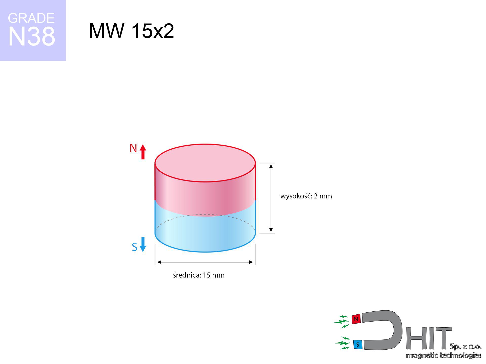
MW 15x2 / N38 - cylindrical magnet
cylindrical magnet
Catalog no 010028
GTIN/EAN: 5906301810278
Diameter Ø
15 mm [±0,1 mm]
Height
2 mm [±0,1 mm]
Weight
2.65 g
Magnetization Direction
↑ axial
Load capacity
1.51 kg / 14.84 N
Magnetic Induction
159.70 mT / 1597 Gs
Coating
[NiCuNi] Nickel
1.218 ZŁ with VAT / pcs + price for transport
0.990 ZŁ net + 23% VAT / pcs
bulk discounts:
Need more?
Call us
+48 888 99 98 98
alternatively let us know through
form
our website.
Strength along with structure of magnets can be calculated using our
magnetic mass calculator.
Orders placed before 14:00 will be shipped the same business day.
Technical specification of the product - MW 15x2 / N38 - cylindrical magnet
Specification / characteristics - MW 15x2 / N38 - cylindrical magnet
| properties | values |
|---|---|
| Cat. no. | 010028 |
| GTIN/EAN | 5906301810278 |
| Production/Distribution | Dhit sp. z o.o. |
| Country of origin | Poland / China / Germany |
| Customs code | 85059029 |
| Diameter Ø | 15 mm [±0,1 mm] |
| Height | 2 mm [±0,1 mm] |
| Weight | 2.65 g |
| Magnetization Direction | ↑ axial |
| Load capacity ~ ? | 1.51 kg / 14.84 N |
| Magnetic Induction ~ ? | 159.70 mT / 1597 Gs |
| Coating | [NiCuNi] Nickel |
| Manufacturing Tolerance | ±0.1 mm |
Magnetic properties of material N38
| properties | values | units |
|---|---|---|
| remenance Br [min. - max.] ? | 12.2-12.6 | kGs |
| remenance Br [min. - max.] ? | 1220-1260 | mT |
| coercivity bHc ? | 10.8-11.5 | kOe |
| coercivity bHc ? | 860-915 | kA/m |
| actual internal force iHc | ≥ 12 | kOe |
| actual internal force iHc | ≥ 955 | kA/m |
| energy density [min. - max.] ? | 36-38 | BH max MGOe |
| energy density [min. - max.] ? | 287-303 | BH max KJ/m |
| max. temperature ? | ≤ 80 | °C |
Physical properties of sintered neodymium magnets Nd2Fe14B at 20°C
| properties | values | units |
|---|---|---|
| Vickers hardness | ≥550 | Hv |
| Density | ≥7.4 | g/cm3 |
| Curie Temperature TC | 312 - 380 | °C |
| Curie Temperature TF | 593 - 716 | °F |
| Specific resistance | 150 | μΩ⋅cm |
| Bending strength | 250 | MPa |
| Compressive strength | 1000~1100 | MPa |
| Thermal expansion parallel (∥) to orientation (M) | (3-4) x 10-6 | °C-1 |
| Thermal expansion perpendicular (⊥) to orientation (M) | -(1-3) x 10-6 | °C-1 |
| Young's modulus | 1.7 x 10⁴ | kg/mm² |
Technical simulation of the assembly - data
These information are the result of a physical analysis. Values rely on models for the material Nd2Fe14B. Actual parameters might slightly differ. Please consider these data as a preliminary roadmap for designers.
Table 1: Static pull force (force vs distance) - interaction chart
MW 15x2 / N38
| Distance (mm) | Induction (Gauss) / mT | Pull Force (kg/lbs/g/N) | Risk Status |
|---|---|---|---|
| 0 mm |
1597 Gs
159.7 mT
|
1.51 kg / 3.33 lbs
1510.0 g / 14.8 N
|
weak grip |
| 1 mm |
1483 Gs
148.3 mT
|
1.30 kg / 2.87 lbs
1303.0 g / 12.8 N
|
weak grip |
| 2 mm |
1320 Gs
132.0 mT
|
1.03 kg / 2.28 lbs
1032.2 g / 10.1 N
|
weak grip |
| 3 mm |
1137 Gs
113.7 mT
|
0.77 kg / 1.69 lbs
765.0 g / 7.5 N
|
weak grip |
| 5 mm |
791 Gs
79.1 mT
|
0.37 kg / 0.82 lbs
370.8 g / 3.6 N
|
weak grip |
| 10 mm |
298 Gs
29.8 mT
|
0.05 kg / 0.12 lbs
52.5 g / 0.5 N
|
weak grip |
| 15 mm |
127 Gs
12.7 mT
|
0.01 kg / 0.02 lbs
9.6 g / 0.1 N
|
weak grip |
| 20 mm |
63 Gs
6.3 mT
|
0.00 kg / 0.01 lbs
2.4 g / 0.0 N
|
weak grip |
| 30 mm |
22 Gs
2.2 mT
|
0.00 kg / 0.00 lbs
0.3 g / 0.0 N
|
weak grip |
| 50 mm |
5 Gs
0.5 mT
|
0.00 kg / 0.00 lbs
0.0 g / 0.0 N
|
weak grip |
Table 2: Sliding hold (wall)
MW 15x2 / N38
| Distance (mm) | Friction coefficient | Pull Force (kg/lbs/g/N) |
|---|---|---|
| 0 mm | Stal (~0.2) |
0.30 kg / 0.67 lbs
302.0 g / 3.0 N
|
| 1 mm | Stal (~0.2) |
0.26 kg / 0.57 lbs
260.0 g / 2.6 N
|
| 2 mm | Stal (~0.2) |
0.21 kg / 0.45 lbs
206.0 g / 2.0 N
|
| 3 mm | Stal (~0.2) |
0.15 kg / 0.34 lbs
154.0 g / 1.5 N
|
| 5 mm | Stal (~0.2) |
0.07 kg / 0.16 lbs
74.0 g / 0.7 N
|
| 10 mm | Stal (~0.2) |
0.01 kg / 0.02 lbs
10.0 g / 0.1 N
|
| 15 mm | Stal (~0.2) |
0.00 kg / 0.00 lbs
2.0 g / 0.0 N
|
| 20 mm | Stal (~0.2) |
0.00 kg / 0.00 lbs
0.0 g / 0.0 N
|
| 30 mm | Stal (~0.2) |
0.00 kg / 0.00 lbs
0.0 g / 0.0 N
|
| 50 mm | Stal (~0.2) |
0.00 kg / 0.00 lbs
0.0 g / 0.0 N
|
Table 3: Vertical assembly (shearing) - behavior on slippery surfaces
MW 15x2 / N38
| Surface type | Friction coefficient / % Mocy | Max load (kg/lbs/g/N) |
|---|---|---|
| Raw steel |
µ = 0.3
30% Nominalnej Siły
|
0.45 kg / 1.00 lbs
453.0 g / 4.4 N
|
| Painted steel (standard) |
µ = 0.2
20% Nominalnej Siły
|
0.30 kg / 0.67 lbs
302.0 g / 3.0 N
|
| Oily/slippery steel |
µ = 0.1
10% Nominalnej Siły
|
0.15 kg / 0.33 lbs
151.0 g / 1.5 N
|
| Magnet with anti-slip rubber |
µ = 0.5
50% Nominalnej Siły
|
0.76 kg / 1.66 lbs
755.0 g / 7.4 N
|
Table 4: Steel thickness (saturation) - sheet metal selection
MW 15x2 / N38
| Steel thickness (mm) | % power | Real pull force (kg/lbs/g/N) |
|---|---|---|
| 0.5 mm |
|
0.15 kg / 0.33 lbs
151.0 g / 1.5 N
|
| 1 mm |
|
0.38 kg / 0.83 lbs
377.5 g / 3.7 N
|
| 2 mm |
|
0.76 kg / 1.66 lbs
755.0 g / 7.4 N
|
| 3 mm |
|
1.13 kg / 2.50 lbs
1132.5 g / 11.1 N
|
| 5 mm |
|
1.51 kg / 3.33 lbs
1510.0 g / 14.8 N
|
| 10 mm |
|
1.51 kg / 3.33 lbs
1510.0 g / 14.8 N
|
| 11 mm |
|
1.51 kg / 3.33 lbs
1510.0 g / 14.8 N
|
| 12 mm |
|
1.51 kg / 3.33 lbs
1510.0 g / 14.8 N
|
Table 5: Working in heat (material behavior) - power drop
MW 15x2 / N38
| Ambient temp. (°C) | Power loss | Remaining pull (kg/lbs/g/N) | Status |
|---|---|---|---|
| 20 °C | 0.0% |
1.51 kg / 3.33 lbs
1510.0 g / 14.8 N
|
OK |
| 40 °C | -2.2% |
1.48 kg / 3.26 lbs
1476.8 g / 14.5 N
|
OK |
| 60 °C | -4.4% |
1.44 kg / 3.18 lbs
1443.6 g / 14.2 N
|
|
| 80 °C | -6.6% |
1.41 kg / 3.11 lbs
1410.3 g / 13.8 N
|
|
| 100 °C | -28.8% |
1.08 kg / 2.37 lbs
1075.1 g / 10.5 N
|
Table 6: Two magnets (repulsion) - field collision
MW 15x2 / N38
| Gap (mm) | Attraction (kg/lbs) (N-S) | Shear Strength (kg/lbs/g/N) | Repulsion (kg/lbs) (N-N) |
|---|---|---|---|
| 0 mm |
2.78 kg / 6.12 lbs
2 915 Gs
|
0.42 kg / 0.92 lbs
417 g / 4.1 N
|
N/A |
| 1 mm |
2.61 kg / 5.76 lbs
3 096 Gs
|
0.39 kg / 0.86 lbs
392 g / 3.8 N
|
2.35 kg / 5.18 lbs
~0 Gs
|
| 2 mm |
2.40 kg / 5.28 lbs
2 966 Gs
|
0.36 kg / 0.79 lbs
360 g / 3.5 N
|
2.16 kg / 4.76 lbs
~0 Gs
|
| 3 mm |
2.15 kg / 4.75 lbs
2 812 Gs
|
0.32 kg / 0.71 lbs
323 g / 3.2 N
|
1.94 kg / 4.27 lbs
~0 Gs
|
| 5 mm |
1.65 kg / 3.63 lbs
2 459 Gs
|
0.25 kg / 0.54 lbs
247 g / 2.4 N
|
1.48 kg / 3.27 lbs
~0 Gs
|
| 10 mm |
0.68 kg / 1.50 lbs
1 582 Gs
|
0.10 kg / 0.23 lbs
102 g / 1.0 N
|
0.61 kg / 1.35 lbs
~0 Gs
|
| 20 mm |
0.10 kg / 0.21 lbs
595 Gs
|
0.01 kg / 0.03 lbs
14 g / 0.1 N
|
0.09 kg / 0.19 lbs
~0 Gs
|
| 50 mm |
0.00 kg / 0.00 lbs
71 Gs
|
0.00 kg / 0.00 lbs
0 g / 0.0 N
|
0.00 kg / 0.00 lbs
~0 Gs
|
| 60 mm |
0.00 kg / 0.00 lbs
43 Gs
|
0.00 kg / 0.00 lbs
0 g / 0.0 N
|
0.00 kg / 0.00 lbs
~0 Gs
|
| 70 mm |
0.00 kg / 0.00 lbs
28 Gs
|
0.00 kg / 0.00 lbs
0 g / 0.0 N
|
0.00 kg / 0.00 lbs
~0 Gs
|
| 80 mm |
0.00 kg / 0.00 lbs
19 Gs
|
0.00 kg / 0.00 lbs
0 g / 0.0 N
|
0.00 kg / 0.00 lbs
~0 Gs
|
| 90 mm |
0.00 kg / 0.00 lbs
14 Gs
|
0.00 kg / 0.00 lbs
0 g / 0.0 N
|
0.00 kg / 0.00 lbs
~0 Gs
|
| 100 mm |
0.00 kg / 0.00 lbs
10 Gs
|
0.00 kg / 0.00 lbs
0 g / 0.0 N
|
0.00 kg / 0.00 lbs
~0 Gs
|
Table 7: Safety (HSE) (electronics) - precautionary measures
MW 15x2 / N38
| Object / Device | Limit (Gauss) / mT | Safe distance |
|---|---|---|
| Pacemaker | 5 Gs (0.5 mT) | 5.5 cm |
| Hearing aid | 10 Gs (1.0 mT) | 4.0 cm |
| Timepiece | 20 Gs (2.0 mT) | 3.5 cm |
| Mobile device | 40 Gs (4.0 mT) | 2.5 cm |
| Remote | 50 Gs (5.0 mT) | 2.5 cm |
| Payment card | 400 Gs (40.0 mT) | 1.0 cm |
| HDD hard drive | 600 Gs (60.0 mT) | 1.0 cm |
Table 8: Collisions (cracking risk) - warning
MW 15x2 / N38
| Start from (mm) | Speed (km/h) | Energy (J) | Predicted outcome |
|---|---|---|---|
| 10 mm |
24.59 km/h
(6.83 m/s)
|
0.06 J | |
| 30 mm |
41.70 km/h
(11.58 m/s)
|
0.18 J | |
| 50 mm |
53.83 km/h
(14.95 m/s)
|
0.30 J | |
| 100 mm |
76.13 km/h
(21.15 m/s)
|
0.59 J |
Table 9: Surface protection spec
MW 15x2 / N38
| Technical parameter | Value / Description |
|---|---|
| Coating type | [NiCuNi] Nickel |
| Layer structure | Nickel - Copper - Nickel |
| Layer thickness | 10-20 µm |
| Salt spray test (SST) ? | 24 h |
| Recommended environment | Indoors only (dry) |
Table 10: Electrical data (Pc)
MW 15x2 / N38
| Parameter | Value | SI Unit / Description |
|---|---|---|
| Magnetic Flux | 3 541 Mx | 35.4 µWb |
| Pc Coefficient | 0.20 | Low (Flat) |
Table 11: Hydrostatics and buoyancy
MW 15x2 / N38
| Environment | Effective steel pull | Effect |
|---|---|---|
| Air (land) | 1.51 kg | Standard |
| Water (riverbed) |
1.73 kg
(+0.22 kg buoyancy gain)
|
+14.5% |
1. Vertical hold
*Note: On a vertical surface, the magnet holds only approx. 20-30% of its perpendicular strength.
2. Plate thickness effect
*Thin metal sheet (e.g. computer case) significantly weakens the holding force.
3. Heat tolerance
*For standard magnets, the safety limit is 80°C.
4. Demagnetization curve and operating point (B-H)
chart generated for the permeance coefficient Pc (Permeance Coefficient) = 0.20
The chart above illustrates the magnetic characteristics of the material within the second quadrant of the hysteresis loop. The solid red line represents the demagnetization curve (material potential), while the dashed blue line is the load line based on the magnet's geometry. The Pc (Permeance Coefficient), also known as the load line slope, is a dimensionless value that describes the relationship between the magnet's shape and its magnetic stability. The intersection of these two lines (the black dot) is the operating point — it determines the actual magnetic flux density generated by the magnet in this specific configuration. A higher Pc value means the magnet is more 'slender' (tall relative to its area), resulting in a higher operating point and better resistance to irreversible demagnetization caused by external fields or temperature. A value of 0.42 is relatively low (typical for flat magnets), meaning the operating point is closer to the 'knee' of the curve — caution is advised when operating at temperatures near the maximum limit to avoid strength loss.
Material specification
| iron (Fe) | 64% – 68% |
| neodymium (Nd) | 29% – 32% |
| boron (B) | 1.1% – 1.2% |
| dysprosium (Dy) | 0.5% – 2.0% |
| coating (Ni-Cu-Ni) | < 0.05% |
Environmental data
| recyclability (EoL) | 100% |
| recycled raw materials | ~10% (pre-cons) |
| carbon footprint | low / zredukowany |
| waste code (EWC) | 16 02 16 |
Other products
![UMH 75x18x68 [M8] / N38 - magnetic holder with hook](https://cdn3.dhit.pl/graphics/products/umh-75x18x68-m8-wag.jpg "UMH 75x18x68 [M8] / N38 - magnetic holder with hook")

![SM 25x375 [2xM8] / N42 - magnetic separator](https://cdn3.dhit.pl/graphics/products/sm-25x375-2xm8-feg.jpg "SM 25x375 [2xM8] / N42 - magnetic separator")

Advantages and disadvantages of rare earth magnets.
Benefits
- They do not lose power, even over approximately ten years – the drop in power is only ~1% (theoretically),
- They are noted for resistance to demagnetization induced by external field influence,
- In other words, due to the shiny layer of nickel, the element is aesthetically pleasing,
- They feature high magnetic induction at the operating surface, which affects their effectiveness,
- Thanks to resistance to high temperature, they are capable of working (depending on the shape) even at temperatures up to 230°C and higher...
- Due to the potential of free molding and adaptation to unique needs, NdFeB magnets can be manufactured in a variety of geometric configurations, which amplifies use scope,
- Wide application in advanced technology sectors – they are used in data components, electric drive systems, medical equipment, as well as modern systems.
- Thanks to efficiency per cm³, small magnets offer high operating force, with minimal size,
Disadvantages
- They are fragile upon too strong impacts. To avoid cracks, it is worth protecting magnets using a steel holder. Such protection not only protects the magnet but also increases its resistance to damage
- Neodymium magnets decrease their force under the influence of heating. As soon as 80°C is exceeded, many of them start losing their force. Therefore, we recommend our special magnets marked [AH], which maintain stability even at temperatures up to 230°C
- When exposed to humidity, magnets usually rust. For applications outside, it is recommended to use protective magnets, such as magnets in rubber or plastics, which prevent oxidation and corrosion.
- We suggest casing - magnetic mount, due to difficulties in producing nuts inside the magnet and complicated forms.
- Health risk resulting from small fragments of magnets are risky, in case of ingestion, which is particularly important in the context of child health protection. Furthermore, small elements of these products are able to complicate diagnosis medical in case of swallowing.
- Higher cost of purchase is one of the disadvantages compared to ceramic magnets, especially in budget applications
Holding force characteristics
Maximum lifting force for a neodymium magnet – what contributes to it?
- using a base made of mild steel, functioning as a circuit closing element
- whose thickness reaches at least 10 mm
- characterized by even structure
- without any clearance between the magnet and steel
- during pulling in a direction perpendicular to the mounting surface
- at temperature room level
Lifting capacity in real conditions – factors
- Gap (betwixt the magnet and the plate), as even a tiny clearance (e.g. 0.5 mm) can cause a drastic drop in lifting capacity by up to 50% (this also applies to varnish, corrosion or dirt).
- Direction of force – maximum parameter is obtained only during pulling at a 90° angle. The resistance to sliding of the magnet along the plate is typically many times smaller (approx. 1/5 of the lifting capacity).
- Metal thickness – the thinner the sheet, the weaker the hold. Part of the magnetic field passes through the material instead of generating force.
- Plate material – mild steel gives the best results. Higher carbon content reduce magnetic permeability and lifting capacity.
- Plate texture – ground elements guarantee perfect abutment, which increases field saturation. Rough surfaces reduce efficiency.
- Thermal factor – high temperature reduces magnetic field. Too high temperature can permanently demagnetize the magnet.
Lifting capacity was measured with the use of a steel plate with a smooth surface of suitable thickness (min. 20 mm), under perpendicular pulling force, however under parallel forces the lifting capacity is smaller. Additionally, even a minimal clearance between the magnet’s surface and the plate lowers the load capacity.
Safe handling of NdFeB magnets
Magnetic media
Equipment safety: Neodymium magnets can ruin data carriers and sensitive devices (pacemakers, hearing aids, mechanical watches).
Fire risk
Dust produced during grinding of magnets is combustible. Avoid drilling into magnets without proper cooling and knowledge.
Metal Allergy
Warning for allergy sufferers: The nickel-copper-nickel coating contains nickel. If skin irritation happens, cease working with magnets and use protective gear.
Adults only
Product intended for adults. Small elements pose a choking risk, leading to serious injuries. Store out of reach of kids and pets.
Warning for heart patients
For implant holders: Strong magnetic fields disrupt electronics. Keep at least 30 cm distance or request help to work with the magnets.
Shattering risk
Despite metallic appearance, the material is brittle and not impact-resistant. Avoid impacts, as the magnet may shatter into sharp, dangerous pieces.
Handling guide
Before use, check safety instructions. Uncontrolled attraction can break the magnet or hurt your hand. Think ahead.
GPS Danger
Navigation devices and mobile phones are highly susceptible to magnetic fields. Close proximity with a powerful NdFeB magnet can decalibrate the sensors in your phone.
Serious injuries
Big blocks can crush fingers in a fraction of a second. Never put your hand between two strong magnets.
Do not overheat magnets
Watch the temperature. Exposing the magnet above 80 degrees Celsius will destroy its magnetic structure and strength.
Tabela kosztu i czasu dostawy
Płatność przed wysyłką:

GLS kurier
Przesyłka będzie u Ciebie za 2-3 dni
14.99 ZŁ

InPost Paczkomaty 24/7
Przesyłka będzie u Ciebie za 1-2 dni
12.30 ZŁ
Płatność przy odbiorze (pobranie):
GLS kurier
Przesyłka będzie u Ciebie za 1-2 dni
23.00 ZŁ
Rate the product
Your rating