

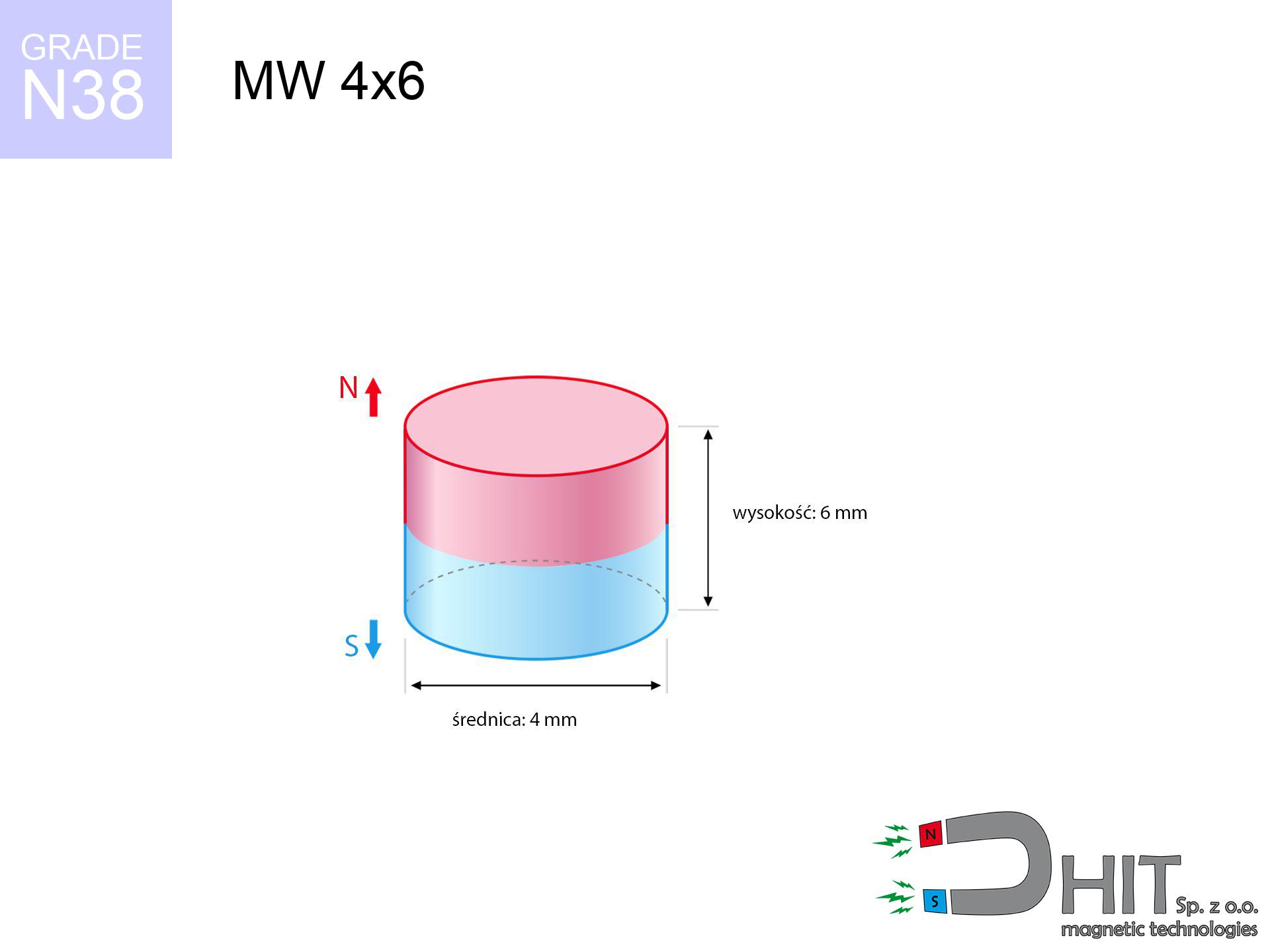
MW 4x6 / N38 - cylindrical magnet
cylindrical magnet
Catalog no 010078
GTIN/EAN: 5906301810773
Diameter Ø
4 mm [±0,1 mm]
Height
6 mm [±0,1 mm]
Weight
0.57 g
Magnetization Direction
↑ axial
Load capacity
0.41 kg / 4.06 N
Magnetic Induction
586.32 mT / 5863 Gs
Coating
[NiCuNi] Nickel
0.381 ZŁ with VAT / pcs + price for transport
0.310 ZŁ net + 23% VAT / pcs
bulk discounts:
Need more?Engineering report for this magnet
Full PDF analysis: pull and shear force, effect of distance, temperature and plate thickness, safety distances and the demagnetization curve.
Call us now
+48 22 499 98 98
if you prefer contact us through
form
through our site.
Parameters and appearance of neodymium magnets can be checked with our
power calculator.
Same-day processing for orders placed before 14:00.
Technical - MW 4x6 / N38 - cylindrical magnet
Specification / characteristics - MW 4x6 / N38 - cylindrical magnet
| properties | values |
|---|---|
| Cat. no. | 010078 |
| GTIN/EAN | 5906301810773 |
| Production/Distribution | Dhit sp. z o.o. |
| Country of origin | Poland / China / Germany |
| Customs code | 85059029 |
| Diameter Ø | 4 mm [±0,1 mm] |
| Height | 6 mm [±0,1 mm] |
| Weight | 0.57 g |
| Magnetization Direction | ↑ axial |
| Load capacity ~ ? | 0.41 kg / 4.06 N |
| Magnetic Induction ~ ? | 586.32 mT / 5863 Gs |
| Coating | [NiCuNi] Nickel |
| Manufacturing Tolerance | ±0.1 mm |
Magnetic properties of material N38
| properties | values | units |
|---|---|---|
| remenance Br [min. - max.] ? | 12.2-12.6 | kGs |
| remenance Br [min. - max.] ? | 1220-1260 | mT |
| coercivity bHc ? | 10.8-11.5 | kOe |
| coercivity bHc ? | 860-915 | kA/m |
| actual internal force iHc | ≥ 12 | kOe |
| actual internal force iHc | ≥ 955 | kA/m |
| energy density [min. - max.] ? | 36-38 | BH max MGOe |
| energy density [min. - max.] ? | 287-303 | BH max KJ/m |
| max. temperature ? | ≤ 80 | °C |
Physical properties of sintered neodymium magnets Nd2Fe14B at 20°C
| properties | values | units |
|---|---|---|
| Vickers hardness | ≥550 | Hv |
| Density | ≥7.4 | g/cm3 |
| Curie Temperature TC | 312 - 380 | °C |
| Curie Temperature TF | 593 - 716 | °F |
| Specific resistance | 150 | μΩ⋅cm |
| Bending strength | 250 | MPa |
| Compressive strength | 1000~1100 | MPa |
| Thermal expansion parallel (∥) to orientation (M) | (3-4) x 10-6 | °C-1 |
| Thermal expansion perpendicular (⊥) to orientation (M) | -(1-3) x 10-6 | °C-1 |
| Young's modulus | 1.7 x 10⁴ | kg/mm² |
Technical simulation of the product - data
Presented values constitute the outcome of a physical analysis. Values are based on models for the material Nd2Fe14B. Real-world parameters may differ from theoretical values. Use these calculations as a supplementary guide during assembly planning.
Table 1: Static pull force (pull vs distance) - power drop
MW 4x6 / N38
| Distance (mm) | Induction (Gauss) / mT | Pull Force (kg/lbs/g/N) | Risk Status |
|---|---|---|---|
| 0 mm |
5852 Gs
585.2 mT
|
0.41 kg / 0.90 lbs
410.0 g / 4.0 N
|
safe |
| 1 mm |
3189 Gs
318.9 mT
|
0.12 kg / 0.27 lbs
121.7 g / 1.2 N
|
safe |
| 2 mm |
1631 Gs
163.1 mT
|
0.03 kg / 0.07 lbs
31.8 g / 0.3 N
|
safe |
| 3 mm |
894 Gs
89.4 mT
|
0.01 kg / 0.02 lbs
9.6 g / 0.1 N
|
safe |
| 5 mm |
343 Gs
34.3 mT
|
0.00 kg / 0.00 lbs
1.4 g / 0.0 N
|
safe |
| 10 mm |
73 Gs
7.3 mT
|
0.00 kg / 0.00 lbs
0.1 g / 0.0 N
|
safe |
| 15 mm |
26 Gs
2.6 mT
|
0.00 kg / 0.00 lbs
0.0 g / 0.0 N
|
safe |
| 20 mm |
13 Gs
1.3 mT
|
0.00 kg / 0.00 lbs
0.0 g / 0.0 N
|
safe |
| 30 mm |
4 Gs
0.4 mT
|
0.00 kg / 0.00 lbs
0.0 g / 0.0 N
|
safe |
| 50 mm |
1 Gs
0.1 mT
|
0.00 kg / 0.00 lbs
0.0 g / 0.0 N
|
safe |
Table 2: Vertical capacity (vertical surface)
MW 4x6 / N38
| Distance (mm) | Friction coefficient | Pull Force (kg/lbs/g/N) |
|---|---|---|
| 0 mm | Stal (~0.2) |
0.08 kg / 0.18 lbs
82.0 g / 0.8 N
|
| 1 mm | Stal (~0.2) |
0.02 kg / 0.05 lbs
24.0 g / 0.2 N
|
| 2 mm | Stal (~0.2) |
0.01 kg / 0.01 lbs
6.0 g / 0.1 N
|
| 3 mm | Stal (~0.2) |
0.00 kg / 0.00 lbs
2.0 g / 0.0 N
|
| 5 mm | Stal (~0.2) |
0.00 kg / 0.00 lbs
0.0 g / 0.0 N
|
| 10 mm | Stal (~0.2) |
0.00 kg / 0.00 lbs
0.0 g / 0.0 N
|
| 15 mm | Stal (~0.2) |
0.00 kg / 0.00 lbs
0.0 g / 0.0 N
|
| 20 mm | Stal (~0.2) |
0.00 kg / 0.00 lbs
0.0 g / 0.0 N
|
| 30 mm | Stal (~0.2) |
0.00 kg / 0.00 lbs
0.0 g / 0.0 N
|
| 50 mm | Stal (~0.2) |
0.00 kg / 0.00 lbs
0.0 g / 0.0 N
|
Table 3: Wall mounting (sliding) - vertical pull
MW 4x6 / N38
| Surface type | Friction coefficient / % Mocy | Max load (kg/lbs/g/N) |
|---|---|---|
| Raw steel |
µ = 0.3
30% Nominalnej Siły
|
0.12 kg / 0.27 lbs
123.0 g / 1.2 N
|
| Painted steel (standard) |
µ = 0.2
20% Nominalnej Siły
|
0.08 kg / 0.18 lbs
82.0 g / 0.8 N
|
| Oily/slippery steel |
µ = 0.1
10% Nominalnej Siły
|
0.04 kg / 0.09 lbs
41.0 g / 0.4 N
|
| Magnet with anti-slip rubber |
µ = 0.5
50% Nominalnej Siły
|
0.21 kg / 0.45 lbs
205.0 g / 2.0 N
|
Table 4: Steel thickness (substrate influence) - sheet metal selection
MW 4x6 / N38
| Steel thickness (mm) | % power | Real pull force (kg/lbs/g/N) |
|---|---|---|
| 0.5 mm |
|
0.04 kg / 0.09 lbs
41.0 g / 0.4 N
|
| 1 mm |
|
0.10 kg / 0.23 lbs
102.5 g / 1.0 N
|
| 2 mm |
|
0.21 kg / 0.45 lbs
205.0 g / 2.0 N
|
| 3 mm |
|
0.31 kg / 0.68 lbs
307.5 g / 3.0 N
|
| 5 mm |
|
0.41 kg / 0.90 lbs
410.0 g / 4.0 N
|
| 10 mm |
|
0.41 kg / 0.90 lbs
410.0 g / 4.0 N
|
| 11 mm |
|
0.41 kg / 0.90 lbs
410.0 g / 4.0 N
|
| 12 mm |
|
0.41 kg / 0.90 lbs
410.0 g / 4.0 N
|
Table 5: Working in heat (stability) - power drop
MW 4x6 / N38
| Ambient temp. (°C) | Power loss | Remaining pull (kg/lbs/g/N) | Status |
|---|---|---|---|
| 20 °C | 0.0% |
0.41 kg / 0.90 lbs
410.0 g / 4.0 N
|
OK |
| 40 °C | -2.2% |
0.40 kg / 0.88 lbs
401.0 g / 3.9 N
|
OK |
| 60 °C | -4.4% |
0.39 kg / 0.86 lbs
392.0 g / 3.8 N
|
OK |
| 80 °C | -6.6% |
0.38 kg / 0.84 lbs
382.9 g / 3.8 N
|
|
| 100 °C | -28.8% |
0.29 kg / 0.64 lbs
291.9 g / 2.9 N
|
Table 6: Two magnets (repulsion) - field collision
MW 4x6 / N38
| Gap (mm) | Attraction (kg/lbs) (N-S) | Shear Strength (kg/lbs/g/N) | Repulsion (kg/lbs) (N-N) |
|---|---|---|---|
| 0 mm |
2.65 kg / 5.85 lbs
6 085 Gs
|
0.40 kg / 0.88 lbs
398 g / 3.9 N
|
N/A |
| 1 mm |
1.51 kg / 3.34 lbs
8 844 Gs
|
0.23 kg / 0.50 lbs
227 g / 2.2 N
|
1.36 kg / 3.01 lbs
~0 Gs
|
| 2 mm |
0.79 kg / 1.74 lbs
6 377 Gs
|
0.12 kg / 0.26 lbs
118 g / 1.2 N
|
0.71 kg / 1.56 lbs
~0 Gs
|
| 3 mm |
0.40 kg / 0.88 lbs
4 541 Gs
|
0.06 kg / 0.13 lbs
60 g / 0.6 N
|
0.36 kg / 0.79 lbs
~0 Gs
|
| 5 mm |
0.11 kg / 0.24 lbs
2 388 Gs
|
0.02 kg / 0.04 lbs
17 g / 0.2 N
|
0.10 kg / 0.22 lbs
~0 Gs
|
| 10 mm |
0.01 kg / 0.02 lbs
687 Gs
|
0.00 kg / 0.00 lbs
1 g / 0.0 N
|
0.00 kg / 0.00 lbs
~0 Gs
|
| 20 mm |
0.00 kg / 0.00 lbs
145 Gs
|
0.00 kg / 0.00 lbs
0 g / 0.0 N
|
0.00 kg / 0.00 lbs
~0 Gs
|
| 50 mm |
0.00 kg / 0.00 lbs
14 Gs
|
0.00 kg / 0.00 lbs
0 g / 0.0 N
|
0.00 kg / 0.00 lbs
~0 Gs
|
| 60 mm |
0.00 kg / 0.00 lbs
8 Gs
|
0.00 kg / 0.00 lbs
0 g / 0.0 N
|
0.00 kg / 0.00 lbs
~0 Gs
|
| 70 mm |
0.00 kg / 0.00 lbs
5 Gs
|
0.00 kg / 0.00 lbs
0 g / 0.0 N
|
0.00 kg / 0.00 lbs
~0 Gs
|
| 80 mm |
0.00 kg / 0.00 lbs
4 Gs
|
0.00 kg / 0.00 lbs
0 g / 0.0 N
|
0.00 kg / 0.00 lbs
~0 Gs
|
| 90 mm |
0.00 kg / 0.00 lbs
3 Gs
|
0.00 kg / 0.00 lbs
0 g / 0.0 N
|
0.00 kg / 0.00 lbs
~0 Gs
|
| 100 mm |
0.00 kg / 0.00 lbs
2 Gs
|
0.00 kg / 0.00 lbs
0 g / 0.0 N
|
0.00 kg / 0.00 lbs
~0 Gs
|
Table 7: Protective zones (electronics) - warnings
MW 4x6 / N38
| Object / Device | Limit (Gauss) / mT | Safe distance |
|---|---|---|
| Pacemaker | 5 Gs (0.5 mT) | 3.0 cm |
| Hearing aid | 10 Gs (1.0 mT) | 2.5 cm |
| Mechanical watch | 20 Gs (2.0 mT) | 2.0 cm |
| Phone / Smartphone | 40 Gs (4.0 mT) | 1.5 cm |
| Remote | 50 Gs (5.0 mT) | 1.5 cm |
| Payment card | 400 Gs (40.0 mT) | 0.5 cm |
| HDD hard drive | 600 Gs (60.0 mT) | 0.5 cm |
Table 8: Dynamics (cracking risk) - collision effects
MW 4x6 / N38
| Start from (mm) | Speed (km/h) | Energy (J) | Predicted outcome |
|---|---|---|---|
| 10 mm |
27.05 km/h
(7.51 m/s)
|
0.02 J | |
| 30 mm |
46.85 km/h
(13.01 m/s)
|
0.05 J | |
| 50 mm |
60.48 km/h
(16.80 m/s)
|
0.08 J | |
| 100 mm |
85.53 km/h
(23.76 m/s)
|
0.16 J |
Table 9: Coating parameters (durability)
MW 4x6 / N38
| Technical parameter | Value / Description |
|---|---|
| Coating type | [NiCuNi] Nickel |
| Layer structure | Nickel - Copper - Nickel |
| Layer thickness | 10-20 µm |
| Salt spray test (SST) ? | 24 h |
| Recommended environment | Indoors only (dry) |
Table 10: Construction data (Pc)
MW 4x6 / N38
| Parameter | Value | SI Unit / Description |
|---|---|---|
| Magnetic Flux | 792 Mx | 7.9 µWb |
| Pc Coefficient | 1.09 | High (Stable) |
Table 11: Hydrostatics and buoyancy
MW 4x6 / N38
| Environment | Effective steel pull | Effect |
|---|---|---|
| Air (land) | 0.41 kg | Standard |
| Water (riverbed) |
0.47 kg
(+0.06 kg buoyancy gain)
|
+14.5% |
1. Shear force
*Warning: On a vertical surface, the magnet retains merely ~20% of its max power.
2. Steel thickness impact
*Thin steel (e.g. computer case) severely weakens the holding force.
3. Thermal stability
*For N38 grade, the critical limit is 80°C.
4. Demagnetization curve and operating point (B-H)
chart generated for the permeance coefficient Pc (Permeance Coefficient) = 1.09
This simulation demonstrates the magnetic stability of the selected magnet under specific geometric conditions. The solid red line represents the demagnetization curve (material potential), while the dashed blue line is the load line based on the magnet's geometry. The Pc (Permeance Coefficient), also known as the load line slope, is a dimensionless value that describes the relationship between the magnet's shape and its magnetic stability. The intersection of these two lines (the black dot) is the operating point — it determines the actual magnetic flux density generated by the magnet in this specific configuration. A higher Pc value means the magnet is more 'slender' (tall relative to its area), resulting in a higher operating point and better resistance to irreversible demagnetization caused by external fields or temperature. A value of 0.42 is relatively low (typical for flat magnets), meaning the operating point is closer to the 'knee' of the curve — caution is advised when operating at temperatures near the maximum limit to avoid strength loss.
Material specification
| iron (Fe) | 64% – 68% |
| neodymium (Nd) | 29% – 32% |
| boron (B) | 1.1% – 1.2% |
| dysprosium (Dy) | 0.5% – 2.0% |
| coating (Ni-Cu-Ni) | < 0.05% |
Ecology and recycling (GPSR)
| recyclability (EoL) | 100% |
| recycled raw materials | ~10% (pre-cons) |
| carbon footprint | low / zredukowany |
| waste code (EWC) | 16 02 16 |
See more offers
![UMGGZ 88x8.5 [M8] GZ / N38 - rubber magnetic holder external thread](https://cdn3.dhit.pl/graphics/products/umg-88x8.5-m8-gz-waf.jpg "UMGGZ 88x8.5 [M8] GZ / N38 - rubber magnetic holder external thread")


![HH 20x7.2 [M4] / N38 - through hole magnetic holder](https://cdn3.dhit.pl/graphics/products/hh-20x7.2-m4-luc.jpg "HH 20x7.2 [M4] / N38 - through hole magnetic holder")
Pros and cons of rare earth magnets.
Strengths
- They virtually do not lose strength, because even after ten years the performance loss is only ~1% (based on calculations),
- Magnets perfectly protect themselves against loss of magnetization caused by ambient magnetic noise,
- In other words, due to the reflective surface of gold, the element becomes visually attractive,
- Magnets have extremely high magnetic induction on the outer side,
- Due to their durability and thermal resistance, neodymium magnets are capable of operate (depending on the shape) even at high temperatures reaching 230°C or more...
- Thanks to modularity in constructing and the capacity to customize to individual projects,
- Versatile presence in electronics industry – they serve a role in magnetic memories, motor assemblies, medical devices, also other advanced devices.
- Thanks to their power density, small magnets offer high operating force, occupying minimum space,
Weaknesses
- To avoid cracks upon strong impacts, we recommend using special steel holders. Such a solution secures the magnet and simultaneously increases its durability.
- We warn that neodymium magnets can lose their power at high temperatures. To prevent this, we advise our specialized [AH] magnets, which work effectively even at 230°C.
- They rust in a humid environment - during use outdoors we suggest using waterproof magnets e.g. in rubber, plastic
- We suggest cover - magnetic holder, due to difficulties in producing threads inside the magnet and complicated shapes.
- Possible danger related to microscopic parts of magnets can be dangerous, if swallowed, which gains importance in the context of child health protection. It is also worth noting that tiny parts of these products can complicate diagnosis medical in case of swallowing.
- Higher cost of purchase is a significant factor to consider compared to ceramic magnets, especially in budget applications
Lifting parameters
Breakaway strength of the magnet in ideal conditions – what contributes to it?
- on a block made of structural steel, optimally conducting the magnetic flux
- whose transverse dimension is min. 10 mm
- with a plane free of scratches
- under conditions of gap-free contact (metal-to-metal)
- under axial application of breakaway force (90-degree angle)
- in stable room temperature
What influences lifting capacity in practice
- Air gap (betwixt the magnet and the plate), because even a microscopic distance (e.g. 0.5 mm) results in a decrease in lifting capacity by up to 50% (this also applies to varnish, corrosion or debris).
- Loading method – declared lifting capacity refers to detachment vertically. When slipping, the magnet holds much less (typically approx. 20-30% of nominal force).
- Substrate thickness – for full efficiency, the steel must be sufficiently thick. Thin sheet limits the attraction force (the magnet "punches through" it).
- Plate material – mild steel gives the best results. Alloy steels lower magnetic permeability and holding force.
- Surface quality – the smoother and more polished the plate, the larger the contact zone and higher the lifting capacity. Unevenness creates an air distance.
- Temperature – temperature increase causes a temporary drop of force. It is worth remembering the thermal limit for a given model.
Lifting capacity testing was carried out on plates with a smooth surface of optimal thickness, under a perpendicular pulling force, whereas under parallel forces the lifting capacity is smaller. Moreover, even a slight gap between the magnet and the plate decreases the holding force.
Precautions when working with NdFeB magnets
Pacemakers
Patients with a ICD should keep an safe separation from magnets. The magnetism can stop the operation of the life-saving device.
Avoid contact if allergic
Warning for allergy sufferers: The nickel-copper-nickel coating contains nickel. If an allergic reaction occurs, immediately stop working with magnets and wear gloves.
Conscious usage
Exercise caution. Neodymium magnets attract from a long distance and connect with huge force, often quicker than you can move away.
Dust is flammable
Mechanical processing of neodymium magnets poses a fire hazard. Neodymium dust oxidizes rapidly with oxygen and is hard to extinguish.
Power loss in heat
Monitor thermal conditions. Exposing the magnet above 80 degrees Celsius will permanently weaken its magnetic structure and strength.
Swallowing risk
Adult use only. Small elements can be swallowed, leading to intestinal necrosis. Store away from kids and pets.
Magnetic media
Intense magnetic fields can erase data on payment cards, hard drives, and other magnetic media. Keep a distance of min. 10 cm.
Fragile material
Despite the nickel coating, the material is delicate and cannot withstand shocks. Do not hit, as the magnet may crumble into sharp, dangerous pieces.
Impact on smartphones
A powerful magnetic field disrupts the operation of magnetometers in smartphones and navigation systems. Maintain magnets near a smartphone to prevent damaging the sensors.
Crushing risk
Big blocks can crush fingers instantly. Never place your hand between two strong magnets.
Tabela kosztu i czasu dostawy
Płatność przed wysyłką:

GLS kurier
Przesyłka będzie u Ciebie za 2-3 dni
14.99 ZŁ

InPost Paczkomaty 24/7
Przesyłka będzie u Ciebie za 1-2 dni
12.30 ZŁ
Płatność przy odbiorze (pobranie):
GLS kurier
Przesyłka będzie u Ciebie za 1-2 dni
23.00 ZŁ
Rate the product
Your rating