

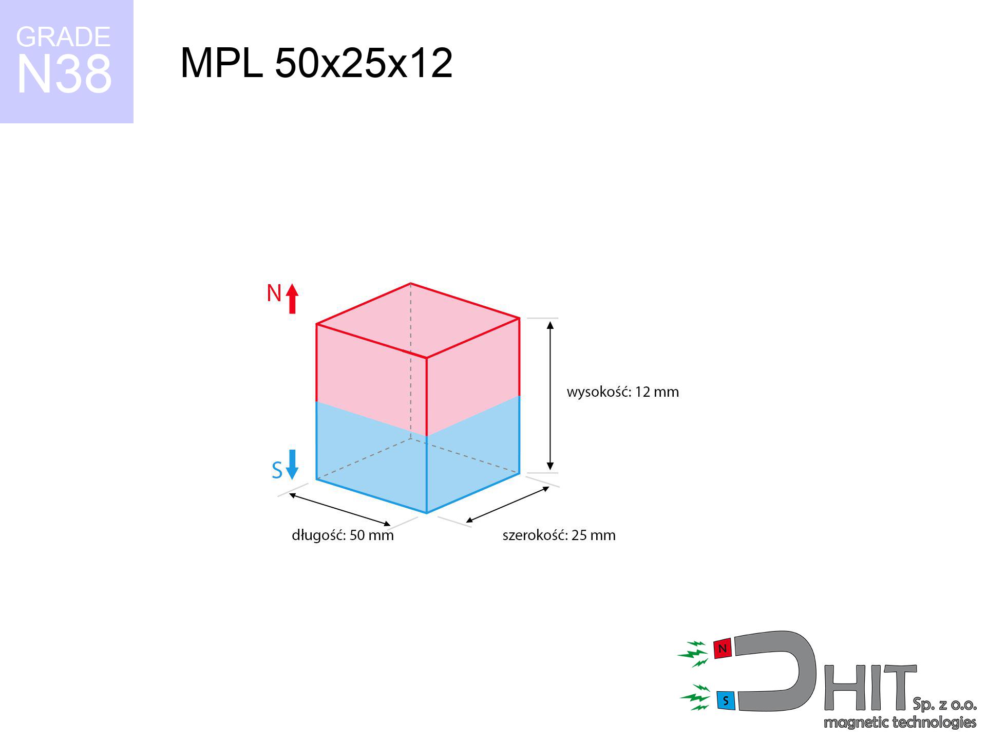
MPL 50x25x12 / N38 - lamellar magnet
lamellar magnet
Catalog no 020343
GTIN/EAN: 5906301811855
- length
- 50 mm [±0,1 mm]
- Width
- 25 mm [±0,1 mm]
- Height
- 12 mm [±0,1 mm]
- Weight
- 112.5 g
- Magnetization Direction
- ↑ axial
- Coating
- [NiCuNi] Nickel
45.51 zł with VAT / pcs + price for transport
37.00 zł net + 23% VAT / pcs
bulk discounts:
Need more?Engineering report for this magnet
Full PDF analysis: pull and shear force, effect of distance, temperature and plate thickness, safety distances and the demagnetization curve.
Pick up the phone and ask
+48 22 499 98 98
otherwise contact us using
request form
the contact page.
Force along with shape of a neodymium magnet can be analyzed using our
modular calculator.
Same-day shipping for orders placed before 14:00.
Technical - MPL 50x25x12 / N38 - lamellar magnet
Specification / characteristics - MPL 50x25x12 / N38 - lamellar magnet
| properties | values |
|---|---|
| Cat. no. | 020343 |
| GTIN/EAN | 5906301811855 |
| Production/Distribution | Dhit sp. z o.o. |
| Country of origin | Poland / China / Germany |
| Customs code | 85059029 |
| length | 50 mm [±0,1 mm] |
| Width | 25 mm [±0,1 mm] |
| Height | 12 mm [±0,1 mm] |
| Weight | 112.5 g |
| Magnetization Direction | ↑ axial |
| Load capacity ~ ? | 37.12 kg / 364.18 N |
| Magnetic Induction ~ ? | 340.43 mT / 3404 Gs |
| Coating | [NiCuNi] Nickel |
| Manufacturing Tolerance | ±0.1 mm |
Magnetic properties of material N38
| properties | values | units |
|---|---|---|
| remenance Br [min. - max.] ? | 12.2-12.6 | kGs |
| remenance Br [min. - max.] ? | 1220-1260 | mT |
| coercivity bHc ? | 10.8-11.5 | kOe |
| coercivity bHc ? | 860-915 | kA/m |
| actual internal force iHc | ≥ 12 | kOe |
| actual internal force iHc | ≥ 955 | kA/m |
| energy density [min. - max.] ? | 36-38 | BH max MGOe |
| energy density [min. - max.] ? | 287-303 | BH max KJ/m |
| max. temperature ? | ≤ 80 | °C |
Physical properties of sintered neodymium magnets Nd2Fe14B at 20°C
| properties | values | units |
|---|---|---|
| Vickers hardness | ≥550 | Hv |
| Density | ≥7.4 | g/cm3 |
| Curie Temperature TC | 312 - 380 | °C |
| Curie Temperature TF | 593 - 716 | °F |
| Specific resistance | 150 | μΩ⋅cm |
| Bending strength | 250 | MPa |
| Compressive strength | 1000~1100 | MPa |
| Thermal expansion parallel (∥) to orientation (M) | (3-4) x 10-6 | °C-1 |
| Thermal expansion perpendicular (⊥) to orientation (M) | -(1-3) x 10-6 | °C-1 |
| Young's modulus | 1.7 x 10⁴ | kg/mm² |
Technical modeling of the magnet - report
Presented values are the direct effect of a engineering analysis. Results were calculated on algorithms for the class Nd2Fe14B. Actual performance might slightly differ. Treat these data as a preliminary roadmap during assembly planning.
Table 1: Static force (force vs gap) - power drop
MPL 50x25x12 / N38
| Distance (mm) | Induction (Gauss) / mT | Pull Force (kg/lbs/g/N) | Risk Status |
|---|---|---|---|
| 0 mm |
3404 Gs
340.4 mT
|
37.12 kg / 81.84 LBS
37120.0 g / 364.1 N
|
crushing |
| 1 mm |
3234 Gs
323.4 mT
|
33.50 kg / 73.86 LBS
33501.5 g / 328.6 N
|
crushing |
| 2 mm |
3052 Gs
305.2 mT
|
29.85 kg / 65.80 LBS
29847.1 g / 292.8 N
|
crushing |
| 3 mm |
2866 Gs
286.6 mT
|
26.32 kg / 58.02 LBS
26317.3 g / 258.2 N
|
crushing |
| 5 mm |
2496 Gs
249.6 mT
|
19.97 kg / 44.02 LBS
19965.4 g / 195.9 N
|
crushing |
| 10 mm |
1702 Gs
170.2 mT
|
9.28 kg / 20.45 LBS
9278.2 g / 91.0 N
|
medium risk |
| 15 mm |
1151 Gs
115.1 mT
|
4.25 kg / 9.36 LBS
4246.0 g / 41.7 N
|
medium risk |
| 20 mm |
792 Gs
79.2 mT
|
2.01 kg / 4.44 LBS
2012.1 g / 19.7 N
|
medium risk |
| 30 mm |
404 Gs
40.4 mT
|
0.52 kg / 1.15 LBS
523.0 g / 5.1 N
|
weak grip |
| 50 mm |
137 Gs
13.7 mT
|
0.06 kg / 0.13 LBS
60.1 g / 0.6 N
|
weak grip |
Table 2: Slippage force (wall)
MPL 50x25x12 / N38
| Distance (mm) | Friction coefficient | Pull Force (kg/lbs/g/N) |
|---|---|---|
| 0 mm | Stal (~0.2) |
7.42 kg / 16.37 LBS
7424.0 g / 72.8 N
|
| 1 mm | Stal (~0.2) |
6.70 kg / 14.77 LBS
6700.0 g / 65.7 N
|
| 2 mm | Stal (~0.2) |
5.97 kg / 13.16 LBS
5970.0 g / 58.6 N
|
| 3 mm | Stal (~0.2) |
5.26 kg / 11.61 LBS
5264.0 g / 51.6 N
|
| 5 mm | Stal (~0.2) |
3.99 kg / 8.81 LBS
3994.0 g / 39.2 N
|
| 10 mm | Stal (~0.2) |
1.86 kg / 4.09 LBS
1856.0 g / 18.2 N
|
| 15 mm | Stal (~0.2) |
0.85 kg / 1.87 LBS
850.0 g / 8.3 N
|
| 20 mm | Stal (~0.2) |
0.40 kg / 0.89 LBS
402.0 g / 3.9 N
|
| 30 mm | Stal (~0.2) |
0.10 kg / 0.23 LBS
104.0 g / 1.0 N
|
| 50 mm | Stal (~0.2) |
0.01 kg / 0.03 LBS
12.0 g / 0.1 N
|
Table 3: Wall mounting (sliding) - behavior on slippery surfaces
MPL 50x25x12 / N38
| Surface type | Friction coefficient / % Mocy | Max load (kg/lbs/g/N) |
|---|---|---|
| Raw steel |
µ = 0.3
30% Nominalnej Siły
|
11.14 kg / 24.55 LBS
11136.0 g / 109.2 N
|
| Painted steel (standard) |
µ = 0.2
20% Nominalnej Siły
|
7.42 kg / 16.37 LBS
7424.0 g / 72.8 N
|
| Oily/slippery steel |
µ = 0.1
10% Nominalnej Siły
|
3.71 kg / 8.18 LBS
3712.0 g / 36.4 N
|
| Magnet with anti-slip rubber |
µ = 0.5
50% Nominalnej Siły
|
18.56 kg / 40.92 LBS
18560.0 g / 182.1 N
|
Table 4: Steel thickness (saturation) - sheet metal selection
MPL 50x25x12 / N38
| Steel thickness (mm) | % power | Real pull force (kg/lbs/g/N) |
|---|---|---|
| 0.5 mm |
|
1.86 kg / 4.09 LBS
1856.0 g / 18.2 N
|
| 1 mm |
|
4.64 kg / 10.23 LBS
4640.0 g / 45.5 N
|
| 2 mm |
|
9.28 kg / 20.46 LBS
9280.0 g / 91.0 N
|
| 3 mm |
|
13.92 kg / 30.69 LBS
13920.0 g / 136.6 N
|
| 5 mm |
|
23.20 kg / 51.15 LBS
23200.0 g / 227.6 N
|
| 10 mm |
|
37.12 kg / 81.84 LBS
37120.0 g / 364.1 N
|
| 11 mm |
|
37.12 kg / 81.84 LBS
37120.0 g / 364.1 N
|
| 12 mm |
|
37.12 kg / 81.84 LBS
37120.0 g / 364.1 N
|
Table 5: Thermal stability (material behavior) - power drop
MPL 50x25x12 / N38
| Ambient temp. (°C) | Power loss | Remaining pull (kg/lbs/g/N) | Status |
|---|---|---|---|
| 20 °C | 0.0% |
37.12 kg / 81.84 LBS
37120.0 g / 364.1 N
|
OK |
| 40 °C | -2.2% |
36.30 kg / 80.04 LBS
36303.4 g / 356.1 N
|
OK |
| 60 °C | -4.4% |
35.49 kg / 78.23 LBS
35486.7 g / 348.1 N
|
|
| 80 °C | -6.6% |
34.67 kg / 76.43 LBS
34670.1 g / 340.1 N
|
|
| 100 °C | -28.8% |
26.43 kg / 58.27 LBS
26429.4 g / 259.3 N
|
Table 6: Two magnets (attraction) - field collision
MPL 50x25x12 / N38
| Gap (mm) | Attraction (kg/lbs) (N-S) | Shear Force (kg/lbs/g/N) | Repulsion (kg/lbs) (N-N) |
|---|---|---|---|
| 0 mm |
89.28 kg / 196.82 LBS
4 856 Gs
|
13.39 kg / 29.52 LBS
13392 g / 131.4 N
|
N/A |
| 1 mm |
84.99 kg / 187.37 LBS
6 642 Gs
|
12.75 kg / 28.11 LBS
12749 g / 125.1 N
|
76.49 kg / 168.63 LBS
~0 Gs
|
| 2 mm |
80.57 kg / 177.64 LBS
6 467 Gs
|
12.09 kg / 26.65 LBS
12086 g / 118.6 N
|
72.52 kg / 159.87 LBS
~0 Gs
|
| 3 mm |
76.16 kg / 167.90 LBS
6 287 Gs
|
11.42 kg / 25.19 LBS
11424 g / 112.1 N
|
68.54 kg / 151.11 LBS
~0 Gs
|
| 5 mm |
67.49 kg / 148.78 LBS
5 919 Gs
|
10.12 kg / 22.32 LBS
10123 g / 99.3 N
|
60.74 kg / 133.91 LBS
~0 Gs
|
| 10 mm |
48.02 kg / 105.86 LBS
4 992 Gs
|
7.20 kg / 15.88 LBS
7203 g / 70.7 N
|
43.22 kg / 95.28 LBS
~0 Gs
|
| 20 mm |
22.32 kg / 49.20 LBS
3 403 Gs
|
3.35 kg / 7.38 LBS
3347 g / 32.8 N
|
20.08 kg / 44.28 LBS
~0 Gs
|
| 50 mm |
2.41 kg / 5.31 LBS
1 118 Gs
|
0.36 kg / 0.80 LBS
361 g / 3.5 N
|
2.17 kg / 4.78 LBS
~0 Gs
|
| 60 mm |
1.26 kg / 2.77 LBS
808 Gs
|
0.19 kg / 0.42 LBS
189 g / 1.9 N
|
1.13 kg / 2.50 LBS
~0 Gs
|
| 70 mm |
0.69 kg / 1.52 LBS
598 Gs
|
0.10 kg / 0.23 LBS
103 g / 1.0 N
|
0.62 kg / 1.37 LBS
~0 Gs
|
| 80 mm |
0.39 kg / 0.87 LBS
452 Gs
|
0.06 kg / 0.13 LBS
59 g / 0.6 N
|
0.35 kg / 0.78 LBS
~0 Gs
|
| 90 mm |
0.23 kg / 0.52 LBS
349 Gs
|
0.04 kg / 0.08 LBS
35 g / 0.3 N
|
0.21 kg / 0.47 LBS
~0 Gs
|
| 100 mm |
0.14 kg / 0.32 LBS
274 Gs
|
0.02 kg / 0.05 LBS
22 g / 0.2 N
|
0.13 kg / 0.29 LBS
~0 Gs
|
Table 7: Protective zones (implants) - warnings
MPL 50x25x12 / N38
| Object / Device | Limit (Gauss) / mT | Safe distance |
|---|---|---|
| Pacemaker | 5 Gs (0.5 mT) | 17.5 cm |
| Hearing aid | 10 Gs (1.0 mT) | 14.0 cm |
| Timepiece | 20 Gs (2.0 mT) | 11.0 cm |
| Phone / Smartphone | 40 Gs (4.0 mT) | 8.5 cm |
| Car key | 50 Gs (5.0 mT) | 8.0 cm |
| Payment card | 400 Gs (40.0 mT) | 3.5 cm |
| HDD hard drive | 600 Gs (60.0 mT) | 2.5 cm |
Table 8: Dynamics (cracking risk) - warning
MPL 50x25x12 / N38
| Start from (mm) | Speed (km/h) | Energy (J) | Predicted outcome |
|---|---|---|---|
| 10 mm |
21.86 km/h
(6.07 m/s)
|
2.07 J | |
| 30 mm |
24.67 km/h
(6.85 m/s)
|
2.64 J | |
| 50 mm |
24.85 km/h
(6.90 m/s)
|
2.68 J | |
| 100 mm |
24.89 km/h
(6.91 m/s)
|
2.69 J |
Table 9: Anti-corrosion coating durability
MPL 50x25x12 / N38
| Technical parameter | Value / Description |
|---|---|
| Coating type | [NiCuNi] Nickel |
| Layer structure | Nickel - Copper - Nickel |
| Layer thickness | 10-20 µm |
| Salt spray test (SST) ? | 24 h |
| Recommended environment | Indoors only (dry) |
Table 10: Construction data (Flux)
MPL 50x25x12 / N38
| Parameter | Value | SI Unit / Description |
|---|---|---|
| Magnetic Flux | 42 945 Mx | 429.5 µWb |
| Pc Coefficient | 0.40 | Low (Flat) |
Table 11: Underwater work (magnet fishing)
MPL 50x25x12 / N38
| Environment | Effective steel pull | Effect |
|---|---|---|
| Air (land) | 37.12 kg | Standard |
| Water (riverbed) |
42.50 kg
(+5.38 kg buoyancy gain)
|
+14.5% |
1. Vertical hold
*Caution: On a vertical wall, the magnet holds merely ~20% of its max power.
2. Steel saturation
*Thin steel (e.g. computer case) drastically limits the holding force.
3. Power loss vs temp
*For standard magnets, the max working temp is 80°C.
4. Demagnetization curve and operating point (B-H)
chart generated for the permeance coefficient Pc (Permeance Coefficient) = 0.40
This simulation demonstrates the magnetic stability of the selected magnet under specific geometric conditions. The solid red line represents the demagnetization curve (material potential), while the dashed blue line is the load line based on the magnet's geometry. The Pc (Permeance Coefficient), also known as the load line slope, is a dimensionless value that describes the relationship between the magnet's shape and its magnetic stability. The intersection of these two lines (the black dot) is the operating point — it determines the actual magnetic flux density generated by the magnet in this specific configuration. A higher Pc value means the magnet is more 'slender' (tall relative to its area), resulting in a higher operating point and better resistance to irreversible demagnetization caused by external fields or temperature. A value of 0.42 is relatively low (typical for flat magnets), meaning the operating point is closer to the 'knee' of the curve — caution is advised when operating at temperatures near the maximum limit to avoid strength loss.
Chemical composition
| iron (Fe) | 64% – 68% |
| neodymium (Nd) | 29% – 32% |
| boron (B) | 1.1% – 1.2% |
| dysprosium (Dy) | 0.5% – 2.0% |
| coating (Ni-Cu-Ni) | < 0.05% |
Ecology and recycling (GPSR)
| recyclability (EoL) | 100% |
| recycled raw materials | ~10% (pre-cons) |
| carbon footprint | low / zredukowany |
| waste code (EWC) | 16 02 16 |
Other offers


![SM 25x350 [2xM8] / N42 - magnetic separator](https://cdn3.dhit.pl/graphics/products/sm-25x350-2xm8-pim.jpg "SM 25x350 [2xM8] / N42 - magnetic separator")

Pros as well as cons of neodymium magnets.
Benefits
- They virtually do not lose strength, because even after 10 years the performance loss is only ~1% (in laboratory conditions),
- Neodymium magnets are characterized by extremely resistant to demagnetization caused by external field sources,
- By using a shiny layer of nickel, the element has an professional look,
- Neodymium magnets ensure maximum magnetic induction on a contact point, which ensures high operational effectiveness,
- Made from properly selected components, these magnets show impressive resistance to high heat, enabling them to function (depending on their shape) at temperatures up to 230°C and above...
- Thanks to versatility in constructing and the capacity to modify to client solutions,
- Significant place in electronics industry – they are utilized in hard drives, motor assemblies, medical equipment, as well as technologically advanced constructions.
- Compactness – despite small sizes they provide effective action, making them ideal for precision applications
Weaknesses
- At very strong impacts they can break, therefore we advise placing them in strong housings. A metal housing provides additional protection against damage, as well as increases the magnet's durability.
- We warn that neodymium magnets can lose their strength at high temperatures. To prevent this, we recommend our specialized [AH] magnets, which work effectively even at 230°C.
- When exposed to humidity, magnets usually rust. To use them in conditions outside, it is recommended to use protective magnets, such as magnets in rubber or plastics, which prevent oxidation and corrosion.
- Limited possibility of creating nuts in the magnet and complicated forms - recommended is a housing - mounting mechanism.
- Health risk to health – tiny shards of magnets can be dangerous, when accidentally swallowed, which becomes key in the context of child health protection. Additionally, tiny parts of these devices are able to complicate diagnosis medical when they are in the body.
- Due to complex production process, their price is higher than average,
Pull force analysis
Maximum lifting force for a neodymium magnet – what contributes to it?
- with the use of a sheet made of special test steel, ensuring maximum field concentration
- whose thickness equals approx. 10 mm
- with an ground contact surface
- without any air gap between the magnet and steel
- under perpendicular force direction (90-degree angle)
- at temperature room level
Practical lifting capacity: influencing factors
- Air gap (between the magnet and the plate), since even a microscopic clearance (e.g. 0.5 mm) leads to a decrease in lifting capacity by up to 50% (this also applies to paint, corrosion or dirt).
- Angle of force application – maximum parameter is reached only during perpendicular pulling. The force required to slide of the magnet along the surface is typically many times smaller (approx. 1/5 of the lifting capacity).
- Wall thickness – thin material does not allow full use of the magnet. Part of the magnetic field passes through the material instead of generating force.
- Plate material – mild steel attracts best. Higher carbon content reduce magnetic permeability and holding force.
- Surface quality – the more even the plate, the better the adhesion and higher the lifting capacity. Roughness creates an air distance.
- Operating temperature – neodymium magnets have a sensitivity to temperature. When it is hot they lose power, and in frost gain strength (up to a certain limit).
Lifting capacity was assessed by applying a polished steel plate of suitable thickness (min. 20 mm), under perpendicular pulling force, whereas under attempts to slide the magnet the lifting capacity is smaller. In addition, even a minimal clearance between the magnet and the plate lowers the load capacity.
H&S for magnets
Threat to electronics
Powerful magnetic fields can erase data on payment cards, HDDs, and other magnetic media. Stay away of min. 10 cm.
Phone sensors
Navigation devices and mobile phones are highly susceptible to magnetism. Close proximity with a strong magnet can decalibrate the sensors in your phone.
Avoid contact if allergic
Certain individuals experience a hypersensitivity to Ni, which is the common plating for NdFeB magnets. Prolonged contact might lead to an allergic reaction. It is best to wear protective gloves.
Immense force
Before starting, check safety instructions. Sudden snapping can break the magnet or hurt your hand. Think ahead.
Thermal limits
Watch the temperature. Heating the magnet above 80 degrees Celsius will permanently weaken its properties and pulling force.
Health Danger
Medical warning: Neodymium magnets can turn off heart devices and defibrillators. Stay away if you have electronic implants.
Crushing force
Big blocks can smash fingers in a fraction of a second. Under no circumstances place your hand betwixt two strong magnets.
Beware of splinters
Despite metallic appearance, neodymium is brittle and not impact-resistant. Avoid impacts, as the magnet may shatter into hazardous fragments.
Do not give to children
Product intended for adults. Small elements pose a choking risk, causing serious injuries. Keep out of reach of kids and pets.
Fire warning
Mechanical processing of neodymium magnets poses a fire risk. Neodymium dust oxidizes rapidly with oxygen and is difficult to extinguish.
Tabela kosztu i czasu dostawy
Płatność przed wysyłką:

GLS kurier
Przesyłka będzie u Ciebie za 2-3 dni
14.99 ZŁ

InPost Paczkomaty 24/7
Przesyłka będzie u Ciebie za 1-2 dni
12.30 ZŁ
Płatność przy odbiorze (pobranie):
GLS kurier
Przesyłka będzie u Ciebie za 1-2 dni
23.00 ZŁ
Rate the product
Your rating