
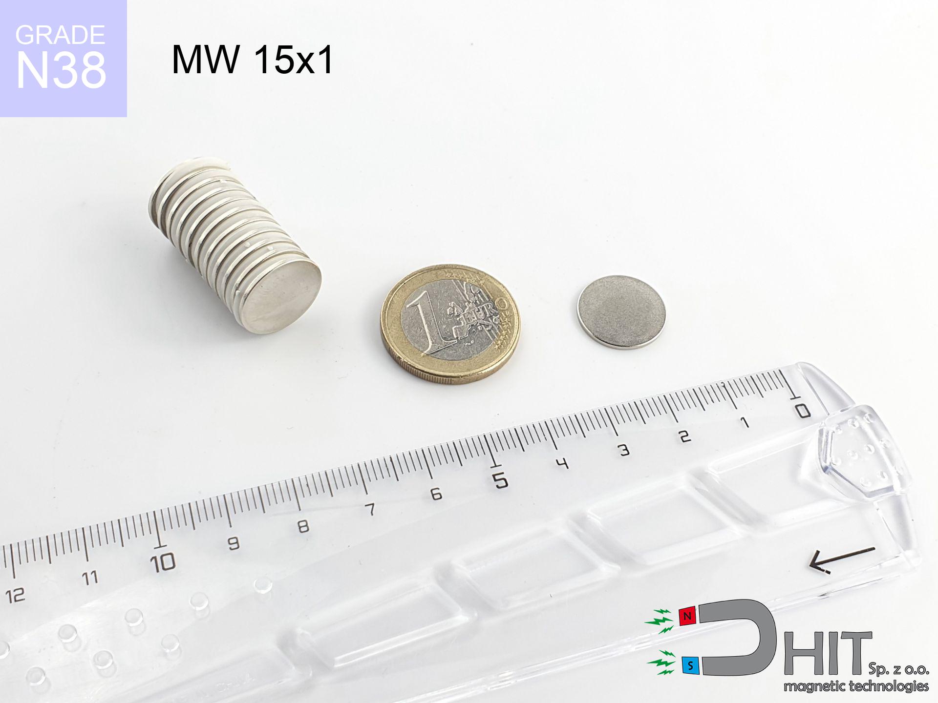
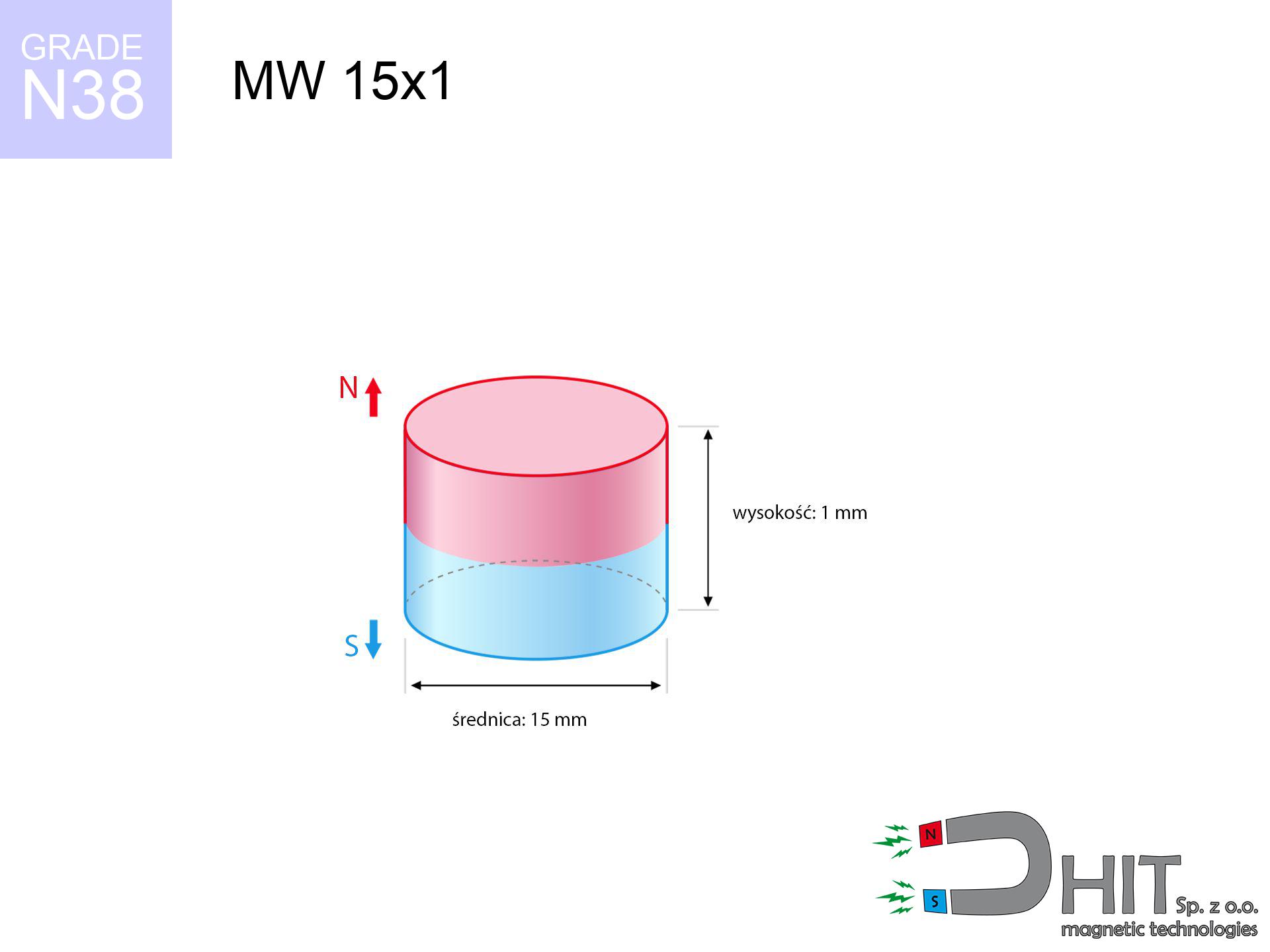
MW 15x1 / N38 - cylindrical magnet
cylindrical magnet
Catalog no 010026
GTIN/EAN: 5906301810254
Diameter Ø
15 mm [±0,1 mm]
Height
1 mm [±0,1 mm]
Weight
1.33 g
Magnetization Direction
↑ axial
Load capacity
0.44 kg / 4.29 N
Magnetic Induction
81.93 mT / 819 Gs
Coating
[NiCuNi] Nickel
0.800 ZŁ with VAT / pcs + price for transport
0.650 ZŁ net + 23% VAT / pcs
bulk discounts:
Need more?
Contact us by phone
+48 888 99 98 98
if you prefer send us a note through
request form
the contact form page.
Lifting power along with appearance of neodymium magnets can be reviewed with our
our magnetic calculator.
Same-day processing for orders placed before 14:00.
Technical details - MW 15x1 / N38 - cylindrical magnet
Specification / characteristics - MW 15x1 / N38 - cylindrical magnet
| properties | values |
|---|---|
| Cat. no. | 010026 |
| GTIN/EAN | 5906301810254 |
| Production/Distribution | Dhit sp. z o.o. |
| Country of origin | Poland / China / Germany |
| Customs code | 85059029 |
| Diameter Ø | 15 mm [±0,1 mm] |
| Height | 1 mm [±0,1 mm] |
| Weight | 1.33 g |
| Magnetization Direction | ↑ axial |
| Load capacity ~ ? | 0.44 kg / 4.29 N |
| Magnetic Induction ~ ? | 81.93 mT / 819 Gs |
| Coating | [NiCuNi] Nickel |
| Manufacturing Tolerance | ±0.1 mm |
Magnetic properties of material N38
| properties | values | units |
|---|---|---|
| remenance Br [min. - max.] ? | 12.2-12.6 | kGs |
| remenance Br [min. - max.] ? | 1220-1260 | mT |
| coercivity bHc ? | 10.8-11.5 | kOe |
| coercivity bHc ? | 860-915 | kA/m |
| actual internal force iHc | ≥ 12 | kOe |
| actual internal force iHc | ≥ 955 | kA/m |
| energy density [min. - max.] ? | 36-38 | BH max MGOe |
| energy density [min. - max.] ? | 287-303 | BH max KJ/m |
| max. temperature ? | ≤ 80 | °C |
Physical properties of sintered neodymium magnets Nd2Fe14B at 20°C
| properties | values | units |
|---|---|---|
| Vickers hardness | ≥550 | Hv |
| Density | ≥7.4 | g/cm3 |
| Curie Temperature TC | 312 - 380 | °C |
| Curie Temperature TF | 593 - 716 | °F |
| Specific resistance | 150 | μΩ⋅cm |
| Bending strength | 250 | MPa |
| Compressive strength | 1000~1100 | MPa |
| Thermal expansion parallel (∥) to orientation (M) | (3-4) x 10-6 | °C-1 |
| Thermal expansion perpendicular (⊥) to orientation (M) | -(1-3) x 10-6 | °C-1 |
| Young's modulus | 1.7 x 10⁴ | kg/mm² |
Technical analysis of the magnet - data
Presented values are the outcome of a engineering calculation. Results rely on models for the material Nd2Fe14B. Operational parameters may differ. Treat these calculations as a supplementary guide for designers.
Table 1: Static pull force (pull vs gap) - interaction chart
MW 15x1 / N38
| Distance (mm) | Induction (Gauss) / mT | Pull Force (kg/lbs/g/N) | Risk Status |
|---|---|---|---|
| 0 mm |
819 Gs
81.9 mT
|
0.44 kg / 0.97 LBS
440.0 g / 4.3 N
|
weak grip |
| 1 mm |
778 Gs
77.8 mT
|
0.40 kg / 0.88 LBS
397.0 g / 3.9 N
|
weak grip |
| 2 mm |
705 Gs
70.5 mT
|
0.33 kg / 0.72 LBS
326.0 g / 3.2 N
|
weak grip |
| 3 mm |
615 Gs
61.5 mT
|
0.25 kg / 0.55 LBS
248.0 g / 2.4 N
|
weak grip |
| 5 mm |
434 Gs
43.4 mT
|
0.12 kg / 0.27 LBS
123.5 g / 1.2 N
|
weak grip |
| 10 mm |
163 Gs
16.3 mT
|
0.02 kg / 0.04 LBS
17.3 g / 0.2 N
|
weak grip |
| 15 mm |
68 Gs
6.8 mT
|
0.00 kg / 0.01 LBS
3.1 g / 0.0 N
|
weak grip |
| 20 mm |
34 Gs
3.4 mT
|
0.00 kg / 0.00 LBS
0.7 g / 0.0 N
|
weak grip |
| 30 mm |
11 Gs
1.1 mT
|
0.00 kg / 0.00 LBS
0.1 g / 0.0 N
|
weak grip |
| 50 mm |
3 Gs
0.3 mT
|
0.00 kg / 0.00 LBS
0.0 g / 0.0 N
|
weak grip |
Table 2: Shear capacity (vertical surface)
MW 15x1 / N38
| Distance (mm) | Friction coefficient | Pull Force (kg/lbs/g/N) |
|---|---|---|
| 0 mm | Stal (~0.2) |
0.09 kg / 0.19 LBS
88.0 g / 0.9 N
|
| 1 mm | Stal (~0.2) |
0.08 kg / 0.18 LBS
80.0 g / 0.8 N
|
| 2 mm | Stal (~0.2) |
0.07 kg / 0.15 LBS
66.0 g / 0.6 N
|
| 3 mm | Stal (~0.2) |
0.05 kg / 0.11 LBS
50.0 g / 0.5 N
|
| 5 mm | Stal (~0.2) |
0.02 kg / 0.05 LBS
24.0 g / 0.2 N
|
| 10 mm | Stal (~0.2) |
0.00 kg / 0.01 LBS
4.0 g / 0.0 N
|
| 15 mm | Stal (~0.2) |
0.00 kg / 0.00 LBS
0.0 g / 0.0 N
|
| 20 mm | Stal (~0.2) |
0.00 kg / 0.00 LBS
0.0 g / 0.0 N
|
| 30 mm | Stal (~0.2) |
0.00 kg / 0.00 LBS
0.0 g / 0.0 N
|
| 50 mm | Stal (~0.2) |
0.00 kg / 0.00 LBS
0.0 g / 0.0 N
|
Table 3: Vertical assembly (sliding) - behavior on slippery surfaces
MW 15x1 / N38
| Surface type | Friction coefficient / % Mocy | Max load (kg/lbs/g/N) |
|---|---|---|
| Raw steel |
µ = 0.3
30% Nominalnej Siły
|
0.13 kg / 0.29 LBS
132.0 g / 1.3 N
|
| Painted steel (standard) |
µ = 0.2
20% Nominalnej Siły
|
0.09 kg / 0.19 LBS
88.0 g / 0.9 N
|
| Oily/slippery steel |
µ = 0.1
10% Nominalnej Siły
|
0.04 kg / 0.10 LBS
44.0 g / 0.4 N
|
| Magnet with anti-slip rubber |
µ = 0.5
50% Nominalnej Siły
|
0.22 kg / 0.49 LBS
220.0 g / 2.2 N
|
Table 4: Material efficiency (substrate influence) - sheet metal selection
MW 15x1 / N38
| Steel thickness (mm) | % power | Real pull force (kg/lbs/g/N) |
|---|---|---|
| 0.5 mm |
|
0.04 kg / 0.10 LBS
44.0 g / 0.4 N
|
| 1 mm |
|
0.11 kg / 0.24 LBS
110.0 g / 1.1 N
|
| 2 mm |
|
0.22 kg / 0.49 LBS
220.0 g / 2.2 N
|
| 3 mm |
|
0.33 kg / 0.73 LBS
330.0 g / 3.2 N
|
| 5 mm |
|
0.44 kg / 0.97 LBS
440.0 g / 4.3 N
|
| 10 mm |
|
0.44 kg / 0.97 LBS
440.0 g / 4.3 N
|
| 11 mm |
|
0.44 kg / 0.97 LBS
440.0 g / 4.3 N
|
| 12 mm |
|
0.44 kg / 0.97 LBS
440.0 g / 4.3 N
|
Table 5: Thermal stability (stability) - resistance threshold
MW 15x1 / N38
| Ambient temp. (°C) | Power loss | Remaining pull (kg/lbs/g/N) | Status |
|---|---|---|---|
| 20 °C | 0.0% |
0.44 kg / 0.97 LBS
440.0 g / 4.3 N
|
OK |
| 40 °C | -2.2% |
0.43 kg / 0.95 LBS
430.3 g / 4.2 N
|
OK |
| 60 °C | -4.4% |
0.42 kg / 0.93 LBS
420.6 g / 4.1 N
|
|
| 80 °C | -6.6% |
0.41 kg / 0.91 LBS
411.0 g / 4.0 N
|
|
| 100 °C | -28.8% |
0.31 kg / 0.69 LBS
313.3 g / 3.1 N
|
Table 6: Magnet-Magnet interaction (attraction) - field range
MW 15x1 / N38
| Gap (mm) | Attraction (kg/lbs) (N-S) | Sliding Force (kg/lbs/g/N) | Repulsion (kg/lbs) (N-N) |
|---|---|---|---|
| 0 mm |
0.73 kg / 1.61 LBS
1 597 Gs
|
0.11 kg / 0.24 LBS
110 g / 1.1 N
|
N/A |
| 1 mm |
0.70 kg / 1.55 LBS
1 607 Gs
|
0.11 kg / 0.23 LBS
106 g / 1.0 N
|
0.63 kg / 1.40 LBS
~0 Gs
|
| 2 mm |
0.66 kg / 1.45 LBS
1 556 Gs
|
0.10 kg / 0.22 LBS
99 g / 1.0 N
|
0.59 kg / 1.31 LBS
~0 Gs
|
| 3 mm |
0.60 kg / 1.33 LBS
1 489 Gs
|
0.09 kg / 0.20 LBS
91 g / 0.9 N
|
0.54 kg / 1.20 LBS
~0 Gs
|
| 5 mm |
0.48 kg / 1.05 LBS
1 323 Gs
|
0.07 kg / 0.16 LBS
71 g / 0.7 N
|
0.43 kg / 0.95 LBS
~0 Gs
|
| 10 mm |
0.21 kg / 0.45 LBS
868 Gs
|
0.03 kg / 0.07 LBS
31 g / 0.3 N
|
0.18 kg / 0.41 LBS
~0 Gs
|
| 20 mm |
0.03 kg / 0.06 LBS
325 Gs
|
0.00 kg / 0.01 LBS
4 g / 0.0 N
|
0.03 kg / 0.06 LBS
~0 Gs
|
| 50 mm |
0.00 kg / 0.00 LBS
37 Gs
|
0.00 kg / 0.00 LBS
0 g / 0.0 N
|
0.00 kg / 0.00 LBS
~0 Gs
|
| 60 mm |
0.00 kg / 0.00 LBS
23 Gs
|
0.00 kg / 0.00 LBS
0 g / 0.0 N
|
0.00 kg / 0.00 LBS
~0 Gs
|
| 70 mm |
0.00 kg / 0.00 LBS
15 Gs
|
0.00 kg / 0.00 LBS
0 g / 0.0 N
|
0.00 kg / 0.00 LBS
~0 Gs
|
| 80 mm |
0.00 kg / 0.00 LBS
10 Gs
|
0.00 kg / 0.00 LBS
0 g / 0.0 N
|
0.00 kg / 0.00 LBS
~0 Gs
|
| 90 mm |
0.00 kg / 0.00 LBS
7 Gs
|
0.00 kg / 0.00 LBS
0 g / 0.0 N
|
0.00 kg / 0.00 LBS
~0 Gs
|
| 100 mm |
0.00 kg / 0.00 LBS
5 Gs
|
0.00 kg / 0.00 LBS
0 g / 0.0 N
|
0.00 kg / 0.00 LBS
~0 Gs
|
Table 7: Protective zones (implants) - warnings
MW 15x1 / N38
| Object / Device | Limit (Gauss) / mT | Safe distance |
|---|---|---|
| Pacemaker | 5 Gs (0.5 mT) | 4.0 cm |
| Hearing aid | 10 Gs (1.0 mT) | 3.5 cm |
| Mechanical watch | 20 Gs (2.0 mT) | 2.5 cm |
| Phone / Smartphone | 40 Gs (4.0 mT) | 2.0 cm |
| Car key | 50 Gs (5.0 mT) | 2.0 cm |
| Payment card | 400 Gs (40.0 mT) | 1.0 cm |
| HDD hard drive | 600 Gs (60.0 mT) | 0.5 cm |
Table 8: Impact energy (cracking risk) - warning
MW 15x1 / N38
| Start from (mm) | Speed (km/h) | Energy (J) | Predicted outcome |
|---|---|---|---|
| 10 mm |
18.79 km/h
(5.22 m/s)
|
0.02 J | |
| 30 mm |
31.78 km/h
(8.83 m/s)
|
0.05 J | |
| 50 mm |
41.02 km/h
(11.39 m/s)
|
0.09 J | |
| 100 mm |
58.01 km/h
(16.11 m/s)
|
0.17 J |
Table 9: Anti-corrosion coating durability
MW 15x1 / N38
| Technical parameter | Value / Description |
|---|---|
| Coating type | [NiCuNi] Nickel |
| Layer structure | Nickel - Copper - Nickel |
| Layer thickness | 10-20 µm |
| Salt spray test (SST) ? | 24 h |
| Recommended environment | Indoors only (dry) |
Table 10: Electrical data (Flux)
MW 15x1 / N38
| Parameter | Value | SI Unit / Description |
|---|---|---|
| Magnetic Flux | 2 025 Mx | 20.3 µWb |
| Pc Coefficient | 0.11 | Low (Flat) |
Table 11: Physics of underwater searching
MW 15x1 / N38
| Environment | Effective steel pull | Effect |
|---|---|---|
| Air (land) | 0.44 kg | Standard |
| Water (riverbed) |
0.50 kg
(+0.06 kg buoyancy gain)
|
+14.5% |
1. Vertical hold
*Note: On a vertical surface, the magnet holds merely approx. 20-30% of its perpendicular strength.
2. Steel thickness impact
*Thin steel (e.g. 0.5mm PC case) significantly weakens the holding force.
3. Power loss vs temp
*For standard magnets, the max working temp is 80°C.
4. Demagnetization curve and operating point (B-H)
chart generated for the permeance coefficient Pc (Permeance Coefficient) = 0.11
This simulation demonstrates the magnetic stability of the selected magnet under specific geometric conditions. The solid red line represents the demagnetization curve (material potential), while the dashed blue line is the load line based on the magnet's geometry. The Pc (Permeance Coefficient), also known as the load line slope, is a dimensionless value that describes the relationship between the magnet's shape and its magnetic stability. The intersection of these two lines (the black dot) is the operating point — it determines the actual magnetic flux density generated by the magnet in this specific configuration. A higher Pc value means the magnet is more 'slender' (tall relative to its area), resulting in a higher operating point and better resistance to irreversible demagnetization caused by external fields or temperature. A value of 0.42 is relatively low (typical for flat magnets), meaning the operating point is closer to the 'knee' of the curve — caution is advised when operating at temperatures near the maximum limit to avoid strength loss.
Material specification
| iron (Fe) | 64% – 68% |
| neodymium (Nd) | 29% – 32% |
| boron (B) | 1.1% – 1.2% |
| dysprosium (Dy) | 0.5% – 2.0% |
| coating (Ni-Cu-Ni) | < 0.05% |
Environmental data
| recyclability (EoL) | 100% |
| recycled raw materials | ~10% (pre-cons) |
| carbon footprint | low / zredukowany |
| waste code (EWC) | 16 02 16 |
View also products
![SM 25x150 [2xM8] / N42 - magnetic separator](https://cdn3.dhit.pl/graphics/products/sm-25x150-2xm8-cim.jpg "SM 25x150 [2xM8] / N42 - magnetic separator")

![UMGZ 42x20x9 [M8] GZ / N38 - magnetic holder external thread](https://cdn3.dhit.pl/graphics/products/um-42x20x9-m8-gz-fof.jpg "UMGZ 42x20x9 [M8] GZ / N38 - magnetic holder external thread")

Advantages and disadvantages of neodymium magnets.
Pros
- They virtually do not lose power, because even after 10 years the performance loss is only ~1% (based on calculations),
- They maintain their magnetic properties even under strong external field,
- A magnet with a smooth silver surface has an effective appearance,
- Magnetic induction on the top side of the magnet remains extremely intense,
- Neodymium magnets are characterized by extremely high magnetic induction on the magnet surface and are able to act (depending on the shape) even at a temperature of 230°C or more...
- Considering the ability of free shaping and customization to custom requirements, NdFeB magnets can be produced in a wide range of shapes and sizes, which increases their versatility,
- Huge importance in modern technologies – they serve a role in mass storage devices, electric motors, precision medical tools, also complex engineering applications.
- Compactness – despite small sizes they provide effective action, making them ideal for precision applications
Weaknesses
- At strong impacts they can crack, therefore we advise placing them in special holders. A metal housing provides additional protection against damage and increases the magnet's durability.
- We warn that neodymium magnets can lose their strength at high temperatures. To prevent this, we suggest our specialized [AH] magnets, which work effectively even at 230°C.
- When exposed to humidity, magnets usually rust. To use them in conditions outside, it is recommended to use protective magnets, such as magnets in rubber or plastics, which prevent oxidation and corrosion.
- We suggest a housing - magnetic holder, due to difficulties in creating threads inside the magnet and complicated shapes.
- Health risk to health – tiny shards of magnets pose a threat, when accidentally swallowed, which is particularly important in the context of child health protection. Additionally, tiny parts of these devices can disrupt the diagnostic process medical when they are in the body.
- With large orders the cost of neodymium magnets is a challenge,
Lifting parameters
Best holding force of the magnet in ideal parameters – what contributes to it?
- using a plate made of low-carbon steel, acting as a circuit closing element
- possessing a massiveness of at least 10 mm to avoid saturation
- with a surface free of scratches
- under conditions of no distance (metal-to-metal)
- for force applied at a right angle (in the magnet axis)
- at conditions approx. 20°C
What influences lifting capacity in practice
- Distance – existence of foreign body (rust, tape, gap) interrupts the magnetic circuit, which reduces power rapidly (even by 50% at 0.5 mm).
- Direction of force – highest force is reached only during perpendicular pulling. The force required to slide of the magnet along the surface is standardly many times smaller (approx. 1/5 of the lifting capacity).
- Plate thickness – insufficiently thick sheet does not accept the full field, causing part of the flux to be wasted into the air.
- Chemical composition of the base – low-carbon steel attracts best. Higher carbon content lower magnetic properties and holding force.
- Base smoothness – the more even the plate, the better the adhesion and higher the lifting capacity. Roughness acts like micro-gaps.
- Thermal factor – hot environment weakens magnetic field. Exceeding the limit temperature can permanently demagnetize the magnet.
Lifting capacity testing was conducted on plates with a smooth surface of optimal thickness, under perpendicular forces, however under shearing force the load capacity is reduced by as much as 5 times. In addition, even a minimal clearance between the magnet and the plate reduces the lifting capacity.
H&S for magnets
Magnet fragility
NdFeB magnets are sintered ceramics, meaning they are fragile like glass. Clashing of two magnets leads to them breaking into shards.
Finger safety
Watch your fingers. Two large magnets will join immediately with a force of massive weight, crushing everything in their path. Be careful!
Medical implants
Patients with a heart stimulator must keep an safe separation from magnets. The magnetic field can stop the functioning of the life-saving device.
Combustion hazard
Mechanical processing of NdFeB material carries a risk of fire hazard. Neodymium dust reacts violently with oxygen and is hard to extinguish.
Do not give to children
NdFeB magnets are not suitable for play. Eating a few magnets may result in them pinching intestinal walls, which constitutes a direct threat to life and necessitates immediate surgery.
Caution required
Be careful. Rare earth magnets attract from a long distance and snap with massive power, often faster than you can react.
Permanent damage
Do not overheat. Neodymium magnets are susceptible to heat. If you require resistance above 80°C, look for special high-temperature series (H, SH, UH).
GPS Danger
Note: neodymium magnets produce a field that disrupts precision electronics. Keep a separation from your mobile, device, and navigation systems.
Sensitization to coating
Nickel alert: The nickel-copper-nickel coating contains nickel. If an allergic reaction appears, immediately stop working with magnets and wear gloves.
Electronic hazard
Device Safety: Neodymium magnets can damage data carriers and delicate electronics (heart implants, hearing aids, mechanical watches).
Tabela kosztu i czasu dostawy
Płatność przed wysyłką:

GLS kurier
Przesyłka będzie u Ciebie za 2-3 dni
14.99 ZŁ

InPost Paczkomaty 24/7
Przesyłka będzie u Ciebie za 1-2 dni
12.30 ZŁ
Płatność przy odbiorze (pobranie):
GLS kurier
Przesyłka będzie u Ciebie za 1-2 dni
23.00 ZŁ
Rate the product
Your rating