

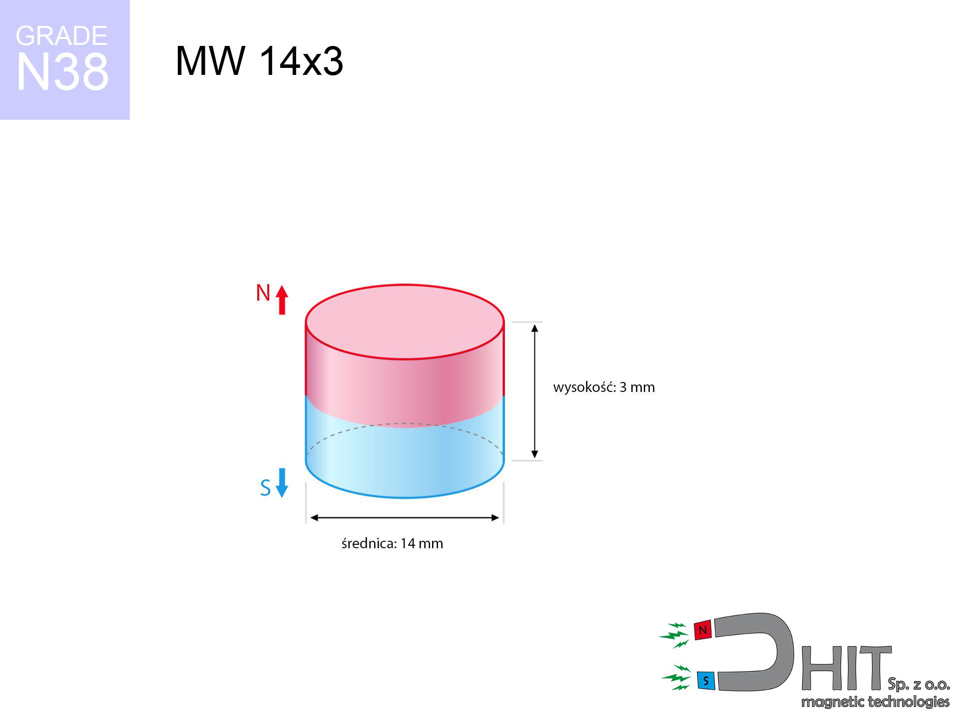
MW 14x3 / N38 - cylindrical magnet
cylindrical magnet
Catalog no 010025
GTIN/EAN: 5906301810247
Diameter Ø
14 mm [±0,1 mm]
Height
3 mm [±0,1 mm]
Weight
3.46 g
Magnetization Direction
↑ axial
Load capacity
2.76 kg / 27.06 N
Magnetic Induction
244.11 mT / 2441 Gs
Coating
[NiCuNi] Nickel
1.845 ZŁ with VAT / pcs + price for transport
1.500 ZŁ net + 23% VAT / pcs
bulk discounts:
Need more?
Pick up the phone and ask
+48 888 99 98 98
alternatively drop us a message via
request form
through our site.
Specifications and appearance of neodymium magnets can be checked using our
online calculation tool.
Order by 14:00 and we’ll ship today!
Product card - MW 14x3 / N38 - cylindrical magnet
Specification / characteristics - MW 14x3 / N38 - cylindrical magnet
| properties | values |
|---|---|
| Cat. no. | 010025 |
| GTIN/EAN | 5906301810247 |
| Production/Distribution | Dhit sp. z o.o. |
| Country of origin | Poland / China / Germany |
| Customs code | 85059029 |
| Diameter Ø | 14 mm [±0,1 mm] |
| Height | 3 mm [±0,1 mm] |
| Weight | 3.46 g |
| Magnetization Direction | ↑ axial |
| Load capacity ~ ? | 2.76 kg / 27.06 N |
| Magnetic Induction ~ ? | 244.11 mT / 2441 Gs |
| Coating | [NiCuNi] Nickel |
| Manufacturing Tolerance | ±0.1 mm |
Magnetic properties of material N38
| properties | values | units |
|---|---|---|
| remenance Br [min. - max.] ? | 12.2-12.6 | kGs |
| remenance Br [min. - max.] ? | 1220-1260 | mT |
| coercivity bHc ? | 10.8-11.5 | kOe |
| coercivity bHc ? | 860-915 | kA/m |
| actual internal force iHc | ≥ 12 | kOe |
| actual internal force iHc | ≥ 955 | kA/m |
| energy density [min. - max.] ? | 36-38 | BH max MGOe |
| energy density [min. - max.] ? | 287-303 | BH max KJ/m |
| max. temperature ? | ≤ 80 | °C |
Physical properties of sintered neodymium magnets Nd2Fe14B at 20°C
| properties | values | units |
|---|---|---|
| Vickers hardness | ≥550 | Hv |
| Density | ≥7.4 | g/cm3 |
| Curie Temperature TC | 312 - 380 | °C |
| Curie Temperature TF | 593 - 716 | °F |
| Specific resistance | 150 | μΩ⋅cm |
| Bending strength | 250 | MPa |
| Compressive strength | 1000~1100 | MPa |
| Thermal expansion parallel (∥) to orientation (M) | (3-4) x 10-6 | °C-1 |
| Thermal expansion perpendicular (⊥) to orientation (M) | -(1-3) x 10-6 | °C-1 |
| Young's modulus | 1.7 x 10⁴ | kg/mm² |
Technical modeling of the product - technical parameters
These data are the result of a engineering calculation. Values rely on algorithms for the class Nd2Fe14B. Actual parameters might slightly deviate from the simulation results. Treat these data as a reference point when designing systems.
Table 1: Static pull force (force vs distance) - power drop
MW 14x3 / N38
| Distance (mm) | Induction (Gauss) / mT | Pull Force (kg/lbs/g/N) | Risk Status |
|---|---|---|---|
| 0 mm |
2440 Gs
244.0 mT
|
2.76 kg / 6.08 LBS
2760.0 g / 27.1 N
|
warning |
| 1 mm |
2199 Gs
219.9 mT
|
2.24 kg / 4.94 LBS
2241.6 g / 22.0 N
|
warning |
| 2 mm |
1900 Gs
190.0 mT
|
1.67 kg / 3.69 LBS
1673.8 g / 16.4 N
|
low risk |
| 3 mm |
1593 Gs
159.3 mT
|
1.18 kg / 2.59 LBS
1175.5 g / 11.5 N
|
low risk |
| 5 mm |
1062 Gs
106.2 mT
|
0.52 kg / 1.15 LBS
523.0 g / 5.1 N
|
low risk |
| 10 mm |
380 Gs
38.0 mT
|
0.07 kg / 0.15 LBS
66.8 g / 0.7 N
|
low risk |
| 15 mm |
160 Gs
16.0 mT
|
0.01 kg / 0.03 LBS
11.9 g / 0.1 N
|
low risk |
| 20 mm |
79 Gs
7.9 mT
|
0.00 kg / 0.01 LBS
2.9 g / 0.0 N
|
low risk |
| 30 mm |
27 Gs
2.7 mT
|
0.00 kg / 0.00 LBS
0.3 g / 0.0 N
|
low risk |
| 50 mm |
7 Gs
0.7 mT
|
0.00 kg / 0.00 LBS
0.0 g / 0.0 N
|
low risk |
Table 2: Vertical force (vertical surface)
MW 14x3 / N38
| Distance (mm) | Friction coefficient | Pull Force (kg/lbs/g/N) |
|---|---|---|
| 0 mm | Stal (~0.2) |
0.55 kg / 1.22 LBS
552.0 g / 5.4 N
|
| 1 mm | Stal (~0.2) |
0.45 kg / 0.99 LBS
448.0 g / 4.4 N
|
| 2 mm | Stal (~0.2) |
0.33 kg / 0.74 LBS
334.0 g / 3.3 N
|
| 3 mm | Stal (~0.2) |
0.24 kg / 0.52 LBS
236.0 g / 2.3 N
|
| 5 mm | Stal (~0.2) |
0.10 kg / 0.23 LBS
104.0 g / 1.0 N
|
| 10 mm | Stal (~0.2) |
0.01 kg / 0.03 LBS
14.0 g / 0.1 N
|
| 15 mm | Stal (~0.2) |
0.00 kg / 0.00 LBS
2.0 g / 0.0 N
|
| 20 mm | Stal (~0.2) |
0.00 kg / 0.00 LBS
0.0 g / 0.0 N
|
| 30 mm | Stal (~0.2) |
0.00 kg / 0.00 LBS
0.0 g / 0.0 N
|
| 50 mm | Stal (~0.2) |
0.00 kg / 0.00 LBS
0.0 g / 0.0 N
|
Table 3: Vertical assembly (shearing) - vertical pull
MW 14x3 / N38
| Surface type | Friction coefficient / % Mocy | Max load (kg/lbs/g/N) |
|---|---|---|
| Raw steel |
µ = 0.3
30% Nominalnej Siły
|
0.83 kg / 1.83 LBS
828.0 g / 8.1 N
|
| Painted steel (standard) |
µ = 0.2
20% Nominalnej Siły
|
0.55 kg / 1.22 LBS
552.0 g / 5.4 N
|
| Oily/slippery steel |
µ = 0.1
10% Nominalnej Siły
|
0.28 kg / 0.61 LBS
276.0 g / 2.7 N
|
| Magnet with anti-slip rubber |
µ = 0.5
50% Nominalnej Siły
|
1.38 kg / 3.04 LBS
1380.0 g / 13.5 N
|
Table 4: Steel thickness (substrate influence) - sheet metal selection
MW 14x3 / N38
| Steel thickness (mm) | % power | Real pull force (kg/lbs/g/N) |
|---|---|---|
| 0.5 mm |
|
0.28 kg / 0.61 LBS
276.0 g / 2.7 N
|
| 1 mm |
|
0.69 kg / 1.52 LBS
690.0 g / 6.8 N
|
| 2 mm |
|
1.38 kg / 3.04 LBS
1380.0 g / 13.5 N
|
| 3 mm |
|
2.07 kg / 4.56 LBS
2070.0 g / 20.3 N
|
| 5 mm |
|
2.76 kg / 6.08 LBS
2760.0 g / 27.1 N
|
| 10 mm |
|
2.76 kg / 6.08 LBS
2760.0 g / 27.1 N
|
| 11 mm |
|
2.76 kg / 6.08 LBS
2760.0 g / 27.1 N
|
| 12 mm |
|
2.76 kg / 6.08 LBS
2760.0 g / 27.1 N
|
Table 5: Thermal stability (stability) - resistance threshold
MW 14x3 / N38
| Ambient temp. (°C) | Power loss | Remaining pull (kg/lbs/g/N) | Status |
|---|---|---|---|
| 20 °C | 0.0% |
2.76 kg / 6.08 LBS
2760.0 g / 27.1 N
|
OK |
| 40 °C | -2.2% |
2.70 kg / 5.95 LBS
2699.3 g / 26.5 N
|
OK |
| 60 °C | -4.4% |
2.64 kg / 5.82 LBS
2638.6 g / 25.9 N
|
|
| 80 °C | -6.6% |
2.58 kg / 5.68 LBS
2577.8 g / 25.3 N
|
|
| 100 °C | -28.8% |
1.97 kg / 4.33 LBS
1965.1 g / 19.3 N
|
Table 6: Magnet-Magnet interaction (attraction) - field range
MW 14x3 / N38
| Gap (mm) | Attraction (kg/lbs) (N-S) | Lateral Force (kg/lbs/g/N) | Repulsion (kg/lbs) (N-N) |
|---|---|---|---|
| 0 mm |
5.65 kg / 12.46 LBS
4 030 Gs
|
0.85 kg / 1.87 LBS
848 g / 8.3 N
|
N/A |
| 1 mm |
5.16 kg / 11.37 LBS
4 662 Gs
|
0.77 kg / 1.71 LBS
773 g / 7.6 N
|
4.64 kg / 10.23 LBS
~0 Gs
|
| 2 mm |
4.59 kg / 10.12 LBS
4 398 Gs
|
0.69 kg / 1.52 LBS
689 g / 6.8 N
|
4.13 kg / 9.11 LBS
~0 Gs
|
| 3 mm |
4.00 kg / 8.82 LBS
4 107 Gs
|
0.60 kg / 1.32 LBS
600 g / 5.9 N
|
3.60 kg / 7.94 LBS
~0 Gs
|
| 5 mm |
2.89 kg / 6.37 LBS
3 490 Gs
|
0.43 kg / 0.96 LBS
434 g / 4.3 N
|
2.60 kg / 5.74 LBS
~0 Gs
|
| 10 mm |
1.07 kg / 2.36 LBS
2 125 Gs
|
0.16 kg / 0.35 LBS
161 g / 1.6 N
|
0.96 kg / 2.12 LBS
~0 Gs
|
| 20 mm |
0.14 kg / 0.30 LBS
759 Gs
|
0.02 kg / 0.05 LBS
21 g / 0.2 N
|
0.12 kg / 0.27 LBS
~0 Gs
|
| 50 mm |
0.00 kg / 0.00 LBS
89 Gs
|
0.00 kg / 0.00 LBS
0 g / 0.0 N
|
0.00 kg / 0.00 LBS
~0 Gs
|
| 60 mm |
0.00 kg / 0.00 LBS
54 Gs
|
0.00 kg / 0.00 LBS
0 g / 0.0 N
|
0.00 kg / 0.00 LBS
~0 Gs
|
| 70 mm |
0.00 kg / 0.00 LBS
36 Gs
|
0.00 kg / 0.00 LBS
0 g / 0.0 N
|
0.00 kg / 0.00 LBS
~0 Gs
|
| 80 mm |
0.00 kg / 0.00 LBS
25 Gs
|
0.00 kg / 0.00 LBS
0 g / 0.0 N
|
0.00 kg / 0.00 LBS
~0 Gs
|
| 90 mm |
0.00 kg / 0.00 LBS
18 Gs
|
0.00 kg / 0.00 LBS
0 g / 0.0 N
|
0.00 kg / 0.00 LBS
~0 Gs
|
| 100 mm |
0.00 kg / 0.00 LBS
13 Gs
|
0.00 kg / 0.00 LBS
0 g / 0.0 N
|
0.00 kg / 0.00 LBS
~0 Gs
|
Table 7: Protective zones (implants) - warnings
MW 14x3 / N38
| Object / Device | Limit (Gauss) / mT | Safe distance |
|---|---|---|
| Pacemaker | 5 Gs (0.5 mT) | 5.5 cm |
| Hearing aid | 10 Gs (1.0 mT) | 4.5 cm |
| Timepiece | 20 Gs (2.0 mT) | 3.5 cm |
| Mobile device | 40 Gs (4.0 mT) | 3.0 cm |
| Car key | 50 Gs (5.0 mT) | 2.5 cm |
| Payment card | 400 Gs (40.0 mT) | 1.0 cm |
| HDD hard drive | 600 Gs (60.0 mT) | 1.0 cm |
Table 8: Impact energy (kinetic energy) - collision effects
MW 14x3 / N38
| Start from (mm) | Speed (km/h) | Energy (J) | Predicted outcome |
|---|---|---|---|
| 10 mm |
28.91 km/h
(8.03 m/s)
|
0.11 J | |
| 30 mm |
49.34 km/h
(13.71 m/s)
|
0.32 J | |
| 50 mm |
63.69 km/h
(17.69 m/s)
|
0.54 J | |
| 100 mm |
90.07 km/h
(25.02 m/s)
|
1.08 J |
Table 9: Anti-corrosion coating durability
MW 14x3 / N38
| Technical parameter | Value / Description |
|---|---|
| Coating type | [NiCuNi] Nickel |
| Layer structure | Nickel - Copper - Nickel |
| Layer thickness | 10-20 µm |
| Salt spray test (SST) ? | 24 h |
| Recommended environment | Indoors only (dry) |
Table 10: Construction data (Flux)
MW 14x3 / N38
| Parameter | Value | SI Unit / Description |
|---|---|---|
| Magnetic Flux | 4 301 Mx | 43.0 µWb |
| Pc Coefficient | 0.31 | Low (Flat) |
Table 11: Physics of underwater searching
MW 14x3 / N38
| Environment | Effective steel pull | Effect |
|---|---|---|
| Air (land) | 2.76 kg | Standard |
| Water (riverbed) |
3.16 kg
(+0.40 kg buoyancy gain)
|
+14.5% |
1. Shear force
*Caution: On a vertical surface, the magnet holds only ~20% of its max power.
2. Efficiency vs thickness
*Thin metal sheet (e.g. 0.5mm PC case) severely limits the holding force.
3. Power loss vs temp
*For N38 grade, the safety limit is 80°C.
4. Demagnetization curve and operating point (B-H)
chart generated for the permeance coefficient Pc (Permeance Coefficient) = 0.31
This simulation demonstrates the magnetic stability of the selected magnet under specific geometric conditions. The solid red line represents the demagnetization curve (material potential), while the dashed blue line is the load line based on the magnet's geometry. The Pc (Permeance Coefficient), also known as the load line slope, is a dimensionless value that describes the relationship between the magnet's shape and its magnetic stability. The intersection of these two lines (the black dot) is the operating point — it determines the actual magnetic flux density generated by the magnet in this specific configuration. A higher Pc value means the magnet is more 'slender' (tall relative to its area), resulting in a higher operating point and better resistance to irreversible demagnetization caused by external fields or temperature. A value of 0.42 is relatively low (typical for flat magnets), meaning the operating point is closer to the 'knee' of the curve — caution is advised when operating at temperatures near the maximum limit to avoid strength loss.
Elemental analysis
| iron (Fe) | 64% – 68% |
| neodymium (Nd) | 29% – 32% |
| boron (B) | 1.1% – 1.2% |
| dysprosium (Dy) | 0.5% – 2.0% |
| coating (Ni-Cu-Ni) | < 0.05% |
Ecology and recycling (GPSR)
| recyclability (EoL) | 100% |
| recycled raw materials | ~10% (pre-cons) |
| carbon footprint | low / zredukowany |
| waste code (EWC) | 16 02 16 |
See also offers
![SM 32x475 [2xM8] / N52 - magnetic separator](https://cdn3.dhit.pl/graphics/products/sm-32x475-2xm8-wef.jpg "SM 32x475 [2xM8] / N52 - magnetic separator")


Advantages as well as disadvantages of Nd2Fe14B magnets.
Strengths
- They retain magnetic properties for nearly 10 years – the loss is just ~1% (according to analyses),
- Magnets perfectly defend themselves against loss of magnetization caused by external fields,
- A magnet with a metallic silver surface has an effective appearance,
- Neodymium magnets deliver maximum magnetic induction on a contact point, which increases force concentration,
- Thanks to resistance to high temperature, they can operate (depending on the form) even at temperatures up to 230°C and higher...
- Thanks to versatility in constructing and the ability to modify to complex applications,
- Fundamental importance in modern technologies – they are commonly used in data components, brushless drives, precision medical tools, and other advanced devices.
- Compactness – despite small sizes they provide effective action, making them ideal for precision applications
Cons
- They are prone to damage upon heavy impacts. To avoid cracks, it is worth protecting magnets in special housings. Such protection not only shields the magnet but also improves its resistance to damage
- Neodymium magnets lose force when exposed to high temperatures. After reaching 80°C, many of them experience permanent weakening of strength (a factor is the shape and dimensions of the magnet). We offer magnets specially adapted to work at temperatures up to 230°C marked [AH], which are extremely resistant to heat
- When exposed to humidity, magnets usually rust. To use them in conditions outside, it is recommended to use protective magnets, such as magnets in rubber or plastics, which secure oxidation as well as corrosion.
- Limited ability of creating nuts in the magnet and complicated shapes - recommended is a housing - mounting mechanism.
- Possible danger related to microscopic parts of magnets are risky, if swallowed, which becomes key in the context of child health protection. Additionally, small components of these devices can complicate diagnosis medical in case of swallowing.
- With mass production the cost of neodymium magnets is economically unviable,
Pull force analysis
Detachment force of the magnet in optimal conditions – what it depends on?
- on a base made of mild steel, optimally conducting the magnetic flux
- possessing a thickness of min. 10 mm to ensure full flux closure
- with a surface cleaned and smooth
- under conditions of gap-free contact (surface-to-surface)
- for force applied at a right angle (pull-off, not shear)
- at standard ambient temperature
What influences lifting capacity in practice
- Gap (between the magnet and the plate), as even a microscopic distance (e.g. 0.5 mm) can cause a decrease in lifting capacity by up to 50% (this also applies to paint, corrosion or dirt).
- Angle of force application – highest force is available only during perpendicular pulling. The shear force of the magnet along the surface is standardly many times smaller (approx. 1/5 of the lifting capacity).
- Base massiveness – too thin sheet does not accept the full field, causing part of the flux to be lost into the air.
- Chemical composition of the base – mild steel attracts best. Alloy steels decrease magnetic permeability and holding force.
- Plate texture – smooth surfaces ensure maximum contact, which increases field saturation. Rough surfaces weaken the grip.
- Heat – neodymium magnets have a sensitivity to temperature. At higher temperatures they lose power, and in frost gain strength (up to a certain limit).
Lifting capacity was determined with the use of a smooth steel plate of suitable thickness (min. 20 mm), under perpendicular pulling force, however under attempts to slide the magnet the holding force is lower. Additionally, even a slight gap between the magnet’s surface and the plate decreases the lifting capacity.
H&S for magnets
Choking Hazard
Always keep magnets out of reach of children. Risk of swallowing is high, and the consequences of magnets clamping inside the body are tragic.
Data carriers
Device Safety: Neodymium magnets can ruin data carriers and sensitive devices (heart implants, hearing aids, timepieces).
Metal Allergy
Medical facts indicate that nickel (the usual finish) is a common allergen. For allergy sufferers, prevent touching magnets with bare hands and opt for versions in plastic housing.
Do not drill into magnets
Fire hazard: Neodymium dust is explosive. Avoid machining magnets in home conditions as this risks ignition.
Pacemakers
Medical warning: Strong magnets can turn off heart devices and defibrillators. Do not approach if you have medical devices.
Immense force
Be careful. Neodymium magnets act from a long distance and connect with massive power, often quicker than you can move away.
Physical harm
Pinching hazard: The pulling power is so immense that it can cause hematomas, pinching, and even bone fractures. Protective gloves are recommended.
Operating temperature
Do not overheat. Neodymium magnets are susceptible to heat. If you require resistance above 80°C, ask us about HT versions (H, SH, UH).
Impact on smartphones
GPS units and smartphones are extremely sensitive to magnetism. Direct contact with a strong magnet can ruin the internal compass in your phone.
Eye protection
NdFeB magnets are ceramic materials, which means they are prone to chipping. Collision of two magnets will cause them breaking into small pieces.
Tabela kosztu i czasu dostawy
Płatność przed wysyłką:

GLS kurier
Przesyłka będzie u Ciebie za 2-3 dni
14.99 ZŁ

InPost Paczkomaty 24/7
Przesyłka będzie u Ciebie za 1-2 dni
12.30 ZŁ
Płatność przy odbiorze (pobranie):
GLS kurier
Przesyłka będzie u Ciebie za 1-2 dni
23.00 ZŁ
Rate the product
Your rating