

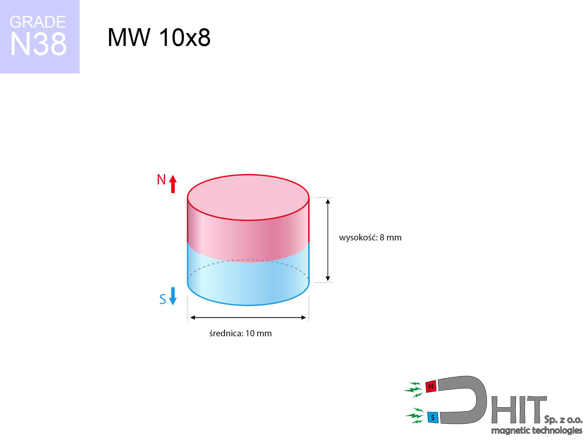
MW 10x8 / N38 - cylindrical magnet
cylindrical magnet
Catalog no 010013
GTIN/EAN: 5906301810124
Diameter Ø
10 mm [±0,1 mm]
Height
8 mm [±0,1 mm]
Weight
4.71 g
Magnetization Direction
↑ axial
Load capacity
3.38 kg / 33.16 N
Magnetic Induction
525.10 mT / 5251 Gs
Coating
[NiCuNi] Nickel
2.18 ZŁ with VAT / pcs + price for transport
1.770 ZŁ net + 23% VAT / pcs
bulk discounts:
Need more?
Contact us by phone
+48 888 99 98 98
or drop us a message by means of
contact form
our website.
Parameters and appearance of magnetic components can be calculated using our
our magnetic calculator.
Order by 14:00 and we’ll ship today!
Technical details - MW 10x8 / N38 - cylindrical magnet
Specification / characteristics - MW 10x8 / N38 - cylindrical magnet
| properties | values |
|---|---|
| Cat. no. | 010013 |
| GTIN/EAN | 5906301810124 |
| Production/Distribution | Dhit sp. z o.o. |
| Country of origin | Poland / China / Germany |
| Customs code | 85059029 |
| Diameter Ø | 10 mm [±0,1 mm] |
| Height | 8 mm [±0,1 mm] |
| Weight | 4.71 g |
| Magnetization Direction | ↑ axial |
| Load capacity ~ ? | 3.38 kg / 33.16 N |
| Magnetic Induction ~ ? | 525.10 mT / 5251 Gs |
| Coating | [NiCuNi] Nickel |
| Manufacturing Tolerance | ±0.1 mm |
Magnetic properties of material N38
| properties | values | units |
|---|---|---|
| remenance Br [min. - max.] ? | 12.2-12.6 | kGs |
| remenance Br [min. - max.] ? | 1220-1260 | mT |
| coercivity bHc ? | 10.8-11.5 | kOe |
| coercivity bHc ? | 860-915 | kA/m |
| actual internal force iHc | ≥ 12 | kOe |
| actual internal force iHc | ≥ 955 | kA/m |
| energy density [min. - max.] ? | 36-38 | BH max MGOe |
| energy density [min. - max.] ? | 287-303 | BH max KJ/m |
| max. temperature ? | ≤ 80 | °C |
Physical properties of sintered neodymium magnets Nd2Fe14B at 20°C
| properties | values | units |
|---|---|---|
| Vickers hardness | ≥550 | Hv |
| Density | ≥7.4 | g/cm3 |
| Curie Temperature TC | 312 - 380 | °C |
| Curie Temperature TF | 593 - 716 | °F |
| Specific resistance | 150 | μΩ⋅cm |
| Bending strength | 250 | MPa |
| Compressive strength | 1000~1100 | MPa |
| Thermal expansion parallel (∥) to orientation (M) | (3-4) x 10-6 | °C-1 |
| Thermal expansion perpendicular (⊥) to orientation (M) | -(1-3) x 10-6 | °C-1 |
| Young's modulus | 1.7 x 10⁴ | kg/mm² |
Technical simulation of the magnet - report
Presented data constitute the outcome of a physical calculation. Results were calculated on algorithms for the material Nd2Fe14B. Actual performance may differ from theoretical values. Please consider these data as a reference point during assembly planning.
Table 1: Static force (force vs distance) - interaction chart
MW 10x8 / N38
| Distance (mm) | Induction (Gauss) / mT | Pull Force (kg/lbs/g/N) | Risk Status |
|---|---|---|---|
| 0 mm |
5247 Gs
524.7 mT
|
3.38 kg / 7.45 lbs
3380.0 g / 33.2 N
|
strong |
| 1 mm |
4204 Gs
420.4 mT
|
2.17 kg / 4.78 lbs
2169.6 g / 21.3 N
|
strong |
| 2 mm |
3243 Gs
324.3 mT
|
1.29 kg / 2.85 lbs
1291.0 g / 12.7 N
|
safe |
| 3 mm |
2454 Gs
245.4 mT
|
0.74 kg / 1.63 lbs
739.6 g / 7.3 N
|
safe |
| 5 mm |
1403 Gs
140.3 mT
|
0.24 kg / 0.53 lbs
241.5 g / 2.4 N
|
safe |
| 10 mm |
428 Gs
42.8 mT
|
0.02 kg / 0.05 lbs
22.5 g / 0.2 N
|
safe |
| 15 mm |
177 Gs
17.7 mT
|
0.00 kg / 0.01 lbs
3.8 g / 0.0 N
|
safe |
| 20 mm |
89 Gs
8.9 mT
|
0.00 kg / 0.00 lbs
1.0 g / 0.0 N
|
safe |
| 30 mm |
31 Gs
3.1 mT
|
0.00 kg / 0.00 lbs
0.1 g / 0.0 N
|
safe |
| 50 mm |
8 Gs
0.8 mT
|
0.00 kg / 0.00 lbs
0.0 g / 0.0 N
|
safe |
Table 2: Vertical force (wall)
MW 10x8 / N38
| Distance (mm) | Friction coefficient | Pull Force (kg/lbs/g/N) |
|---|---|---|
| 0 mm | Stal (~0.2) |
0.68 kg / 1.49 lbs
676.0 g / 6.6 N
|
| 1 mm | Stal (~0.2) |
0.43 kg / 0.96 lbs
434.0 g / 4.3 N
|
| 2 mm | Stal (~0.2) |
0.26 kg / 0.57 lbs
258.0 g / 2.5 N
|
| 3 mm | Stal (~0.2) |
0.15 kg / 0.33 lbs
148.0 g / 1.5 N
|
| 5 mm | Stal (~0.2) |
0.05 kg / 0.11 lbs
48.0 g / 0.5 N
|
| 10 mm | Stal (~0.2) |
0.00 kg / 0.01 lbs
4.0 g / 0.0 N
|
| 15 mm | Stal (~0.2) |
0.00 kg / 0.00 lbs
0.0 g / 0.0 N
|
| 20 mm | Stal (~0.2) |
0.00 kg / 0.00 lbs
0.0 g / 0.0 N
|
| 30 mm | Stal (~0.2) |
0.00 kg / 0.00 lbs
0.0 g / 0.0 N
|
| 50 mm | Stal (~0.2) |
0.00 kg / 0.00 lbs
0.0 g / 0.0 N
|
Table 3: Vertical assembly (sliding) - behavior on slippery surfaces
MW 10x8 / N38
| Surface type | Friction coefficient / % Mocy | Max load (kg/lbs/g/N) |
|---|---|---|
| Raw steel |
µ = 0.3
30% Nominalnej Siły
|
1.01 kg / 2.24 lbs
1014.0 g / 9.9 N
|
| Painted steel (standard) |
µ = 0.2
20% Nominalnej Siły
|
0.68 kg / 1.49 lbs
676.0 g / 6.6 N
|
| Oily/slippery steel |
µ = 0.1
10% Nominalnej Siły
|
0.34 kg / 0.75 lbs
338.0 g / 3.3 N
|
| Magnet with anti-slip rubber |
µ = 0.5
50% Nominalnej Siły
|
1.69 kg / 3.73 lbs
1690.0 g / 16.6 N
|
Table 4: Material efficiency (saturation) - sheet metal selection
MW 10x8 / N38
| Steel thickness (mm) | % power | Real pull force (kg/lbs/g/N) |
|---|---|---|
| 0.5 mm |
|
0.34 kg / 0.75 lbs
338.0 g / 3.3 N
|
| 1 mm |
|
0.85 kg / 1.86 lbs
845.0 g / 8.3 N
|
| 2 mm |
|
1.69 kg / 3.73 lbs
1690.0 g / 16.6 N
|
| 3 mm |
|
2.54 kg / 5.59 lbs
2535.0 g / 24.9 N
|
| 5 mm |
|
3.38 kg / 7.45 lbs
3380.0 g / 33.2 N
|
| 10 mm |
|
3.38 kg / 7.45 lbs
3380.0 g / 33.2 N
|
| 11 mm |
|
3.38 kg / 7.45 lbs
3380.0 g / 33.2 N
|
| 12 mm |
|
3.38 kg / 7.45 lbs
3380.0 g / 33.2 N
|
Table 5: Thermal stability (stability) - thermal limit
MW 10x8 / N38
| Ambient temp. (°C) | Power loss | Remaining pull (kg/lbs/g/N) | Status |
|---|---|---|---|
| 20 °C | 0.0% |
3.38 kg / 7.45 lbs
3380.0 g / 33.2 N
|
OK |
| 40 °C | -2.2% |
3.31 kg / 7.29 lbs
3305.6 g / 32.4 N
|
OK |
| 60 °C | -4.4% |
3.23 kg / 7.12 lbs
3231.3 g / 31.7 N
|
OK |
| 80 °C | -6.6% |
3.16 kg / 6.96 lbs
3156.9 g / 31.0 N
|
|
| 100 °C | -28.8% |
2.41 kg / 5.31 lbs
2406.6 g / 23.6 N
|
Table 6: Magnet-Magnet interaction (attraction) - field range
MW 10x8 / N38
| Gap (mm) | Attraction (kg/lbs) (N-S) | Shear Force (kg/lbs/g/N) | Repulsion (kg/lbs) (N-N) |
|---|---|---|---|
| 0 mm |
13.33 kg / 29.39 lbs
5 906 Gs
|
2.00 kg / 4.41 lbs
2000 g / 19.6 N
|
N/A |
| 1 mm |
10.82 kg / 23.85 lbs
9 454 Gs
|
1.62 kg / 3.58 lbs
1623 g / 15.9 N
|
9.74 kg / 21.47 lbs
~0 Gs
|
| 2 mm |
8.56 kg / 18.86 lbs
8 408 Gs
|
1.28 kg / 2.83 lbs
1284 g / 12.6 N
|
7.70 kg / 16.98 lbs
~0 Gs
|
| 3 mm |
6.65 kg / 14.65 lbs
7 410 Gs
|
1.00 kg / 2.20 lbs
997 g / 9.8 N
|
5.98 kg / 13.19 lbs
~0 Gs
|
| 5 mm |
3.86 kg / 8.52 lbs
5 650 Gs
|
0.58 kg / 1.28 lbs
580 g / 5.7 N
|
3.48 kg / 7.67 lbs
~0 Gs
|
| 10 mm |
0.95 kg / 2.10 lbs
2 805 Gs
|
0.14 kg / 0.32 lbs
143 g / 1.4 N
|
0.86 kg / 1.89 lbs
~0 Gs
|
| 20 mm |
0.09 kg / 0.20 lbs
857 Gs
|
0.01 kg / 0.03 lbs
13 g / 0.1 N
|
0.08 kg / 0.18 lbs
~0 Gs
|
| 50 mm |
0.00 kg / 0.00 lbs
101 Gs
|
0.00 kg / 0.00 lbs
0 g / 0.0 N
|
0.00 kg / 0.00 lbs
~0 Gs
|
| 60 mm |
0.00 kg / 0.00 lbs
63 Gs
|
0.00 kg / 0.00 lbs
0 g / 0.0 N
|
0.00 kg / 0.00 lbs
~0 Gs
|
| 70 mm |
0.00 kg / 0.00 lbs
42 Gs
|
0.00 kg / 0.00 lbs
0 g / 0.0 N
|
0.00 kg / 0.00 lbs
~0 Gs
|
| 80 mm |
0.00 kg / 0.00 lbs
29 Gs
|
0.00 kg / 0.00 lbs
0 g / 0.0 N
|
0.00 kg / 0.00 lbs
~0 Gs
|
| 90 mm |
0.00 kg / 0.00 lbs
21 Gs
|
0.00 kg / 0.00 lbs
0 g / 0.0 N
|
0.00 kg / 0.00 lbs
~0 Gs
|
| 100 mm |
0.00 kg / 0.00 lbs
16 Gs
|
0.00 kg / 0.00 lbs
0 g / 0.0 N
|
0.00 kg / 0.00 lbs
~0 Gs
|
Table 7: Safety (HSE) (implants) - warnings
MW 10x8 / N38
| Object / Device | Limit (Gauss) / mT | Safe distance |
|---|---|---|
| Pacemaker | 5 Gs (0.5 mT) | 6.0 cm |
| Hearing aid | 10 Gs (1.0 mT) | 5.0 cm |
| Timepiece | 20 Gs (2.0 mT) | 4.0 cm |
| Mobile device | 40 Gs (4.0 mT) | 3.0 cm |
| Car key | 50 Gs (5.0 mT) | 3.0 cm |
| Payment card | 400 Gs (40.0 mT) | 1.5 cm |
| HDD hard drive | 600 Gs (60.0 mT) | 1.0 cm |
Table 8: Impact energy (kinetic energy) - warning
MW 10x8 / N38
| Start from (mm) | Speed (km/h) | Energy (J) | Predicted outcome |
|---|---|---|---|
| 10 mm |
27.13 km/h
(7.54 m/s)
|
0.13 J | |
| 30 mm |
46.80 km/h
(13.00 m/s)
|
0.40 J | |
| 50 mm |
60.41 km/h
(16.78 m/s)
|
0.66 J | |
| 100 mm |
85.43 km/h
(23.73 m/s)
|
1.33 J |
Table 9: Anti-corrosion coating durability
MW 10x8 / N38
| Technical parameter | Value / Description |
|---|---|
| Coating type | [NiCuNi] Nickel |
| Layer structure | Nickel - Copper - Nickel |
| Layer thickness | 10-20 µm |
| Salt spray test (SST) ? | 24 h |
| Recommended environment | Indoors only (dry) |
Table 10: Electrical data (Pc)
MW 10x8 / N38
| Parameter | Value | SI Unit / Description |
|---|---|---|
| Magnetic Flux | 4 183 Mx | 41.8 µWb |
| Pc Coefficient | 0.79 | High (Stable) |
Table 11: Physics of underwater searching
MW 10x8 / N38
| Environment | Effective steel pull | Effect |
|---|---|---|
| Air (land) | 3.38 kg | Standard |
| Water (riverbed) |
3.87 kg
(+0.49 kg buoyancy gain)
|
+14.5% |
1. Sliding resistance
*Note: On a vertical surface, the magnet holds merely approx. 20-30% of its nominal pull.
2. Steel saturation
*Thin steel (e.g. 0.5mm PC case) significantly reduces the holding force.
3. Heat tolerance
*For N38 material, the max working temp is 80°C.
4. Demagnetization curve and operating point (B-H)
chart generated for the permeance coefficient Pc (Permeance Coefficient) = 0.79
The chart above illustrates the magnetic characteristics of the material within the second quadrant of the hysteresis loop. The solid red line represents the demagnetization curve (material potential), while the dashed blue line is the load line based on the magnet's geometry. The Pc (Permeance Coefficient), also known as the load line slope, is a dimensionless value that describes the relationship between the magnet's shape and its magnetic stability. The intersection of these two lines (the black dot) is the operating point — it determines the actual magnetic flux density generated by the magnet in this specific configuration. A higher Pc value means the magnet is more 'slender' (tall relative to its area), resulting in a higher operating point and better resistance to irreversible demagnetization caused by external fields or temperature. A value of 0.42 is relatively low (typical for flat magnets), meaning the operating point is closer to the 'knee' of the curve — caution is advised when operating at temperatures near the maximum limit to avoid strength loss.
Chemical composition
| iron (Fe) | 64% – 68% |
| neodymium (Nd) | 29% – 32% |
| boron (B) | 1.1% – 1.2% |
| dysprosium (Dy) | 0.5% – 2.0% |
| coating (Ni-Cu-Ni) | < 0.05% |
Environmental data
| recyclability (EoL) | 100% |
| recycled raw materials | ~10% (pre-cons) |
| carbon footprint | low / zredukowany |
| waste code (EWC) | 16 02 16 |
Other deals


Strengths and weaknesses of Nd2Fe14B magnets.
Pros
- They retain attractive force for nearly 10 years – the drop is just ~1% (according to analyses),
- They have excellent resistance to weakening of magnetic properties when exposed to external magnetic sources,
- The use of an metallic layer of noble metals (nickel, gold, silver) causes the element to look better,
- The surface of neodymium magnets generates a intense magnetic field – this is a distinguishing feature,
- Thanks to resistance to high temperature, they are capable of working (depending on the form) even at temperatures up to 230°C and higher...
- Thanks to modularity in shaping and the capacity to adapt to complex applications,
- Universal use in future technologies – they are used in hard drives, electromotive mechanisms, medical equipment, and multitasking production systems.
- Compactness – despite small sizes they generate large force, making them ideal for precision applications
Weaknesses
- Brittleness is one of their disadvantages. Upon strong impact they can fracture. We advise keeping them in a strong case, which not only protects them against impacts but also raises their durability
- Neodymium magnets decrease their strength under the influence of heating. As soon as 80°C is exceeded, many of them start losing their force. Therefore, we recommend our special magnets marked [AH], which maintain durability even at temperatures up to 230°C
- When exposed to humidity, magnets usually rust. To use them in conditions outside, it is recommended to use protective magnets, such as magnets in rubber or plastics, which secure oxidation as well as corrosion.
- Due to limitations in realizing threads and complicated shapes in magnets, we recommend using cover - magnetic mount.
- Possible danger resulting from small fragments of magnets pose a threat, when accidentally swallowed, which becomes key in the aspect of protecting the youngest. Additionally, tiny parts of these products can be problematic in diagnostics medical when they are in the body.
- Higher cost of purchase is one of the disadvantages compared to ceramic magnets, especially in budget applications
Holding force characteristics
Maximum magnetic pulling force – what contributes to it?
- with the contact of a yoke made of special test steel, guaranteeing maximum field concentration
- whose thickness equals approx. 10 mm
- characterized by even structure
- under conditions of no distance (metal-to-metal)
- under perpendicular force direction (90-degree angle)
- at room temperature
Practical aspects of lifting capacity – factors
- Gap (between the magnet and the metal), because even a microscopic clearance (e.g. 0.5 mm) can cause a decrease in lifting capacity by up to 50% (this also applies to paint, corrosion or dirt).
- Direction of force – maximum parameter is available only during pulling at a 90° angle. The force required to slide of the magnet along the surface is typically many times smaller (approx. 1/5 of the lifting capacity).
- Plate thickness – too thin plate does not accept the full field, causing part of the power to be escaped into the air.
- Chemical composition of the base – low-carbon steel gives the best results. Higher carbon content reduce magnetic properties and holding force.
- Base smoothness – the smoother and more polished the surface, the better the adhesion and higher the lifting capacity. Roughness acts like micro-gaps.
- Thermal factor – high temperature reduces pulling force. Too high temperature can permanently demagnetize the magnet.
Holding force was checked on a smooth steel plate of 20 mm thickness, when a perpendicular force was applied, however under attempts to slide the magnet the load capacity is reduced by as much as 5 times. Moreover, even a small distance between the magnet’s surface and the plate decreases the load capacity.
Precautions when working with neodymium magnets
GPS Danger
GPS units and smartphones are extremely sensitive to magnetic fields. Close proximity with a strong magnet can ruin the internal compass in your phone.
Medical interference
Warning for patients: Strong magnetic fields affect medical devices. Maintain at least 30 cm distance or request help to handle the magnets.
Mechanical processing
Powder produced during cutting of magnets is self-igniting. Avoid drilling into magnets unless you are an expert.
Do not give to children
Absolutely store magnets away from children. Risk of swallowing is significant, and the consequences of magnets connecting inside the body are very dangerous.
Electronic hazard
Very strong magnetic fields can corrupt files on credit cards, HDDs, and other magnetic media. Keep a distance of min. 10 cm.
Physical harm
Mind your fingers. Two powerful magnets will join instantly with a force of massive weight, destroying everything in their path. Be careful!
Caution required
Handle with care. Neodymium magnets attract from a distance and snap with massive power, often quicker than you can move away.
Allergic reactions
Studies show that nickel (standard magnet coating) is a strong allergen. For allergy sufferers, refrain from touching magnets with bare hands and select versions in plastic housing.
Heat warning
Keep cool. Neodymium magnets are susceptible to temperature. If you need resistance above 80°C, look for special high-temperature series (H, SH, UH).
Material brittleness
Beware of splinters. Magnets can fracture upon violent connection, launching shards into the air. We recommend safety glasses.
Tabela kosztu i czasu dostawy
Płatność przed wysyłką:

GLS kurier
Przesyłka będzie u Ciebie za 2-3 dni
14.99 ZŁ

InPost Paczkomaty 24/7
Przesyłka będzie u Ciebie za 1-2 dni
12.30 ZŁ
Płatność przy odbiorze (pobranie):
GLS kurier
Przesyłka będzie u Ciebie za 1-2 dni
23.00 ZŁ
Rate the product
Your rating