
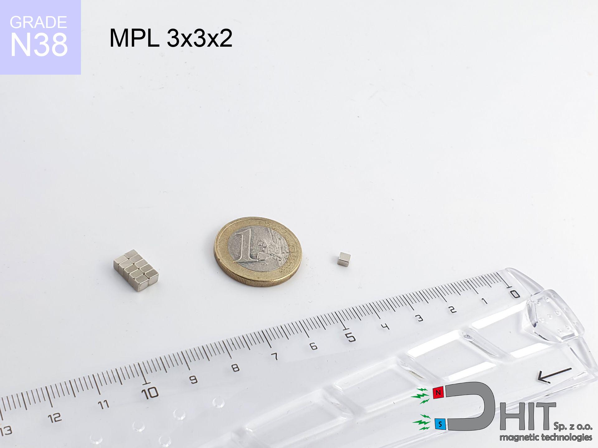
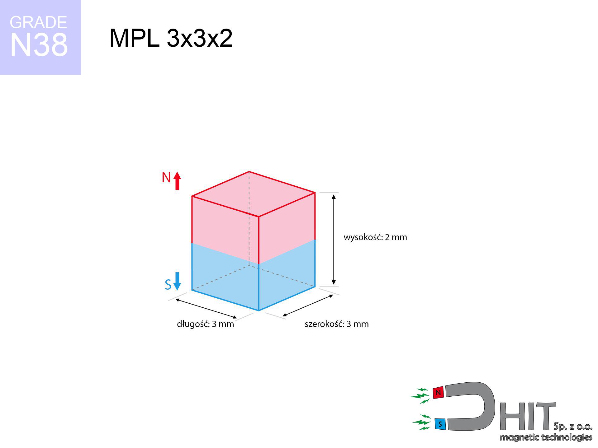
MPL 3x3x2 / N38 - lamellar magnet
lamellar magnet
Catalog no 020147
GTIN/EAN: 5906301811534
length
3 mm [±0,1 mm]
Width
3 mm [±0,1 mm]
Height
2 mm [±0,1 mm]
Weight
0.13 g
Magnetization Direction
↑ axial
Load capacity
0.36 kg / 3.49 N
Magnetic Induction
472.94 mT / 4729 Gs
Coating
[NiCuNi] Nickel
0.1722 ZŁ with VAT / pcs + price for transport
0.1400 ZŁ net + 23% VAT / pcs
bulk discounts:
Need more?
Call us now
+48 888 99 98 98
otherwise get in touch using
our online form
our website.
Weight and structure of magnetic components can be reviewed using our
power calculator.
Same-day processing for orders placed before 14:00.
Technical - MPL 3x3x2 / N38 - lamellar magnet
Specification / characteristics - MPL 3x3x2 / N38 - lamellar magnet
| properties | values |
|---|---|
| Cat. no. | 020147 |
| GTIN/EAN | 5906301811534 |
| Production/Distribution | Dhit sp. z o.o. |
| Country of origin | Poland / China / Germany |
| Customs code | 85059029 |
| length | 3 mm [±0,1 mm] |
| Width | 3 mm [±0,1 mm] |
| Height | 2 mm [±0,1 mm] |
| Weight | 0.13 g |
| Magnetization Direction | ↑ axial |
| Load capacity ~ ? | 0.36 kg / 3.49 N |
| Magnetic Induction ~ ? | 472.94 mT / 4729 Gs |
| Coating | [NiCuNi] Nickel |
| Manufacturing Tolerance | ±0.1 mm |
Magnetic properties of material N38
| properties | values | units |
|---|---|---|
| remenance Br [min. - max.] ? | 12.2-12.6 | kGs |
| remenance Br [min. - max.] ? | 1220-1260 | mT |
| coercivity bHc ? | 10.8-11.5 | kOe |
| coercivity bHc ? | 860-915 | kA/m |
| actual internal force iHc | ≥ 12 | kOe |
| actual internal force iHc | ≥ 955 | kA/m |
| energy density [min. - max.] ? | 36-38 | BH max MGOe |
| energy density [min. - max.] ? | 287-303 | BH max KJ/m |
| max. temperature ? | ≤ 80 | °C |
Physical properties of sintered neodymium magnets Nd2Fe14B at 20°C
| properties | values | units |
|---|---|---|
| Vickers hardness | ≥550 | Hv |
| Density | ≥7.4 | g/cm3 |
| Curie Temperature TC | 312 - 380 | °C |
| Curie Temperature TF | 593 - 716 | °F |
| Specific resistance | 150 | μΩ⋅cm |
| Bending strength | 250 | MPa |
| Compressive strength | 1000~1100 | MPa |
| Thermal expansion parallel (∥) to orientation (M) | (3-4) x 10-6 | °C-1 |
| Thermal expansion perpendicular (⊥) to orientation (M) | -(1-3) x 10-6 | °C-1 |
| Young's modulus | 1.7 x 10⁴ | kg/mm² |
Physical analysis of the assembly - technical parameters
These information constitute the outcome of a physical simulation. Values were calculated on algorithms for the class Nd2Fe14B. Actual performance may differ. Treat these calculations as a reference point for designers.
Table 1: Static pull force (pull vs gap) - interaction chart
MPL 3x3x2 / N38
| Distance (mm) | Induction (Gauss) / mT | Pull Force (kg/lbs/g/N) | Risk Status |
|---|---|---|---|
| 0 mm |
4719 Gs
471.9 mT
|
0.36 kg / 0.79 pounds
360.0 g / 3.5 N
|
low risk |
| 1 mm |
2223 Gs
222.3 mT
|
0.08 kg / 0.18 pounds
79.9 g / 0.8 N
|
low risk |
| 2 mm |
966 Gs
96.6 mT
|
0.02 kg / 0.03 pounds
15.1 g / 0.1 N
|
low risk |
| 3 mm |
468 Gs
46.8 mT
|
0.00 kg / 0.01 pounds
3.5 g / 0.0 N
|
low risk |
| 5 mm |
153 Gs
15.3 mT
|
0.00 kg / 0.00 pounds
0.4 g / 0.0 N
|
low risk |
| 10 mm |
26 Gs
2.6 mT
|
0.00 kg / 0.00 pounds
0.0 g / 0.0 N
|
low risk |
| 15 mm |
9 Gs
0.9 mT
|
0.00 kg / 0.00 pounds
0.0 g / 0.0 N
|
low risk |
| 20 mm |
4 Gs
0.4 mT
|
0.00 kg / 0.00 pounds
0.0 g / 0.0 N
|
low risk |
| 30 mm |
1 Gs
0.1 mT
|
0.00 kg / 0.00 pounds
0.0 g / 0.0 N
|
low risk |
| 50 mm |
0 Gs
0.0 mT
|
0.00 kg / 0.00 pounds
0.0 g / 0.0 N
|
low risk |
Table 2: Vertical force (vertical surface)
MPL 3x3x2 / N38
| Distance (mm) | Friction coefficient | Pull Force (kg/lbs/g/N) |
|---|---|---|
| 0 mm | Stal (~0.2) |
0.07 kg / 0.16 pounds
72.0 g / 0.7 N
|
| 1 mm | Stal (~0.2) |
0.02 kg / 0.04 pounds
16.0 g / 0.2 N
|
| 2 mm | Stal (~0.2) |
0.00 kg / 0.01 pounds
4.0 g / 0.0 N
|
| 3 mm | Stal (~0.2) |
0.00 kg / 0.00 pounds
0.0 g / 0.0 N
|
| 5 mm | Stal (~0.2) |
0.00 kg / 0.00 pounds
0.0 g / 0.0 N
|
| 10 mm | Stal (~0.2) |
0.00 kg / 0.00 pounds
0.0 g / 0.0 N
|
| 15 mm | Stal (~0.2) |
0.00 kg / 0.00 pounds
0.0 g / 0.0 N
|
| 20 mm | Stal (~0.2) |
0.00 kg / 0.00 pounds
0.0 g / 0.0 N
|
| 30 mm | Stal (~0.2) |
0.00 kg / 0.00 pounds
0.0 g / 0.0 N
|
| 50 mm | Stal (~0.2) |
0.00 kg / 0.00 pounds
0.0 g / 0.0 N
|
Table 3: Vertical assembly (shearing) - vertical pull
MPL 3x3x2 / N38
| Surface type | Friction coefficient / % Mocy | Max load (kg/lbs/g/N) |
|---|---|---|
| Raw steel |
µ = 0.3
30% Nominalnej Siły
|
0.11 kg / 0.24 pounds
108.0 g / 1.1 N
|
| Painted steel (standard) |
µ = 0.2
20% Nominalnej Siły
|
0.07 kg / 0.16 pounds
72.0 g / 0.7 N
|
| Oily/slippery steel |
µ = 0.1
10% Nominalnej Siły
|
0.04 kg / 0.08 pounds
36.0 g / 0.4 N
|
| Magnet with anti-slip rubber |
µ = 0.5
50% Nominalnej Siły
|
0.18 kg / 0.40 pounds
180.0 g / 1.8 N
|
Table 4: Steel thickness (substrate influence) - power losses
MPL 3x3x2 / N38
| Steel thickness (mm) | % power | Real pull force (kg/lbs/g/N) |
|---|---|---|
| 0.5 mm |
|
0.04 kg / 0.08 pounds
36.0 g / 0.4 N
|
| 1 mm |
|
0.09 kg / 0.20 pounds
90.0 g / 0.9 N
|
| 2 mm |
|
0.18 kg / 0.40 pounds
180.0 g / 1.8 N
|
| 3 mm |
|
0.27 kg / 0.60 pounds
270.0 g / 2.6 N
|
| 5 mm |
|
0.36 kg / 0.79 pounds
360.0 g / 3.5 N
|
| 10 mm |
|
0.36 kg / 0.79 pounds
360.0 g / 3.5 N
|
| 11 mm |
|
0.36 kg / 0.79 pounds
360.0 g / 3.5 N
|
| 12 mm |
|
0.36 kg / 0.79 pounds
360.0 g / 3.5 N
|
Table 5: Working in heat (stability) - thermal limit
MPL 3x3x2 / N38
| Ambient temp. (°C) | Power loss | Remaining pull (kg/lbs/g/N) | Status |
|---|---|---|---|
| 20 °C | 0.0% |
0.36 kg / 0.79 pounds
360.0 g / 3.5 N
|
OK |
| 40 °C | -2.2% |
0.35 kg / 0.78 pounds
352.1 g / 3.5 N
|
OK |
| 60 °C | -4.4% |
0.34 kg / 0.76 pounds
344.2 g / 3.4 N
|
OK |
| 80 °C | -6.6% |
0.34 kg / 0.74 pounds
336.2 g / 3.3 N
|
|
| 100 °C | -28.8% |
0.26 kg / 0.57 pounds
256.3 g / 2.5 N
|
Table 6: Two magnets (attraction) - field collision
MPL 3x3x2 / N38
| Gap (mm) | Attraction (kg/lbs) (N-S) | Shear Strength (kg/lbs/g/N) | Repulsion (kg/lbs) (N-N) |
|---|---|---|---|
| 0 mm |
1.24 kg / 2.72 pounds
5 677 Gs
|
0.19 kg / 0.41 pounds
185 g / 1.8 N
|
N/A |
| 1 mm |
0.63 kg / 1.38 pounds
6 725 Gs
|
0.09 kg / 0.21 pounds
94 g / 0.9 N
|
0.56 kg / 1.24 pounds
~0 Gs
|
| 2 mm |
0.27 kg / 0.60 pounds
4 447 Gs
|
0.04 kg / 0.09 pounds
41 g / 0.4 N
|
0.25 kg / 0.54 pounds
~0 Gs
|
| 3 mm |
0.12 kg / 0.26 pounds
2 903 Gs
|
0.02 kg / 0.04 pounds
18 g / 0.2 N
|
0.11 kg / 0.23 pounds
~0 Gs
|
| 5 mm |
0.02 kg / 0.05 pounds
1 324 Gs
|
0.00 kg / 0.01 pounds
4 g / 0.0 N
|
0.02 kg / 0.05 pounds
~0 Gs
|
| 10 mm |
0.00 kg / 0.00 pounds
306 Gs
|
0.00 kg / 0.00 pounds
0 g / 0.0 N
|
0.00 kg / 0.00 pounds
~0 Gs
|
| 20 mm |
0.00 kg / 0.00 pounds
52 Gs
|
0.00 kg / 0.00 pounds
0 g / 0.0 N
|
0.00 kg / 0.00 pounds
~0 Gs
|
| 50 mm |
0.00 kg / 0.00 pounds
4 Gs
|
0.00 kg / 0.00 pounds
0 g / 0.0 N
|
0.00 kg / 0.00 pounds
~0 Gs
|
| 60 mm |
0.00 kg / 0.00 pounds
2 Gs
|
0.00 kg / 0.00 pounds
0 g / 0.0 N
|
0.00 kg / 0.00 pounds
~0 Gs
|
| 70 mm |
0.00 kg / 0.00 pounds
2 Gs
|
0.00 kg / 0.00 pounds
0 g / 0.0 N
|
0.00 kg / 0.00 pounds
~0 Gs
|
| 80 mm |
0.00 kg / 0.00 pounds
1 Gs
|
0.00 kg / 0.00 pounds
0 g / 0.0 N
|
0.00 kg / 0.00 pounds
~0 Gs
|
| 90 mm |
0.00 kg / 0.00 pounds
1 Gs
|
0.00 kg / 0.00 pounds
0 g / 0.0 N
|
0.00 kg / 0.00 pounds
~0 Gs
|
| 100 mm |
0.00 kg / 0.00 pounds
1 Gs
|
0.00 kg / 0.00 pounds
0 g / 0.0 N
|
0.00 kg / 0.00 pounds
~0 Gs
|
Table 7: Protective zones (electronics) - precautionary measures
MPL 3x3x2 / N38
| Object / Device | Limit (Gauss) / mT | Safe distance |
|---|---|---|
| Pacemaker | 5 Gs (0.5 mT) | 2.0 cm |
| Hearing aid | 10 Gs (1.0 mT) | 1.5 cm |
| Mechanical watch | 20 Gs (2.0 mT) | 1.5 cm |
| Phone / Smartphone | 40 Gs (4.0 mT) | 1.0 cm |
| Remote | 50 Gs (5.0 mT) | 1.0 cm |
| Payment card | 400 Gs (40.0 mT) | 0.5 cm |
| HDD hard drive | 600 Gs (60.0 mT) | 0.5 cm |
Table 8: Impact energy (kinetic energy) - warning
MPL 3x3x2 / N38
| Start from (mm) | Speed (km/h) | Energy (J) | Predicted outcome |
|---|---|---|---|
| 10 mm |
53.07 km/h
(14.74 m/s)
|
0.01 J | |
| 30 mm |
91.92 km/h
(25.53 m/s)
|
0.04 J | |
| 50 mm |
118.67 km/h
(32.96 m/s)
|
0.07 J | |
| 100 mm |
167.83 km/h
(46.62 m/s)
|
0.14 J |
Table 9: Surface protection spec
MPL 3x3x2 / N38
| Technical parameter | Value / Description |
|---|---|
| Coating type | [NiCuNi] Nickel |
| Layer structure | Nickel - Copper - Nickel |
| Layer thickness | 10-20 µm |
| Salt spray test (SST) ? | 24 h |
| Recommended environment | Indoors only (dry) |
Table 10: Electrical data (Pc)
MPL 3x3x2 / N38
| Parameter | Value | SI Unit / Description |
|---|---|---|
| Magnetic Flux | 429 Mx | 4.3 µWb |
| Pc Coefficient | 0.66 | High (Stable) |
Table 11: Hydrostatics and buoyancy
MPL 3x3x2 / N38
| Environment | Effective steel pull | Effect |
|---|---|---|
| Air (land) | 0.36 kg | Standard |
| Water (riverbed) |
0.41 kg
(+0.05 kg buoyancy gain)
|
+14.5% |
1. Vertical hold
*Note: On a vertical wall, the magnet holds only a fraction of its nominal pull.
2. Plate thickness effect
*Thin steel (e.g. 0.5mm PC case) severely reduces the holding force.
3. Thermal stability
*For standard magnets, the max working temp is 80°C.
4. Demagnetization curve and operating point (B-H)
chart generated for the permeance coefficient Pc (Permeance Coefficient) = 0.66
The chart above illustrates the magnetic characteristics of the material within the second quadrant of the hysteresis loop. The solid red line represents the demagnetization curve (material potential), while the dashed blue line is the load line based on the magnet's geometry. The Pc (Permeance Coefficient), also known as the load line slope, is a dimensionless value that describes the relationship between the magnet's shape and its magnetic stability. The intersection of these two lines (the black dot) is the operating point — it determines the actual magnetic flux density generated by the magnet in this specific configuration. A higher Pc value means the magnet is more 'slender' (tall relative to its area), resulting in a higher operating point and better resistance to irreversible demagnetization caused by external fields or temperature. A value of 0.42 is relatively low (typical for flat magnets), meaning the operating point is closer to the 'knee' of the curve — caution is advised when operating at temperatures near the maximum limit to avoid strength loss.
Chemical composition
| iron (Fe) | 64% – 68% |
| neodymium (Nd) | 29% – 32% |
| boron (B) | 1.1% – 1.2% |
| dysprosium (Dy) | 0.5% – 2.0% |
| coating (Ni-Cu-Ni) | < 0.05% |
Ecology and recycling (GPSR)
| recyclability (EoL) | 100% |
| recycled raw materials | ~10% (pre-cons) |
| carbon footprint | low / zredukowany |
| waste code (EWC) | 16 02 16 |
Check out more proposals


Advantages as well as disadvantages of neodymium magnets.
Advantages
- They do not lose strength, even over around ten years – the reduction in strength is only ~1% (theoretically),
- Magnets effectively defend themselves against loss of magnetization caused by external fields,
- By using a smooth layer of nickel, the element acquires an modern look,
- Magnets have impressive magnetic induction on the outer side,
- Made from properly selected components, these magnets show impressive resistance to high heat, enabling them to function (depending on their shape) at temperatures up to 230°C and above...
- Due to the potential of free forming and adaptation to specialized needs, NdFeB magnets can be produced in a broad palette of geometric configurations, which amplifies use scope,
- Universal use in modern technologies – they are commonly used in mass storage devices, brushless drives, medical equipment, also other advanced devices.
- Relatively small size with high pulling force – neodymium magnets offer impressive pulling force in small dimensions, which makes them useful in miniature devices
Disadvantages
- They are fragile upon heavy impacts. To avoid cracks, it is worth securing magnets using a steel holder. Such protection not only shields the magnet but also increases its resistance to damage
- Neodymium magnets lose their force under the influence of heating. As soon as 80°C is exceeded, many of them start losing their power. Therefore, we recommend our special magnets marked [AH], which maintain durability even at temperatures up to 230°C
- Magnets exposed to a humid environment can corrode. Therefore when using outdoors, we recommend using waterproof magnets made of rubber, plastic or other material resistant to moisture
- Due to limitations in producing nuts and complicated shapes in magnets, we recommend using cover - magnetic mechanism.
- Possible danger related to microscopic parts of magnets can be dangerous, in case of ingestion, which becomes key in the aspect of protecting the youngest. Furthermore, tiny parts of these magnets can disrupt the diagnostic process medical after entering the body.
- Due to complex production process, their price is higher than average,
Lifting parameters
Magnetic strength at its maximum – what it depends on?
- on a plate made of structural steel, optimally conducting the magnetic flux
- with a thickness minimum 10 mm
- with a surface perfectly flat
- without the slightest clearance between the magnet and steel
- under vertical force vector (90-degree angle)
- at standard ambient temperature
Determinants of practical lifting force of a magnet
- Clearance – the presence of foreign body (rust, dirt, gap) acts as an insulator, which reduces capacity rapidly (even by 50% at 0.5 mm).
- Force direction – note that the magnet holds strongest perpendicularly. Under sliding down, the capacity drops significantly, often to levels of 20-30% of the nominal value.
- Base massiveness – insufficiently thick sheet does not accept the full field, causing part of the flux to be lost into the air.
- Steel grade – ideal substrate is high-permeability steel. Cast iron may attract less.
- Surface structure – the more even the surface, the larger the contact zone and higher the lifting capacity. Unevenness creates an air distance.
- Thermal environment – temperature increase causes a temporary drop of induction. Check the thermal limit for a given model.
Lifting capacity testing was conducted on plates with a smooth surface of suitable thickness, under perpendicular forces, in contrast under shearing force the holding force is lower. Moreover, even a slight gap between the magnet’s surface and the plate lowers the holding force.
Precautions when working with NdFeB magnets
Respect the power
Before starting, check safety instructions. Sudden snapping can destroy the magnet or injure your hand. Think ahead.
Keep away from computers
Intense magnetic fields can corrupt files on payment cards, hard drives, and storage devices. Keep a distance of min. 10 cm.
Life threat
People with a heart stimulator must keep an large gap from magnets. The magnetic field can interfere with the functioning of the implant.
Magnet fragility
Watch out for shards. Magnets can fracture upon uncontrolled impact, launching sharp fragments into the air. Eye protection is mandatory.
Warning for allergy sufferers
Some people suffer from a hypersensitivity to nickel, which is the common plating for NdFeB magnets. Prolonged contact may cause an allergic reaction. We suggest use protective gloves.
Swallowing risk
NdFeB magnets are not toys. Eating a few magnets can lead to them connecting inside the digestive tract, which poses a critical condition and necessitates immediate surgery.
Pinching danger
Big blocks can smash fingers in a fraction of a second. Do not place your hand betwixt two strong magnets.
Combustion hazard
Combustion risk: Rare earth powder is explosive. Do not process magnets in home conditions as this may cause fire.
Heat warning
Standard neodymium magnets (grade N) undergo demagnetization when the temperature surpasses 80°C. The loss of strength is permanent.
GPS Danger
A strong magnetic field interferes with the operation of magnetometers in phones and GPS navigation. Do not bring magnets near a device to prevent damaging the sensors.
Tabela kosztu i czasu dostawy
Płatność przed wysyłką:

GLS kurier
Przesyłka będzie u Ciebie za 2-3 dni
14.99 ZŁ

InPost Paczkomaty 24/7
Przesyłka będzie u Ciebie za 1-2 dni
12.30 ZŁ
Płatność przy odbiorze (pobranie):
GLS kurier
Przesyłka będzie u Ciebie za 1-2 dni
23.00 ZŁ
Rate the product
Your rating