
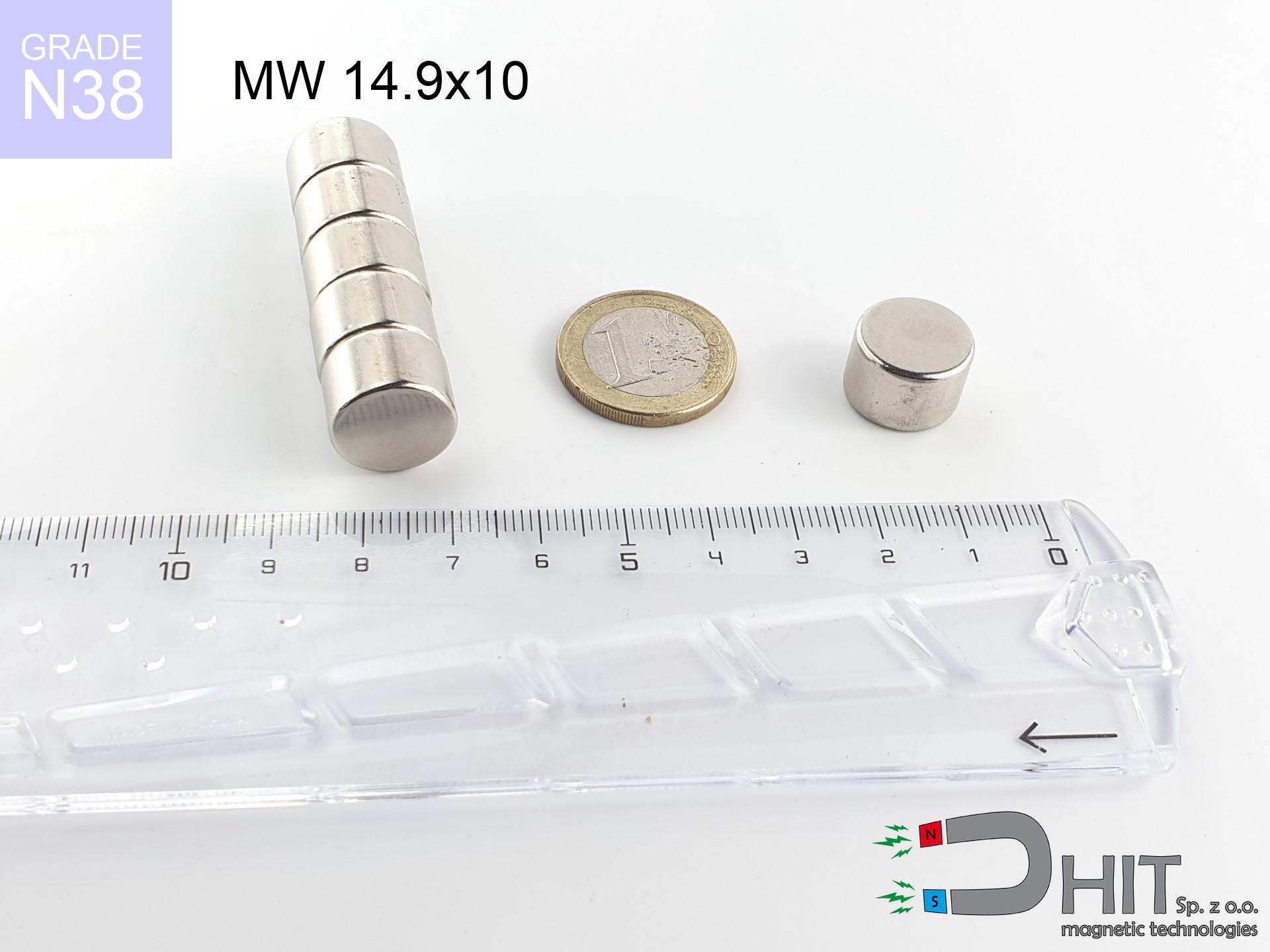
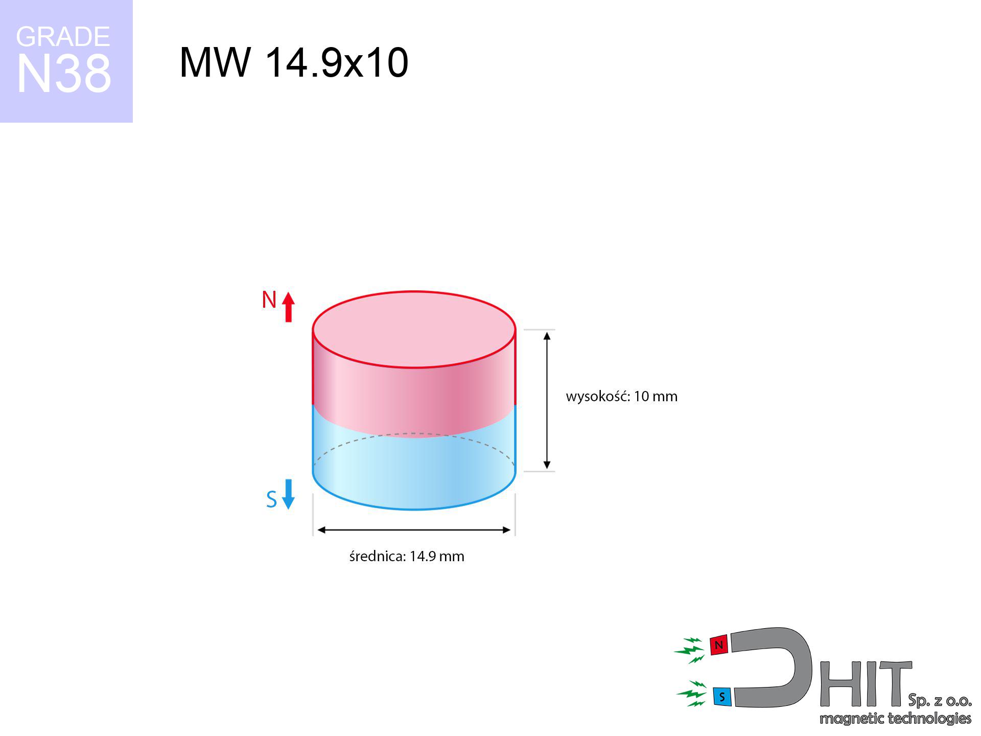
MW 14.9x10 / N38 - cylindrical magnet
cylindrical magnet
Catalog no 010023
GTIN/EAN: 5906301810223
Diameter Ø
14.9 mm [±0,1 mm]
Height
10 mm [±0,1 mm]
Weight
13.08 g
Magnetization Direction
→ diametrical
Load capacity
7.60 kg / 74.57 N
Magnetic Induction
496.78 mT / 4968 Gs
Coating
[NiCuNi] Nickel
8.24 ZŁ with VAT / pcs + price for transport
6.70 ZŁ net + 23% VAT / pcs
bulk discounts:
Need more?
Pick up the phone and ask
+48 22 499 98 98
otherwise get in touch by means of
form
our website.
Lifting power along with shape of neodymium magnets can be verified on our
our magnetic calculator.
Orders submitted before 14:00 will be dispatched today!
Technical details - MW 14.9x10 / N38 - cylindrical magnet
Specification / characteristics - MW 14.9x10 / N38 - cylindrical magnet
| properties | values |
|---|---|
| Cat. no. | 010023 |
| GTIN/EAN | 5906301810223 |
| Production/Distribution | Dhit sp. z o.o. |
| Country of origin | Poland / China / Germany |
| Customs code | 85059029 |
| Diameter Ø | 14.9 mm [±0,1 mm] |
| Height | 10 mm [±0,1 mm] |
| Weight | 13.08 g |
| Magnetization Direction | → diametrical |
| Load capacity ~ ? | 7.60 kg / 74.57 N |
| Magnetic Induction ~ ? | 496.78 mT / 4968 Gs |
| Coating | [NiCuNi] Nickel |
| Manufacturing Tolerance | ±0.1 mm |
Magnetic properties of material N38
| properties | values | units |
|---|---|---|
| remenance Br [min. - max.] ? | 12.2-12.6 | kGs |
| remenance Br [min. - max.] ? | 1220-1260 | mT |
| coercivity bHc ? | 10.8-11.5 | kOe |
| coercivity bHc ? | 860-915 | kA/m |
| actual internal force iHc | ≥ 12 | kOe |
| actual internal force iHc | ≥ 955 | kA/m |
| energy density [min. - max.] ? | 36-38 | BH max MGOe |
| energy density [min. - max.] ? | 287-303 | BH max KJ/m |
| max. temperature ? | ≤ 80 | °C |
Physical properties of sintered neodymium magnets Nd2Fe14B at 20°C
| properties | values | units |
|---|---|---|
| Vickers hardness | ≥550 | Hv |
| Density | ≥7.4 | g/cm3 |
| Curie Temperature TC | 312 - 380 | °C |
| Curie Temperature TF | 593 - 716 | °F |
| Specific resistance | 150 | μΩ⋅cm |
| Bending strength | 250 | MPa |
| Compressive strength | 1000~1100 | MPa |
| Thermal expansion parallel (∥) to orientation (M) | (3-4) x 10-6 | °C-1 |
| Thermal expansion perpendicular (⊥) to orientation (M) | -(1-3) x 10-6 | °C-1 |
| Young's modulus | 1.7 x 10⁴ | kg/mm² |
Technical modeling of the magnet - technical parameters
The following values constitute the result of a mathematical analysis. Results were calculated on algorithms for the material Nd2Fe14B. Actual performance may differ. Treat these data as a preliminary roadmap during assembly planning.
Table 1: Static force (pull vs distance) - power drop
MW 14.9x10 / N38
| Distance (mm) | Induction (Gauss) / mT | Pull Force (kg/lbs/g/N) | Risk Status |
|---|---|---|---|
| 0 mm |
4965 Gs
496.5 mT
|
7.60 kg / 16.76 lbs
7600.0 g / 74.6 N
|
medium risk |
| 1 mm |
4309 Gs
430.9 mT
|
5.72 kg / 12.62 lbs
5722.6 g / 56.1 N
|
medium risk |
| 2 mm |
3660 Gs
366.0 mT
|
4.13 kg / 9.10 lbs
4129.1 g / 40.5 N
|
medium risk |
| 3 mm |
3063 Gs
306.3 mT
|
2.89 kg / 6.38 lbs
2892.7 g / 28.4 N
|
medium risk |
| 5 mm |
2098 Gs
209.8 mT
|
1.36 kg / 2.99 lbs
1356.5 g / 13.3 N
|
low risk |
| 10 mm |
838 Gs
83.8 mT
|
0.22 kg / 0.48 lbs
216.5 g / 2.1 N
|
low risk |
| 15 mm |
389 Gs
38.9 mT
|
0.05 kg / 0.10 lbs
46.6 g / 0.5 N
|
low risk |
| 20 mm |
207 Gs
20.7 mT
|
0.01 kg / 0.03 lbs
13.2 g / 0.1 N
|
low risk |
| 30 mm |
78 Gs
7.8 mT
|
0.00 kg / 0.00 lbs
1.9 g / 0.0 N
|
low risk |
| 50 mm |
20 Gs
2.0 mT
|
0.00 kg / 0.00 lbs
0.1 g / 0.0 N
|
low risk |
Table 2: Slippage hold (vertical surface)
MW 14.9x10 / N38
| Distance (mm) | Friction coefficient | Pull Force (kg/lbs/g/N) |
|---|---|---|
| 0 mm | Stal (~0.2) |
1.52 kg / 3.35 lbs
1520.0 g / 14.9 N
|
| 1 mm | Stal (~0.2) |
1.14 kg / 2.52 lbs
1144.0 g / 11.2 N
|
| 2 mm | Stal (~0.2) |
0.83 kg / 1.82 lbs
826.0 g / 8.1 N
|
| 3 mm | Stal (~0.2) |
0.58 kg / 1.27 lbs
578.0 g / 5.7 N
|
| 5 mm | Stal (~0.2) |
0.27 kg / 0.60 lbs
272.0 g / 2.7 N
|
| 10 mm | Stal (~0.2) |
0.04 kg / 0.10 lbs
44.0 g / 0.4 N
|
| 15 mm | Stal (~0.2) |
0.01 kg / 0.02 lbs
10.0 g / 0.1 N
|
| 20 mm | Stal (~0.2) |
0.00 kg / 0.00 lbs
2.0 g / 0.0 N
|
| 30 mm | Stal (~0.2) |
0.00 kg / 0.00 lbs
0.0 g / 0.0 N
|
| 50 mm | Stal (~0.2) |
0.00 kg / 0.00 lbs
0.0 g / 0.0 N
|
Table 3: Vertical assembly (shearing) - vertical pull
MW 14.9x10 / N38
| Surface type | Friction coefficient / % Mocy | Max load (kg/lbs/g/N) |
|---|---|---|
| Raw steel |
µ = 0.3
30% Nominalnej Siły
|
2.28 kg / 5.03 lbs
2280.0 g / 22.4 N
|
| Painted steel (standard) |
µ = 0.2
20% Nominalnej Siły
|
1.52 kg / 3.35 lbs
1520.0 g / 14.9 N
|
| Oily/slippery steel |
µ = 0.1
10% Nominalnej Siły
|
0.76 kg / 1.68 lbs
760.0 g / 7.5 N
|
| Magnet with anti-slip rubber |
µ = 0.5
50% Nominalnej Siły
|
3.80 kg / 8.38 lbs
3800.0 g / 37.3 N
|
Table 4: Steel thickness (substrate influence) - sheet metal selection
MW 14.9x10 / N38
| Steel thickness (mm) | % power | Real pull force (kg/lbs/g/N) |
|---|---|---|
| 0.5 mm |
|
0.76 kg / 1.68 lbs
760.0 g / 7.5 N
|
| 1 mm |
|
1.90 kg / 4.19 lbs
1900.0 g / 18.6 N
|
| 2 mm |
|
3.80 kg / 8.38 lbs
3800.0 g / 37.3 N
|
| 3 mm |
|
5.70 kg / 12.57 lbs
5700.0 g / 55.9 N
|
| 5 mm |
|
7.60 kg / 16.76 lbs
7600.0 g / 74.6 N
|
| 10 mm |
|
7.60 kg / 16.76 lbs
7600.0 g / 74.6 N
|
| 11 mm |
|
7.60 kg / 16.76 lbs
7600.0 g / 74.6 N
|
| 12 mm |
|
7.60 kg / 16.76 lbs
7600.0 g / 74.6 N
|
Table 5: Thermal stability (stability) - power drop
MW 14.9x10 / N38
| Ambient temp. (°C) | Power loss | Remaining pull (kg/lbs/g/N) | Status |
|---|---|---|---|
| 20 °C | 0.0% |
7.60 kg / 16.76 lbs
7600.0 g / 74.6 N
|
OK |
| 40 °C | -2.2% |
7.43 kg / 16.39 lbs
7432.8 g / 72.9 N
|
OK |
| 60 °C | -4.4% |
7.27 kg / 16.02 lbs
7265.6 g / 71.3 N
|
OK |
| 80 °C | -6.6% |
7.10 kg / 15.65 lbs
7098.4 g / 69.6 N
|
|
| 100 °C | -28.8% |
5.41 kg / 11.93 lbs
5411.2 g / 53.1 N
|
Table 6: Magnet-Magnet interaction (repulsion) - field collision
MW 14.9x10 / N38
| Gap (mm) | Attraction (kg/lbs) (N-S) | Shear Force (kg/lbs/g/N) | Repulsion (kg/lbs) (N-N) |
|---|---|---|---|
| 0 mm |
26.50 kg / 58.43 lbs
5 802 Gs
|
3.98 kg / 8.76 lbs
3975 g / 39.0 N
|
N/A |
| 1 mm |
23.16 kg / 51.05 lbs
9 283 Gs
|
3.47 kg / 7.66 lbs
3474 g / 34.1 N
|
20.84 kg / 45.95 lbs
~0 Gs
|
| 2 mm |
19.96 kg / 44.00 lbs
8 617 Gs
|
2.99 kg / 6.60 lbs
2993 g / 29.4 N
|
17.96 kg / 39.60 lbs
~0 Gs
|
| 3 mm |
17.03 kg / 37.54 lbs
7 959 Gs
|
2.55 kg / 5.63 lbs
2554 g / 25.1 N
|
15.32 kg / 33.78 lbs
~0 Gs
|
| 5 mm |
12.09 kg / 26.65 lbs
6 707 Gs
|
1.81 kg / 4.00 lbs
1813 g / 17.8 N
|
10.88 kg / 23.99 lbs
~0 Gs
|
| 10 mm |
4.73 kg / 10.43 lbs
4 196 Gs
|
0.71 kg / 1.56 lbs
710 g / 7.0 N
|
4.26 kg / 9.39 lbs
~0 Gs
|
| 20 mm |
0.76 kg / 1.66 lbs
1 676 Gs
|
0.11 kg / 0.25 lbs
113 g / 1.1 N
|
0.68 kg / 1.50 lbs
~0 Gs
|
| 50 mm |
0.02 kg / 0.04 lbs
245 Gs
|
0.00 kg / 0.01 lbs
2 g / 0.0 N
|
0.01 kg / 0.03 lbs
~0 Gs
|
| 60 mm |
0.01 kg / 0.01 lbs
156 Gs
|
0.00 kg / 0.00 lbs
1 g / 0.0 N
|
0.00 kg / 0.00 lbs
~0 Gs
|
| 70 mm |
0.00 kg / 0.01 lbs
105 Gs
|
0.00 kg / 0.00 lbs
0 g / 0.0 N
|
0.00 kg / 0.00 lbs
~0 Gs
|
| 80 mm |
0.00 kg / 0.00 lbs
74 Gs
|
0.00 kg / 0.00 lbs
0 g / 0.0 N
|
0.00 kg / 0.00 lbs
~0 Gs
|
| 90 mm |
0.00 kg / 0.00 lbs
54 Gs
|
0.00 kg / 0.00 lbs
0 g / 0.0 N
|
0.00 kg / 0.00 lbs
~0 Gs
|
| 100 mm |
0.00 kg / 0.00 lbs
41 Gs
|
0.00 kg / 0.00 lbs
0 g / 0.0 N
|
0.00 kg / 0.00 lbs
~0 Gs
|
Table 7: Protective zones (implants) - warnings
MW 14.9x10 / N38
| Object / Device | Limit (Gauss) / mT | Safe distance |
|---|---|---|
| Pacemaker | 5 Gs (0.5 mT) | 8.5 cm |
| Hearing aid | 10 Gs (1.0 mT) | 6.5 cm |
| Mechanical watch | 20 Gs (2.0 mT) | 5.5 cm |
| Phone / Smartphone | 40 Gs (4.0 mT) | 4.0 cm |
| Remote | 50 Gs (5.0 mT) | 4.0 cm |
| Payment card | 400 Gs (40.0 mT) | 1.5 cm |
| HDD hard drive | 600 Gs (60.0 mT) | 1.5 cm |
Table 8: Dynamics (cracking risk) - warning
MW 14.9x10 / N38
| Start from (mm) | Speed (km/h) | Energy (J) | Predicted outcome |
|---|---|---|---|
| 10 mm |
24.74 km/h
(6.87 m/s)
|
0.31 J | |
| 30 mm |
42.11 km/h
(11.70 m/s)
|
0.89 J | |
| 50 mm |
54.36 km/h
(15.10 m/s)
|
1.49 J | |
| 100 mm |
76.87 km/h
(21.35 m/s)
|
2.98 J |
Table 9: Coating parameters (durability)
MW 14.9x10 / N38
| Technical parameter | Value / Description |
|---|---|
| Coating type | [NiCuNi] Nickel |
| Layer structure | Nickel - Copper - Nickel |
| Layer thickness | 10-20 µm |
| Salt spray test (SST) ? | 24 h |
| Recommended environment | Indoors only (dry) |
Table 10: Construction data (Pc)
MW 14.9x10 / N38
| Parameter | Value | SI Unit / Description |
|---|---|---|
| Magnetic Flux | 8 732 Mx | 87.3 µWb |
| Pc Coefficient | 0.71 | High (Stable) |
Table 11: Underwater work (magnet fishing)
MW 14.9x10 / N38
| Environment | Effective steel pull | Effect |
|---|---|---|
| Air (land) | 7.60 kg | Standard |
| Water (riverbed) |
8.70 kg
(+1.10 kg buoyancy gain)
|
+14.5% |
1. Vertical hold
*Note: On a vertical wall, the magnet holds just a fraction of its nominal pull.
2. Steel thickness impact
*Thin steel (e.g. computer case) significantly reduces the holding force.
3. Thermal stability
*For N38 material, the max working temp is 80°C.
4. Demagnetization curve and operating point (B-H)
chart generated for the permeance coefficient Pc (Permeance Coefficient) = 0.71
This simulation demonstrates the magnetic stability of the selected magnet under specific geometric conditions. The solid red line represents the demagnetization curve (material potential), while the dashed blue line is the load line based on the magnet's geometry. The Pc (Permeance Coefficient), also known as the load line slope, is a dimensionless value that describes the relationship between the magnet's shape and its magnetic stability. The intersection of these two lines (the black dot) is the operating point — it determines the actual magnetic flux density generated by the magnet in this specific configuration. A higher Pc value means the magnet is more 'slender' (tall relative to its area), resulting in a higher operating point and better resistance to irreversible demagnetization caused by external fields or temperature. A value of 0.42 is relatively low (typical for flat magnets), meaning the operating point is closer to the 'knee' of the curve — caution is advised when operating at temperatures near the maximum limit to avoid strength loss.
Elemental analysis
| iron (Fe) | 64% – 68% |
| neodymium (Nd) | 29% – 32% |
| boron (B) | 1.1% – 1.2% |
| dysprosium (Dy) | 0.5% – 2.0% |
| coating (Ni-Cu-Ni) | < 0.05% |
Ecology and recycling (GPSR)
| recyclability (EoL) | 100% |
| recycled raw materials | ~10% (pre-cons) |
| carbon footprint | low / zredukowany |
| waste code (EWC) | 16 02 16 |
Other proposals


Strengths as well as weaknesses of neodymium magnets.
Advantages
- They retain magnetic properties for nearly 10 years – the loss is just ~1% (in theory),
- Magnets very well protect themselves against loss of magnetization caused by ambient magnetic noise,
- In other words, due to the glossy surface of gold, the element looks attractive,
- Magnetic induction on the top side of the magnet is exceptional,
- Due to their durability and thermal resistance, neodymium magnets can operate (depending on the shape) even at high temperatures reaching 230°C or more...
- Thanks to modularity in constructing and the capacity to modify to client solutions,
- Universal use in innovative solutions – they are commonly used in HDD drives, electric drive systems, precision medical tools, and complex engineering applications.
- Compactness – despite small sizes they generate large force, making them ideal for precision applications
Weaknesses
- They are prone to damage upon heavy impacts. To avoid cracks, it is worth securing magnets in a protective case. Such protection not only shields the magnet but also improves its resistance to damage
- Neodymium magnets decrease their strength under the influence of heating. As soon as 80°C is exceeded, many of them start losing their power. Therefore, we recommend our special magnets marked [AH], which maintain stability even at temperatures up to 230°C
- They oxidize in a humid environment. For use outdoors we recommend using waterproof magnets e.g. in rubber, plastic
- Due to limitations in producing nuts and complicated forms in magnets, we recommend using a housing - magnetic mechanism.
- Health risk resulting from small fragments of magnets can be dangerous, when accidentally swallowed, which becomes key in the context of child health protection. Additionally, small elements of these devices are able to complicate diagnosis medical when they are in the body.
- Due to expensive raw materials, their price exceeds standard values,
Pull force analysis
Maximum magnetic pulling force – what it depends on?
- using a sheet made of mild steel, serving as a circuit closing element
- possessing a massiveness of at least 10 mm to ensure full flux closure
- with an polished touching surface
- without any clearance between the magnet and steel
- for force acting at a right angle (pull-off, not shear)
- at temperature approx. 20 degrees Celsius
Practical lifting capacity: influencing factors
- Distance (betwixt the magnet and the plate), since even a very small distance (e.g. 0.5 mm) leads to a drastic drop in lifting capacity by up to 50% (this also applies to varnish, corrosion or dirt).
- Force direction – declared lifting capacity refers to pulling vertically. When attempting to slide, the magnet exhibits much less (often approx. 20-30% of maximum force).
- Substrate thickness – for full efficiency, the steel must be adequately massive. Thin sheet restricts the attraction force (the magnet "punches through" it).
- Material type – ideal substrate is pure iron steel. Cast iron may generate lower lifting capacity.
- Smoothness – full contact is obtained only on polished steel. Rough texture reduce the real contact area, reducing force.
- Temperature – heating the magnet results in weakening of force. It is worth remembering the maximum operating temperature for a given model.
Lifting capacity was assessed using a smooth steel plate of suitable thickness (min. 20 mm), under perpendicular pulling force, however under parallel forces the lifting capacity is smaller. In addition, even a small distance between the magnet and the plate lowers the holding force.
Precautions when working with neodymium magnets
Respect the power
Before use, check safety instructions. Uncontrolled attraction can destroy the magnet or injure your hand. Think ahead.
Serious injuries
Big blocks can crush fingers in a fraction of a second. Never put your hand betwixt two strong magnets.
Shattering risk
Despite metallic appearance, neodymium is brittle and cannot withstand shocks. Avoid impacts, as the magnet may shatter into sharp, dangerous pieces.
Nickel coating and allergies
Warning for allergy sufferers: The Ni-Cu-Ni coating contains nickel. If redness appears, immediately stop handling magnets and wear gloves.
Permanent damage
Standard neodymium magnets (grade N) undergo demagnetization when the temperature exceeds 80°C. This process is irreversible.
Choking Hazard
Adult use only. Small elements pose a choking risk, causing intestinal necrosis. Keep out of reach of children and animals.
Fire warning
Powder generated during machining of magnets is self-igniting. Do not drill into magnets without proper cooling and knowledge.
Health Danger
Warning for patients: Strong magnetic fields disrupt electronics. Keep minimum 30 cm distance or ask another person to work with the magnets.
GPS Danger
A powerful magnetic field negatively affects the functioning of compasses in phones and GPS navigation. Do not bring magnets close to a device to prevent breaking the sensors.
Data carriers
Avoid bringing magnets near a wallet, computer, or TV. The magnetism can permanently damage these devices and erase data from cards.
Tabela kosztu i czasu dostawy
Płatność przed wysyłką:

GLS kurier
Przesyłka będzie u Ciebie za 2-3 dni
14.99 ZŁ

InPost Paczkomaty 24/7
Przesyłka będzie u Ciebie za 1-2 dni
12.30 ZŁ
Płatność przy odbiorze (pobranie):
GLS kurier
Przesyłka będzie u Ciebie za 1-2 dni
23.00 ZŁ
Rate the product
Your rating