
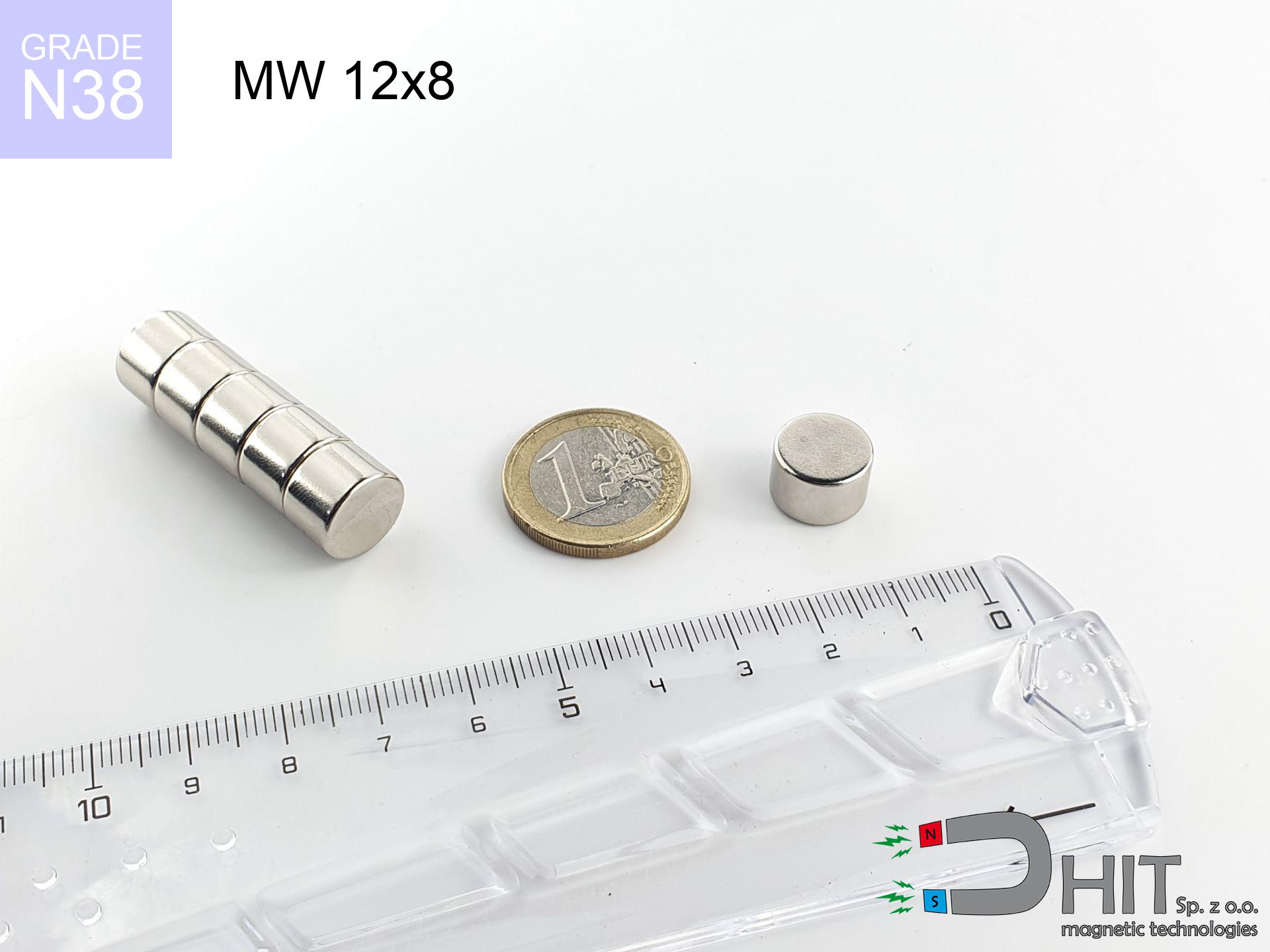
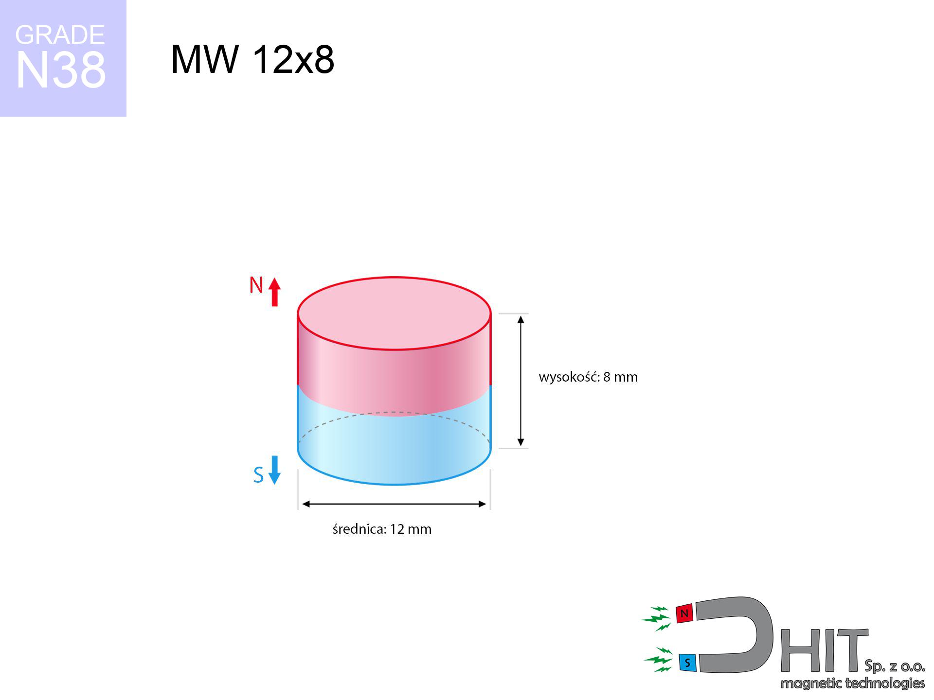
MW 12x8 / N38 - cylindrical magnet
cylindrical magnet
Catalog no 010022
GTIN/EAN: 5906301810216
Diameter Ø
12 mm [±0,1 mm]
Height
8 mm [±0,1 mm]
Weight
6.79 g
Magnetization Direction
↑ axial
Load capacity
4.93 kg / 48.32 N
Magnetic Induction
495.50 mT / 4955 Gs
Coating
[NiCuNi] Nickel
2.47 ZŁ with VAT / pcs + price for transport
2.01 ZŁ net + 23% VAT / pcs
bulk discounts:
Need more?
Call us now
+48 888 99 98 98
or get in touch via
request form
the contact section.
Parameters along with form of magnets can be analyzed with our
power calculator.
Same-day shipping for orders placed before 14:00.
Technical details - MW 12x8 / N38 - cylindrical magnet
Specification / characteristics - MW 12x8 / N38 - cylindrical magnet
| properties | values |
|---|---|
| Cat. no. | 010022 |
| GTIN/EAN | 5906301810216 |
| Production/Distribution | Dhit sp. z o.o. |
| Country of origin | Poland / China / Germany |
| Customs code | 85059029 |
| Diameter Ø | 12 mm [±0,1 mm] |
| Height | 8 mm [±0,1 mm] |
| Weight | 6.79 g |
| Magnetization Direction | ↑ axial |
| Load capacity ~ ? | 4.93 kg / 48.32 N |
| Magnetic Induction ~ ? | 495.50 mT / 4955 Gs |
| Coating | [NiCuNi] Nickel |
| Manufacturing Tolerance | ±0.1 mm |
Magnetic properties of material N38
| properties | values | units |
|---|---|---|
| remenance Br [min. - max.] ? | 12.2-12.6 | kGs |
| remenance Br [min. - max.] ? | 1220-1260 | mT |
| coercivity bHc ? | 10.8-11.5 | kOe |
| coercivity bHc ? | 860-915 | kA/m |
| actual internal force iHc | ≥ 12 | kOe |
| actual internal force iHc | ≥ 955 | kA/m |
| energy density [min. - max.] ? | 36-38 | BH max MGOe |
| energy density [min. - max.] ? | 287-303 | BH max KJ/m |
| max. temperature ? | ≤ 80 | °C |
Physical properties of sintered neodymium magnets Nd2Fe14B at 20°C
| properties | values | units |
|---|---|---|
| Vickers hardness | ≥550 | Hv |
| Density | ≥7.4 | g/cm3 |
| Curie Temperature TC | 312 - 380 | °C |
| Curie Temperature TF | 593 - 716 | °F |
| Specific resistance | 150 | μΩ⋅cm |
| Bending strength | 250 | MPa |
| Compressive strength | 1000~1100 | MPa |
| Thermal expansion parallel (∥) to orientation (M) | (3-4) x 10-6 | °C-1 |
| Thermal expansion perpendicular (⊥) to orientation (M) | -(1-3) x 10-6 | °C-1 |
| Young's modulus | 1.7 x 10⁴ | kg/mm² |
Physical modeling of the magnet - data
These values are the result of a physical analysis. Values were calculated on models for the class Nd2Fe14B. Real-world performance might slightly differ from theoretical values. Use these data as a supplementary guide for designers.
Table 1: Static pull force (force vs gap) - interaction chart
MW 12x8 / N38
| Distance (mm) | Induction (Gauss) / mT | Pull Force (kg/lbs/g/N) | Risk Status |
|---|---|---|---|
| 0 mm |
4952 Gs
495.2 mT
|
4.93 kg / 10.87 pounds
4930.0 g / 48.4 N
|
warning |
| 1 mm |
4139 Gs
413.9 mT
|
3.44 kg / 7.59 pounds
3445.0 g / 33.8 N
|
warning |
| 2 mm |
3356 Gs
335.6 mT
|
2.26 kg / 4.99 pounds
2264.2 g / 22.2 N
|
warning |
| 3 mm |
2670 Gs
267.0 mT
|
1.43 kg / 3.16 pounds
1433.5 g / 14.1 N
|
low risk |
| 5 mm |
1660 Gs
166.0 mT
|
0.55 kg / 1.22 pounds
554.1 g / 5.4 N
|
low risk |
| 10 mm |
565 Gs
56.5 mT
|
0.06 kg / 0.14 pounds
64.3 g / 0.6 N
|
low risk |
| 15 mm |
243 Gs
24.3 mT
|
0.01 kg / 0.03 pounds
11.8 g / 0.1 N
|
low risk |
| 20 mm |
124 Gs
12.4 mT
|
0.00 kg / 0.01 pounds
3.1 g / 0.0 N
|
low risk |
| 30 mm |
45 Gs
4.5 mT
|
0.00 kg / 0.00 pounds
0.4 g / 0.0 N
|
low risk |
| 50 mm |
11 Gs
1.1 mT
|
0.00 kg / 0.00 pounds
0.0 g / 0.0 N
|
low risk |
Table 2: Shear capacity (vertical surface)
MW 12x8 / N38
| Distance (mm) | Friction coefficient | Pull Force (kg/lbs/g/N) |
|---|---|---|
| 0 mm | Stal (~0.2) |
0.99 kg / 2.17 pounds
986.0 g / 9.7 N
|
| 1 mm | Stal (~0.2) |
0.69 kg / 1.52 pounds
688.0 g / 6.7 N
|
| 2 mm | Stal (~0.2) |
0.45 kg / 1.00 pounds
452.0 g / 4.4 N
|
| 3 mm | Stal (~0.2) |
0.29 kg / 0.63 pounds
286.0 g / 2.8 N
|
| 5 mm | Stal (~0.2) |
0.11 kg / 0.24 pounds
110.0 g / 1.1 N
|
| 10 mm | Stal (~0.2) |
0.01 kg / 0.03 pounds
12.0 g / 0.1 N
|
| 15 mm | Stal (~0.2) |
0.00 kg / 0.00 pounds
2.0 g / 0.0 N
|
| 20 mm | Stal (~0.2) |
0.00 kg / 0.00 pounds
0.0 g / 0.0 N
|
| 30 mm | Stal (~0.2) |
0.00 kg / 0.00 pounds
0.0 g / 0.0 N
|
| 50 mm | Stal (~0.2) |
0.00 kg / 0.00 pounds
0.0 g / 0.0 N
|
Table 3: Vertical assembly (shearing) - behavior on slippery surfaces
MW 12x8 / N38
| Surface type | Friction coefficient / % Mocy | Max load (kg/lbs/g/N) |
|---|---|---|
| Raw steel |
µ = 0.3
30% Nominalnej Siły
|
1.48 kg / 3.26 pounds
1479.0 g / 14.5 N
|
| Painted steel (standard) |
µ = 0.2
20% Nominalnej Siły
|
0.99 kg / 2.17 pounds
986.0 g / 9.7 N
|
| Oily/slippery steel |
µ = 0.1
10% Nominalnej Siły
|
0.49 kg / 1.09 pounds
493.0 g / 4.8 N
|
| Magnet with anti-slip rubber |
µ = 0.5
50% Nominalnej Siły
|
2.47 kg / 5.43 pounds
2465.0 g / 24.2 N
|
Table 4: Steel thickness (substrate influence) - sheet metal selection
MW 12x8 / N38
| Steel thickness (mm) | % power | Real pull force (kg/lbs/g/N) |
|---|---|---|
| 0.5 mm |
|
0.49 kg / 1.09 pounds
493.0 g / 4.8 N
|
| 1 mm |
|
1.23 kg / 2.72 pounds
1232.5 g / 12.1 N
|
| 2 mm |
|
2.47 kg / 5.43 pounds
2465.0 g / 24.2 N
|
| 3 mm |
|
3.70 kg / 8.15 pounds
3697.5 g / 36.3 N
|
| 5 mm |
|
4.93 kg / 10.87 pounds
4930.0 g / 48.4 N
|
| 10 mm |
|
4.93 kg / 10.87 pounds
4930.0 g / 48.4 N
|
| 11 mm |
|
4.93 kg / 10.87 pounds
4930.0 g / 48.4 N
|
| 12 mm |
|
4.93 kg / 10.87 pounds
4930.0 g / 48.4 N
|
Table 5: Thermal stability (stability) - power drop
MW 12x8 / N38
| Ambient temp. (°C) | Power loss | Remaining pull (kg/lbs/g/N) | Status |
|---|---|---|---|
| 20 °C | 0.0% |
4.93 kg / 10.87 pounds
4930.0 g / 48.4 N
|
OK |
| 40 °C | -2.2% |
4.82 kg / 10.63 pounds
4821.5 g / 47.3 N
|
OK |
| 60 °C | -4.4% |
4.71 kg / 10.39 pounds
4713.1 g / 46.2 N
|
OK |
| 80 °C | -6.6% |
4.60 kg / 10.15 pounds
4604.6 g / 45.2 N
|
|
| 100 °C | -28.8% |
3.51 kg / 7.74 pounds
3510.2 g / 34.4 N
|
Table 6: Magnet-Magnet interaction (repulsion) - field collision
MW 12x8 / N38
| Gap (mm) | Attraction (kg/lbs) (N-S) | Lateral Force (kg/lbs/g/N) | Repulsion (kg/lbs) (N-N) |
|---|---|---|---|
| 0 mm |
17.10 kg / 37.69 pounds
5 795 Gs
|
2.56 kg / 5.65 pounds
2565 g / 25.2 N
|
N/A |
| 1 mm |
14.44 kg / 31.83 pounds
9 101 Gs
|
2.17 kg / 4.77 pounds
2166 g / 21.2 N
|
12.99 kg / 28.64 pounds
~0 Gs
|
| 2 mm |
11.95 kg / 26.34 pounds
8 279 Gs
|
1.79 kg / 3.95 pounds
1792 g / 17.6 N
|
10.75 kg / 23.71 pounds
~0 Gs
|
| 3 mm |
9.74 kg / 21.48 pounds
7 477 Gs
|
1.46 kg / 3.22 pounds
1462 g / 14.3 N
|
8.77 kg / 19.33 pounds
~0 Gs
|
| 5 mm |
6.27 kg / 13.82 pounds
5 997 Gs
|
0.94 kg / 2.07 pounds
940 g / 9.2 N
|
5.64 kg / 12.44 pounds
~0 Gs
|
| 10 mm |
1.92 kg / 4.24 pounds
3 320 Gs
|
0.29 kg / 0.64 pounds
288 g / 2.8 N
|
1.73 kg / 3.81 pounds
~0 Gs
|
| 20 mm |
0.22 kg / 0.49 pounds
1 131 Gs
|
0.03 kg / 0.07 pounds
33 g / 0.3 N
|
0.20 kg / 0.44 pounds
~0 Gs
|
| 50 mm |
0.00 kg / 0.01 pounds
142 Gs
|
0.00 kg / 0.00 pounds
1 g / 0.0 N
|
0.00 kg / 0.00 pounds
~0 Gs
|
| 60 mm |
0.00 kg / 0.00 pounds
89 Gs
|
0.00 kg / 0.00 pounds
0 g / 0.0 N
|
0.00 kg / 0.00 pounds
~0 Gs
|
| 70 mm |
0.00 kg / 0.00 pounds
59 Gs
|
0.00 kg / 0.00 pounds
0 g / 0.0 N
|
0.00 kg / 0.00 pounds
~0 Gs
|
| 80 mm |
0.00 kg / 0.00 pounds
41 Gs
|
0.00 kg / 0.00 pounds
0 g / 0.0 N
|
0.00 kg / 0.00 pounds
~0 Gs
|
| 90 mm |
0.00 kg / 0.00 pounds
30 Gs
|
0.00 kg / 0.00 pounds
0 g / 0.0 N
|
0.00 kg / 0.00 pounds
~0 Gs
|
| 100 mm |
0.00 kg / 0.00 pounds
23 Gs
|
0.00 kg / 0.00 pounds
0 g / 0.0 N
|
0.00 kg / 0.00 pounds
~0 Gs
|
Table 7: Hazards (electronics) - warnings
MW 12x8 / N38
| Object / Device | Limit (Gauss) / mT | Safe distance |
|---|---|---|
| Pacemaker | 5 Gs (0.5 mT) | 7.0 cm |
| Hearing aid | 10 Gs (1.0 mT) | 5.5 cm |
| Mechanical watch | 20 Gs (2.0 mT) | 4.5 cm |
| Mobile device | 40 Gs (4.0 mT) | 3.5 cm |
| Car key | 50 Gs (5.0 mT) | 3.0 cm |
| Payment card | 400 Gs (40.0 mT) | 1.5 cm |
| HDD hard drive | 600 Gs (60.0 mT) | 1.0 cm |
Table 8: Dynamics (cracking risk) - warning
MW 12x8 / N38
| Start from (mm) | Speed (km/h) | Energy (J) | Predicted outcome |
|---|---|---|---|
| 10 mm |
27.40 km/h
(7.61 m/s)
|
0.20 J | |
| 30 mm |
47.07 km/h
(13.08 m/s)
|
0.58 J | |
| 50 mm |
60.77 km/h
(16.88 m/s)
|
0.97 J | |
| 100 mm |
85.94 km/h
(23.87 m/s)
|
1.93 J |
Table 9: Anti-corrosion coating durability
MW 12x8 / N38
| Technical parameter | Value / Description |
|---|---|
| Coating type | [NiCuNi] Nickel |
| Layer structure | Nickel - Copper - Nickel |
| Layer thickness | 10-20 µm |
| Salt spray test (SST) ? | 24 h |
| Recommended environment | Indoors only (dry) |
Table 10: Electrical data (Pc)
MW 12x8 / N38
| Parameter | Value | SI Unit / Description |
|---|---|---|
| Magnetic Flux | 5 650 Mx | 56.5 µWb |
| Pc Coefficient | 0.71 | High (Stable) |
Table 11: Submerged application
MW 12x8 / N38
| Environment | Effective steel pull | Effect |
|---|---|---|
| Air (land) | 4.93 kg | Standard |
| Water (riverbed) |
5.64 kg
(+0.71 kg buoyancy gain)
|
+14.5% |
1. Shear force
*Warning: On a vertical wall, the magnet holds merely ~20% of its nominal pull.
2. Steel saturation
*Thin steel (e.g. computer case) severely reduces the holding force.
3. Heat tolerance
*For standard magnets, the critical limit is 80°C.
4. Demagnetization curve and operating point (B-H)
chart generated for the permeance coefficient Pc (Permeance Coefficient) = 0.71
The chart above illustrates the magnetic characteristics of the material within the second quadrant of the hysteresis loop. The solid red line represents the demagnetization curve (material potential), while the dashed blue line is the load line based on the magnet's geometry. The Pc (Permeance Coefficient), also known as the load line slope, is a dimensionless value that describes the relationship between the magnet's shape and its magnetic stability. The intersection of these two lines (the black dot) is the operating point — it determines the actual magnetic flux density generated by the magnet in this specific configuration. A higher Pc value means the magnet is more 'slender' (tall relative to its area), resulting in a higher operating point and better resistance to irreversible demagnetization caused by external fields or temperature. A value of 0.42 is relatively low (typical for flat magnets), meaning the operating point is closer to the 'knee' of the curve — caution is advised when operating at temperatures near the maximum limit to avoid strength loss.
Material specification
| iron (Fe) | 64% – 68% |
| neodymium (Nd) | 29% – 32% |
| boron (B) | 1.1% – 1.2% |
| dysprosium (Dy) | 0.5% – 2.0% |
| coating (Ni-Cu-Ni) | < 0.05% |
Sustainability
| recyclability (EoL) | 100% |
| recycled raw materials | ~10% (pre-cons) |
| carbon footprint | low / zredukowany |
| waste code (EWC) | 16 02 16 |
Other products


Advantages and disadvantages of rare earth magnets.
Advantages
- Their power is durable, and after approximately ten years it drops only by ~1% (according to research),
- Magnets perfectly protect themselves against loss of magnetization caused by foreign field sources,
- A magnet with a shiny gold surface is more attractive,
- The surface of neodymium magnets generates a strong magnetic field – this is a key feature,
- Made from properly selected components, these magnets show impressive resistance to high heat, enabling them to function (depending on their shape) at temperatures up to 230°C and above...
- Possibility of detailed forming and optimizing to specific needs,
- Universal use in electronics industry – they are utilized in computer drives, electromotive mechanisms, diagnostic systems, as well as multitasking production systems.
- Relatively small size with high pulling force – neodymium magnets offer high power in compact dimensions, which allows their use in compact constructions
Cons
- Susceptibility to cracking is one of their disadvantages. Upon intense impact they can fracture. We advise keeping them in a special holder, which not only protects them against impacts but also raises their durability
- Neodymium magnets demagnetize when exposed to high temperatures. After reaching 80°C, many of them experience permanent drop of power (a factor is the shape and dimensions of the magnet). We offer magnets specially adapted to work at temperatures up to 230°C marked [AH], which are extremely resistant to heat
- Magnets exposed to a humid environment can corrode. Therefore when using outdoors, we advise using water-impermeable magnets made of rubber, plastic or other material protecting against moisture
- Due to limitations in realizing threads and complex shapes in magnets, we propose using a housing - magnetic holder.
- Health risk related to microscopic parts of magnets are risky, in case of ingestion, which is particularly important in the aspect of protecting the youngest. Additionally, small elements of these products are able to complicate diagnosis medical after entering the body.
- Due to neodymium price, their price is higher than average,
Lifting parameters
Detachment force of the magnet in optimal conditions – what affects it?
- using a sheet made of low-carbon steel, serving as a magnetic yoke
- with a thickness no less than 10 mm
- characterized by lack of roughness
- under conditions of no distance (surface-to-surface)
- for force acting at a right angle (in the magnet axis)
- at ambient temperature room level
Impact of factors on magnetic holding capacity in practice
- Gap between magnet and steel – every millimeter of separation (caused e.g. by veneer or unevenness) diminishes the pulling force, often by half at just 0.5 mm.
- Direction of force – maximum parameter is obtained only during perpendicular pulling. The force required to slide of the magnet along the surface is standardly several times lower (approx. 1/5 of the lifting capacity).
- Base massiveness – too thin sheet does not close the flux, causing part of the flux to be wasted into the air.
- Chemical composition of the base – mild steel attracts best. Higher carbon content decrease magnetic permeability and lifting capacity.
- Surface structure – the more even the surface, the better the adhesion and stronger the hold. Roughness acts like micro-gaps.
- Operating temperature – neodymium magnets have a sensitivity to temperature. When it is hot they are weaker, and at low temperatures they can be stronger (up to a certain limit).
Holding force was measured on the plate surface of 20 mm thickness, when a perpendicular force was applied, however under shearing force the load capacity is reduced by as much as 75%. Additionally, even a minimal clearance between the magnet and the plate reduces the lifting capacity.
H&S for magnets
Warning for allergy sufferers
Certain individuals suffer from a hypersensitivity to nickel, which is the typical protective layer for neodymium magnets. Prolonged contact might lead to a rash. We suggest use safety gloves.
Protective goggles
Watch out for shards. Magnets can fracture upon uncontrolled impact, ejecting shards into the air. Wear goggles.
Fire warning
Dust created during grinding of magnets is self-igniting. Avoid drilling into magnets without proper cooling and knowledge.
Protect data
Data protection: Strong magnets can ruin payment cards and sensitive devices (heart implants, medical aids, mechanical watches).
Do not give to children
These products are not intended for children. Swallowing a few magnets may result in them pinching intestinal walls, which constitutes a critical condition and requires urgent medical intervention.
Crushing force
Risk of injury: The pulling power is so immense that it can result in hematomas, crushing, and broken bones. Protective gloves are recommended.
Danger to pacemakers
Medical warning: Strong magnets can turn off heart devices and defibrillators. Stay away if you have medical devices.
Heat sensitivity
Regular neodymium magnets (N-type) lose magnetization when the temperature exceeds 80°C. This process is irreversible.
Handling rules
Exercise caution. Neodymium magnets act from a long distance and snap with massive power, often quicker than you can react.
Magnetic interference
An intense magnetic field disrupts the functioning of magnetometers in smartphones and navigation systems. Maintain magnets close to a device to prevent damaging the sensors.
Tabela kosztu i czasu dostawy
Płatność przed wysyłką:

GLS kurier
Przesyłka będzie u Ciebie za 2-3 dni
14.99 ZŁ

InPost Paczkomaty 24/7
Przesyłka będzie u Ciebie za 1-2 dni
12.30 ZŁ
Płatność przy odbiorze (pobranie):
GLS kurier
Przesyłka będzie u Ciebie za 1-2 dni
23.00 ZŁ
Rate the product
Your rating