
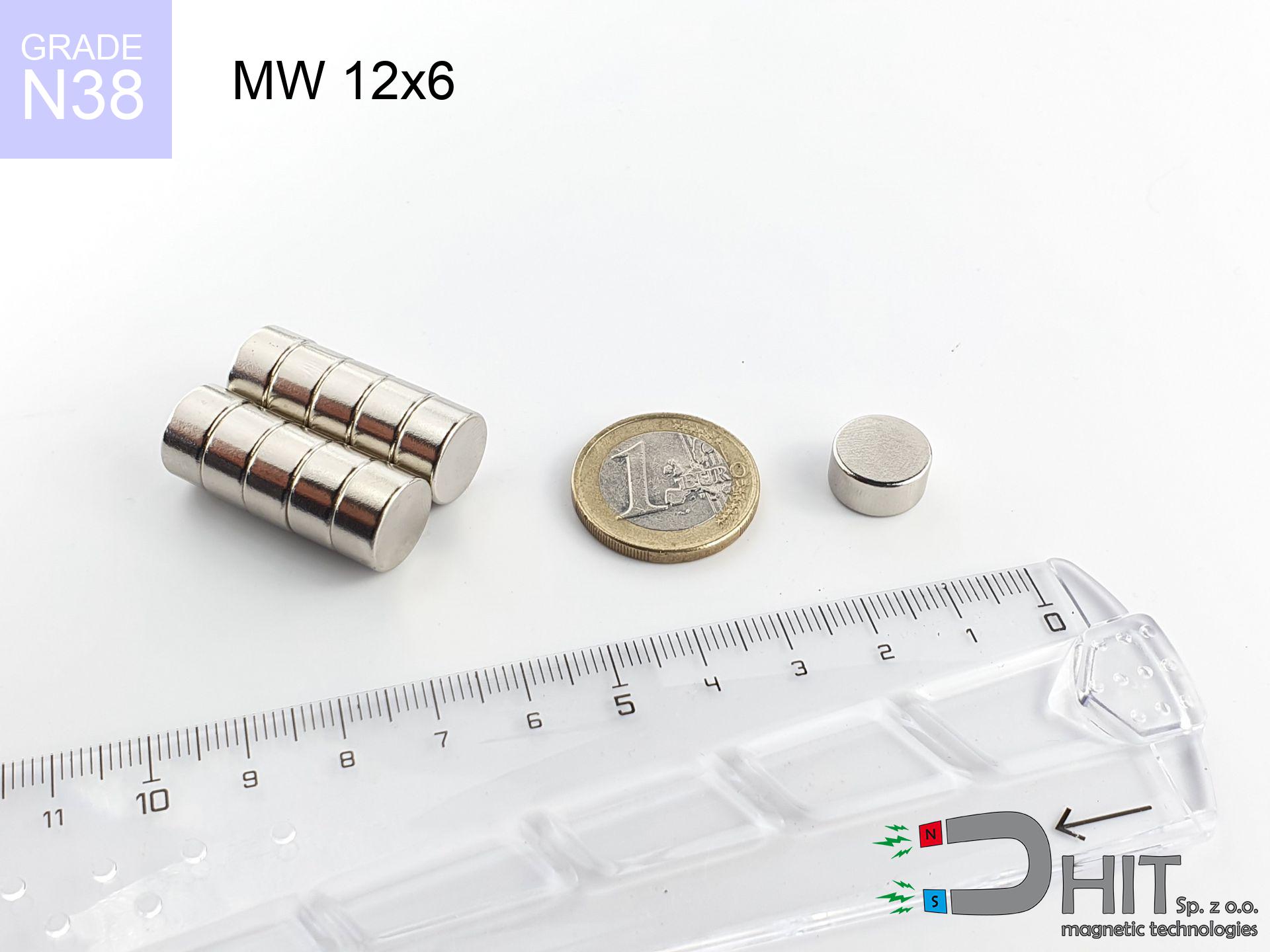
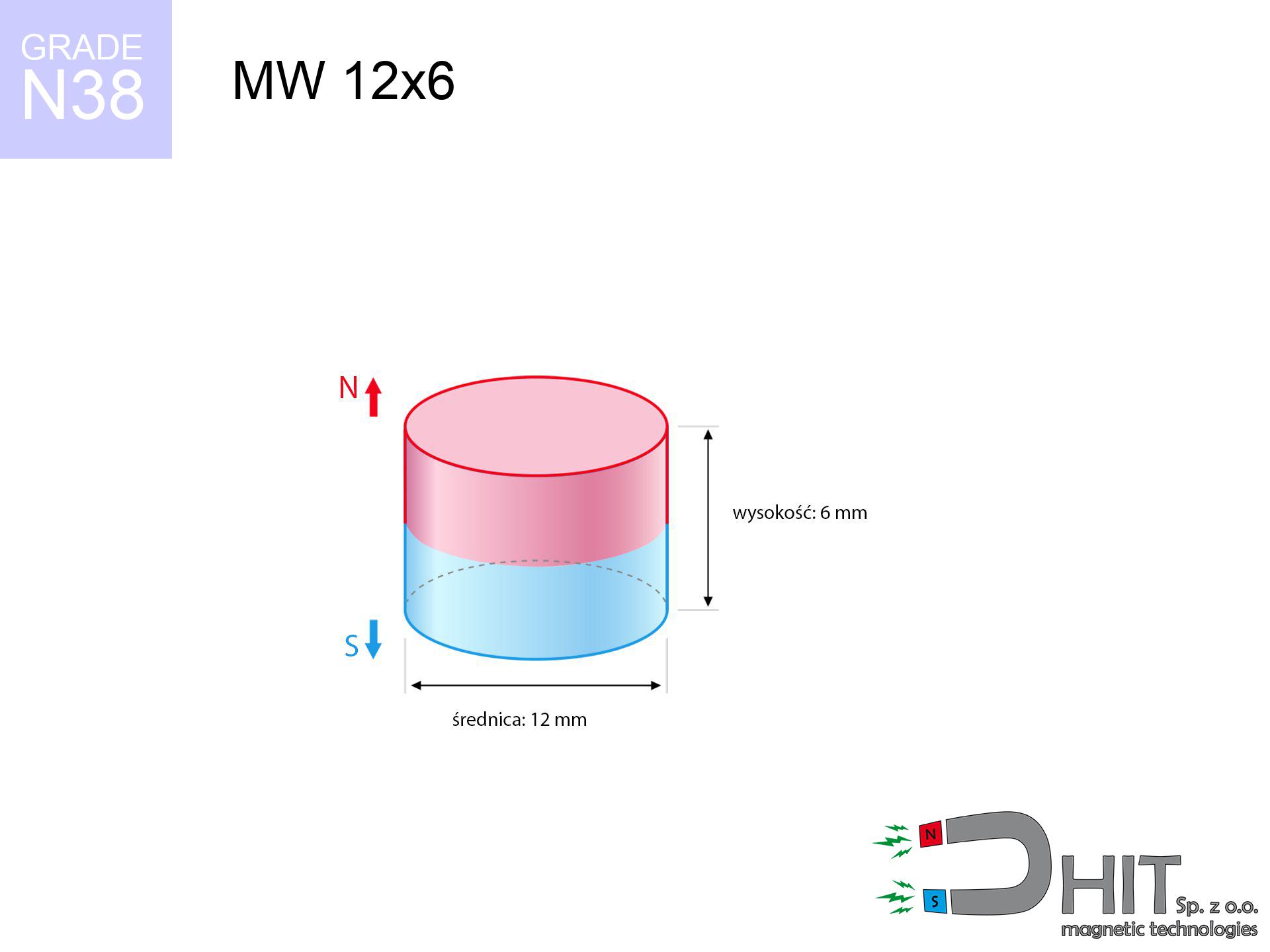
MW 12x6 / N38 - cylindrical magnet
cylindrical magnet
Catalog no 010021
GTIN/EAN: 5906301810209
Diameter Ø
12 mm [±0,1 mm]
Height
6 mm [±0,1 mm]
Weight
5.09 g
Magnetization Direction
↑ axial
Load capacity
4.60 kg / 45.09 N
Magnetic Induction
437.99 mT / 4380 Gs
Coating
[NiCuNi] Nickel
1.882 ZŁ with VAT / pcs + price for transport
1.530 ZŁ net + 23% VAT / pcs
bulk discounts:
Need more?Engineering report for this magnet
Full PDF analysis: pull and shear force, effect of distance, temperature and plate thickness, safety distances and the demagnetization curve.
Pick up the phone and ask
+48 22 499 98 98
or get in touch using
contact form
the contact form page.
Lifting power along with appearance of magnetic components can be tested on our
magnetic mass calculator.
Orders placed before 14:00 will be shipped the same business day.
Detailed specification - MW 12x6 / N38 - cylindrical magnet
Specification / characteristics - MW 12x6 / N38 - cylindrical magnet
| properties | values |
|---|---|
| Cat. no. | 010021 |
| GTIN/EAN | 5906301810209 |
| Production/Distribution | Dhit sp. z o.o. |
| Country of origin | Poland / China / Germany |
| Customs code | 85059029 |
| Diameter Ø | 12 mm [±0,1 mm] |
| Height | 6 mm [±0,1 mm] |
| Weight | 5.09 g |
| Magnetization Direction | ↑ axial |
| Load capacity ~ ? | 4.60 kg / 45.09 N |
| Magnetic Induction ~ ? | 437.99 mT / 4380 Gs |
| Coating | [NiCuNi] Nickel |
| Manufacturing Tolerance | ±0.1 mm |
Magnetic properties of material N38
| properties | values | units |
|---|---|---|
| remenance Br [min. - max.] ? | 12.2-12.6 | kGs |
| remenance Br [min. - max.] ? | 1220-1260 | mT |
| coercivity bHc ? | 10.8-11.5 | kOe |
| coercivity bHc ? | 860-915 | kA/m |
| actual internal force iHc | ≥ 12 | kOe |
| actual internal force iHc | ≥ 955 | kA/m |
| energy density [min. - max.] ? | 36-38 | BH max MGOe |
| energy density [min. - max.] ? | 287-303 | BH max KJ/m |
| max. temperature ? | ≤ 80 | °C |
Physical properties of sintered neodymium magnets Nd2Fe14B at 20°C
| properties | values | units |
|---|---|---|
| Vickers hardness | ≥550 | Hv |
| Density | ≥7.4 | g/cm3 |
| Curie Temperature TC | 312 - 380 | °C |
| Curie Temperature TF | 593 - 716 | °F |
| Specific resistance | 150 | μΩ⋅cm |
| Bending strength | 250 | MPa |
| Compressive strength | 1000~1100 | MPa |
| Thermal expansion parallel (∥) to orientation (M) | (3-4) x 10-6 | °C-1 |
| Thermal expansion perpendicular (⊥) to orientation (M) | -(1-3) x 10-6 | °C-1 |
| Young's modulus | 1.7 x 10⁴ | kg/mm² |
Engineering simulation of the assembly - technical parameters
The following information represent the direct effect of a physical simulation. Values rely on algorithms for the class Nd2Fe14B. Actual performance may differ. Use these calculations as a supplementary guide when designing systems.
Table 1: Static force (pull vs distance) - characteristics
MW 12x6 / N38
| Distance (mm) | Induction (Gauss) / mT | Pull Force (kg/lbs/g/N) | Risk Status |
|---|---|---|---|
| 0 mm |
4377 Gs
437.7 mT
|
4.60 kg / 10.14 lbs
4600.0 g / 45.1 N
|
warning |
| 1 mm |
3688 Gs
368.8 mT
|
3.27 kg / 7.20 lbs
3265.4 g / 32.0 N
|
warning |
| 2 mm |
2999 Gs
299.9 mT
|
2.16 kg / 4.76 lbs
2159.7 g / 21.2 N
|
warning |
| 3 mm |
2386 Gs
238.6 mT
|
1.37 kg / 3.01 lbs
1366.7 g / 13.4 N
|
weak grip |
| 5 mm |
1474 Gs
147.4 mT
|
0.52 kg / 1.15 lbs
521.4 g / 5.1 N
|
weak grip |
| 10 mm |
489 Gs
48.9 mT
|
0.06 kg / 0.13 lbs
57.4 g / 0.6 N
|
weak grip |
| 15 mm |
205 Gs
20.5 mT
|
0.01 kg / 0.02 lbs
10.1 g / 0.1 N
|
weak grip |
| 20 mm |
103 Gs
10.3 mT
|
0.00 kg / 0.01 lbs
2.5 g / 0.0 N
|
weak grip |
| 30 mm |
36 Gs
3.6 mT
|
0.00 kg / 0.00 lbs
0.3 g / 0.0 N
|
weak grip |
| 50 mm |
9 Gs
0.9 mT
|
0.00 kg / 0.00 lbs
0.0 g / 0.0 N
|
weak grip |
Table 2: Slippage capacity (wall)
MW 12x6 / N38
| Distance (mm) | Friction coefficient | Pull Force (kg/lbs/g/N) |
|---|---|---|
| 0 mm | Stal (~0.2) |
0.92 kg / 2.03 lbs
920.0 g / 9.0 N
|
| 1 mm | Stal (~0.2) |
0.65 kg / 1.44 lbs
654.0 g / 6.4 N
|
| 2 mm | Stal (~0.2) |
0.43 kg / 0.95 lbs
432.0 g / 4.2 N
|
| 3 mm | Stal (~0.2) |
0.27 kg / 0.60 lbs
274.0 g / 2.7 N
|
| 5 mm | Stal (~0.2) |
0.10 kg / 0.23 lbs
104.0 g / 1.0 N
|
| 10 mm | Stal (~0.2) |
0.01 kg / 0.03 lbs
12.0 g / 0.1 N
|
| 15 mm | Stal (~0.2) |
0.00 kg / 0.00 lbs
2.0 g / 0.0 N
|
| 20 mm | Stal (~0.2) |
0.00 kg / 0.00 lbs
0.0 g / 0.0 N
|
| 30 mm | Stal (~0.2) |
0.00 kg / 0.00 lbs
0.0 g / 0.0 N
|
| 50 mm | Stal (~0.2) |
0.00 kg / 0.00 lbs
0.0 g / 0.0 N
|
Table 3: Vertical assembly (shearing) - behavior on slippery surfaces
MW 12x6 / N38
| Surface type | Friction coefficient / % Mocy | Max load (kg/lbs/g/N) |
|---|---|---|
| Raw steel |
µ = 0.3
30% Nominalnej Siły
|
1.38 kg / 3.04 lbs
1380.0 g / 13.5 N
|
| Painted steel (standard) |
µ = 0.2
20% Nominalnej Siły
|
0.92 kg / 2.03 lbs
920.0 g / 9.0 N
|
| Oily/slippery steel |
µ = 0.1
10% Nominalnej Siły
|
0.46 kg / 1.01 lbs
460.0 g / 4.5 N
|
| Magnet with anti-slip rubber |
µ = 0.5
50% Nominalnej Siły
|
2.30 kg / 5.07 lbs
2300.0 g / 22.6 N
|
Table 4: Steel thickness (substrate influence) - sheet metal selection
MW 12x6 / N38
| Steel thickness (mm) | % power | Real pull force (kg/lbs/g/N) |
|---|---|---|
| 0.5 mm |
|
0.46 kg / 1.01 lbs
460.0 g / 4.5 N
|
| 1 mm |
|
1.15 kg / 2.54 lbs
1150.0 g / 11.3 N
|
| 2 mm |
|
2.30 kg / 5.07 lbs
2300.0 g / 22.6 N
|
| 3 mm |
|
3.45 kg / 7.61 lbs
3450.0 g / 33.8 N
|
| 5 mm |
|
4.60 kg / 10.14 lbs
4600.0 g / 45.1 N
|
| 10 mm |
|
4.60 kg / 10.14 lbs
4600.0 g / 45.1 N
|
| 11 mm |
|
4.60 kg / 10.14 lbs
4600.0 g / 45.1 N
|
| 12 mm |
|
4.60 kg / 10.14 lbs
4600.0 g / 45.1 N
|
Table 5: Thermal stability (material behavior) - resistance threshold
MW 12x6 / N38
| Ambient temp. (°C) | Power loss | Remaining pull (kg/lbs/g/N) | Status |
|---|---|---|---|
| 20 °C | 0.0% |
4.60 kg / 10.14 lbs
4600.0 g / 45.1 N
|
OK |
| 40 °C | -2.2% |
4.50 kg / 9.92 lbs
4498.8 g / 44.1 N
|
OK |
| 60 °C | -4.4% |
4.40 kg / 9.70 lbs
4397.6 g / 43.1 N
|
|
| 80 °C | -6.6% |
4.30 kg / 9.47 lbs
4296.4 g / 42.1 N
|
|
| 100 °C | -28.8% |
3.28 kg / 7.22 lbs
3275.2 g / 32.1 N
|
Table 6: Two magnets (repulsion) - forces in the system
MW 12x6 / N38
| Gap (mm) | Attraction (kg/lbs) (N-S) | Lateral Force (kg/lbs/g/N) | Repulsion (kg/lbs) (N-N) |
|---|---|---|---|
| 0 mm |
13.36 kg / 29.45 lbs
5 536 Gs
|
2.00 kg / 4.42 lbs
2004 g / 19.7 N
|
N/A |
| 1 mm |
11.39 kg / 25.10 lbs
8 082 Gs
|
1.71 kg / 3.77 lbs
1708 g / 16.8 N
|
10.25 kg / 22.59 lbs
~0 Gs
|
| 2 mm |
9.48 kg / 20.91 lbs
7 376 Gs
|
1.42 kg / 3.14 lbs
1423 g / 14.0 N
|
8.54 kg / 18.82 lbs
~0 Gs
|
| 3 mm |
7.77 kg / 17.12 lbs
6 675 Gs
|
1.17 kg / 2.57 lbs
1165 g / 11.4 N
|
6.99 kg / 15.41 lbs
~0 Gs
|
| 5 mm |
5.01 kg / 11.05 lbs
5 361 Gs
|
0.75 kg / 1.66 lbs
752 g / 7.4 N
|
4.51 kg / 9.94 lbs
~0 Gs
|
| 10 mm |
1.51 kg / 3.34 lbs
2 948 Gs
|
0.23 kg / 0.50 lbs
227 g / 2.2 N
|
1.36 kg / 3.01 lbs
~0 Gs
|
| 20 mm |
0.17 kg / 0.37 lbs
978 Gs
|
0.02 kg / 0.06 lbs
25 g / 0.2 N
|
0.15 kg / 0.33 lbs
~0 Gs
|
| 50 mm |
0.00 kg / 0.01 lbs
116 Gs
|
0.00 kg / 0.00 lbs
0 g / 0.0 N
|
0.00 kg / 0.00 lbs
~0 Gs
|
| 60 mm |
0.00 kg / 0.00 lbs
72 Gs
|
0.00 kg / 0.00 lbs
0 g / 0.0 N
|
0.00 kg / 0.00 lbs
~0 Gs
|
| 70 mm |
0.00 kg / 0.00 lbs
48 Gs
|
0.00 kg / 0.00 lbs
0 g / 0.0 N
|
0.00 kg / 0.00 lbs
~0 Gs
|
| 80 mm |
0.00 kg / 0.00 lbs
33 Gs
|
0.00 kg / 0.00 lbs
0 g / 0.0 N
|
0.00 kg / 0.00 lbs
~0 Gs
|
| 90 mm |
0.00 kg / 0.00 lbs
24 Gs
|
0.00 kg / 0.00 lbs
0 g / 0.0 N
|
0.00 kg / 0.00 lbs
~0 Gs
|
| 100 mm |
0.00 kg / 0.00 lbs
18 Gs
|
0.00 kg / 0.00 lbs
0 g / 0.0 N
|
0.00 kg / 0.00 lbs
~0 Gs
|
Table 7: Protective zones (electronics) - precautionary measures
MW 12x6 / N38
| Object / Device | Limit (Gauss) / mT | Safe distance |
|---|---|---|
| Pacemaker | 5 Gs (0.5 mT) | 6.5 cm |
| Hearing aid | 10 Gs (1.0 mT) | 5.0 cm |
| Mechanical watch | 20 Gs (2.0 mT) | 4.0 cm |
| Mobile device | 40 Gs (4.0 mT) | 3.0 cm |
| Car key | 50 Gs (5.0 mT) | 3.0 cm |
| Payment card | 400 Gs (40.0 mT) | 1.5 cm |
| HDD hard drive | 600 Gs (60.0 mT) | 1.0 cm |
Table 8: Impact energy (cracking risk) - collision effects
MW 12x6 / N38
| Start from (mm) | Speed (km/h) | Energy (J) | Predicted outcome |
|---|---|---|---|
| 10 mm |
30.55 km/h
(8.49 m/s)
|
0.18 J | |
| 30 mm |
52.51 km/h
(14.59 m/s)
|
0.54 J | |
| 50 mm |
67.79 km/h
(18.83 m/s)
|
0.90 J | |
| 100 mm |
95.87 km/h
(26.63 m/s)
|
1.81 J |
Table 9: Anti-corrosion coating durability
MW 12x6 / N38
| Technical parameter | Value / Description |
|---|---|
| Coating type | [NiCuNi] Nickel |
| Layer structure | Nickel - Copper - Nickel |
| Layer thickness | 10-20 µm |
| Salt spray test (SST) ? | 24 h |
| Recommended environment | Indoors only (dry) |
Table 10: Construction data (Pc)
MW 12x6 / N38
| Parameter | Value | SI Unit / Description |
|---|---|---|
| Magnetic Flux | 5 024 Mx | 50.2 µWb |
| Pc Coefficient | 0.59 | Low (Flat) |
Table 11: Submerged application
MW 12x6 / N38
| Environment | Effective steel pull | Effect |
|---|---|---|
| Air (land) | 4.60 kg | Standard |
| Water (riverbed) |
5.27 kg
(+0.67 kg buoyancy gain)
|
+14.5% |
1. Vertical hold
*Caution: On a vertical wall, the magnet retains merely ~20% of its max power.
2. Steel saturation
*Thin steel (e.g. 0.5mm PC case) severely weakens the holding force.
3. Heat tolerance
*For standard magnets, the critical limit is 80°C.
4. Demagnetization curve and operating point (B-H)
chart generated for the permeance coefficient Pc (Permeance Coefficient) = 0.59
The chart above illustrates the magnetic characteristics of the material within the second quadrant of the hysteresis loop. The solid red line represents the demagnetization curve (material potential), while the dashed blue line is the load line based on the magnet's geometry. The Pc (Permeance Coefficient), also known as the load line slope, is a dimensionless value that describes the relationship between the magnet's shape and its magnetic stability. The intersection of these two lines (the black dot) is the operating point — it determines the actual magnetic flux density generated by the magnet in this specific configuration. A higher Pc value means the magnet is more 'slender' (tall relative to its area), resulting in a higher operating point and better resistance to irreversible demagnetization caused by external fields or temperature. A value of 0.42 is relatively low (typical for flat magnets), meaning the operating point is closer to the 'knee' of the curve — caution is advised when operating at temperatures near the maximum limit to avoid strength loss.
Elemental analysis
| iron (Fe) | 64% – 68% |
| neodymium (Nd) | 29% – 32% |
| boron (B) | 1.1% – 1.2% |
| dysprosium (Dy) | 0.5% – 2.0% |
| coating (Ni-Cu-Ni) | < 0.05% |
Sustainability
| recyclability (EoL) | 100% |
| recycled raw materials | ~10% (pre-cons) |
| carbon footprint | low / zredukowany |
| waste code (EWC) | 16 02 16 |
Other offers
![SM 25x375 [2xM8] / N42 - magnetic separator](https://cdn3.dhit.pl/graphics/products/sm-25x375-2xm8-feg.jpg "SM 25x375 [2xM8] / N42 - magnetic separator")

![SM 25x400 [2xM8] / N42 - magnetic separator](https://cdn3.dhit.pl/graphics/products/sm-25x400-2xm8-daj.jpg "SM 25x400 [2xM8] / N42 - magnetic separator")

Pros and cons of rare earth magnets.
Strengths
- Their strength is durable, and after around 10 years it drops only by ~1% (theoretically),
- Magnets effectively defend themselves against loss of magnetization caused by external fields,
- In other words, due to the glossy layer of nickel, the element becomes visually attractive,
- The surface of neodymium magnets generates a concentrated magnetic field – this is a distinguishing feature,
- Neodymium magnets are characterized by extremely high magnetic induction on the magnet surface and can work (depending on the form) even at a temperature of 230°C or more...
- Thanks to freedom in designing and the capacity to modify to unusual requirements,
- Significant place in modern technologies – they are utilized in magnetic memories, electric motors, medical devices, as well as multitasking production systems.
- Relatively small size with high pulling force – neodymium magnets offer high power in small dimensions, which allows their use in small systems
Disadvantages
- At very strong impacts they can crack, therefore we advise placing them in special holders. A metal housing provides additional protection against damage and increases the magnet's durability.
- We warn that neodymium magnets can lose their power at high temperatures. To prevent this, we advise our specialized [AH] magnets, which work effectively even at 230°C.
- They rust in a humid environment. For use outdoors we advise using waterproof magnets e.g. in rubber, plastic
- Due to limitations in realizing nuts and complex forms in magnets, we propose using a housing - magnetic mount.
- Potential hazard related to microscopic parts of magnets can be dangerous, when accidentally swallowed, which gains importance in the context of child safety. Furthermore, small elements of these products are able to be problematic in diagnostics medical when they are in the body.
- With budget limitations the cost of neodymium magnets is economically unviable,
Holding force characteristics
Detachment force of the magnet in optimal conditions – what affects it?
- on a base made of structural steel, optimally conducting the magnetic field
- whose thickness reaches at least 10 mm
- with a surface free of scratches
- without any insulating layer between the magnet and steel
- for force applied at a right angle (in the magnet axis)
- in stable room temperature
Impact of factors on magnetic holding capacity in practice
- Gap (between the magnet and the plate), since even a tiny distance (e.g. 0.5 mm) can cause a reduction in force by up to 50% (this also applies to varnish, corrosion or dirt).
- Angle of force application – maximum parameter is available only during perpendicular pulling. The resistance to sliding of the magnet along the plate is standardly several times lower (approx. 1/5 of the lifting capacity).
- Wall thickness – the thinner the sheet, the weaker the hold. Magnetic flux penetrates through instead of converting into lifting capacity.
- Steel grade – ideal substrate is pure iron steel. Cast iron may generate lower lifting capacity.
- Smoothness – ideal contact is possible only on smooth steel. Any scratches and bumps create air cushions, reducing force.
- Heat – NdFeB sinters have a sensitivity to temperature. When it is hot they lose power, and in frost they can be stronger (up to a certain limit).
Lifting capacity testing was performed on plates with a smooth surface of optimal thickness, under a perpendicular pulling force, in contrast under shearing force the lifting capacity is smaller. In addition, even a small distance between the magnet’s surface and the plate reduces the holding force.
Safety rules for work with NdFeB magnets
Compass and GPS
Remember: rare earth magnets generate a field that disrupts sensitive sensors. Keep a separation from your mobile, device, and navigation systems.
Do not drill into magnets
Machining of neodymium magnets carries a risk of fire hazard. Magnetic powder reacts violently with oxygen and is hard to extinguish.
Keep away from children
Neodymium magnets are not intended for children. Swallowing several magnets can lead to them connecting inside the digestive tract, which poses a critical condition and necessitates immediate surgery.
Implant safety
Patients with a heart stimulator should keep an absolute distance from magnets. The magnetism can interfere with the functioning of the implant.
Safe operation
Before starting, read the rules. Uncontrolled attraction can destroy the magnet or hurt your hand. Think ahead.
Eye protection
NdFeB magnets are sintered ceramics, meaning they are very brittle. Collision of two magnets leads to them breaking into shards.
Maximum temperature
Do not overheat. Neodymium magnets are sensitive to temperature. If you require resistance above 80°C, ask us about special high-temperature series (H, SH, UH).
Metal Allergy
Some people suffer from a hypersensitivity to nickel, which is the common plating for neodymium magnets. Prolonged contact may cause skin redness. It is best to use safety gloves.
Protect data
Intense magnetic fields can corrupt files on payment cards, HDDs, and other magnetic media. Maintain a gap of min. 10 cm.
Crushing risk
Big blocks can crush fingers in a fraction of a second. Never place your hand betwixt two attracting surfaces.
Tabela kosztu i czasu dostawy
Płatność przed wysyłką:

GLS kurier
Przesyłka będzie u Ciebie za 2-3 dni
14.99 ZŁ

InPost Paczkomaty 24/7
Przesyłka będzie u Ciebie za 1-2 dni
12.30 ZŁ
Płatność przy odbiorze (pobranie):
GLS kurier
Przesyłka będzie u Ciebie za 1-2 dni
23.00 ZŁ
Rate the product
Your rating