
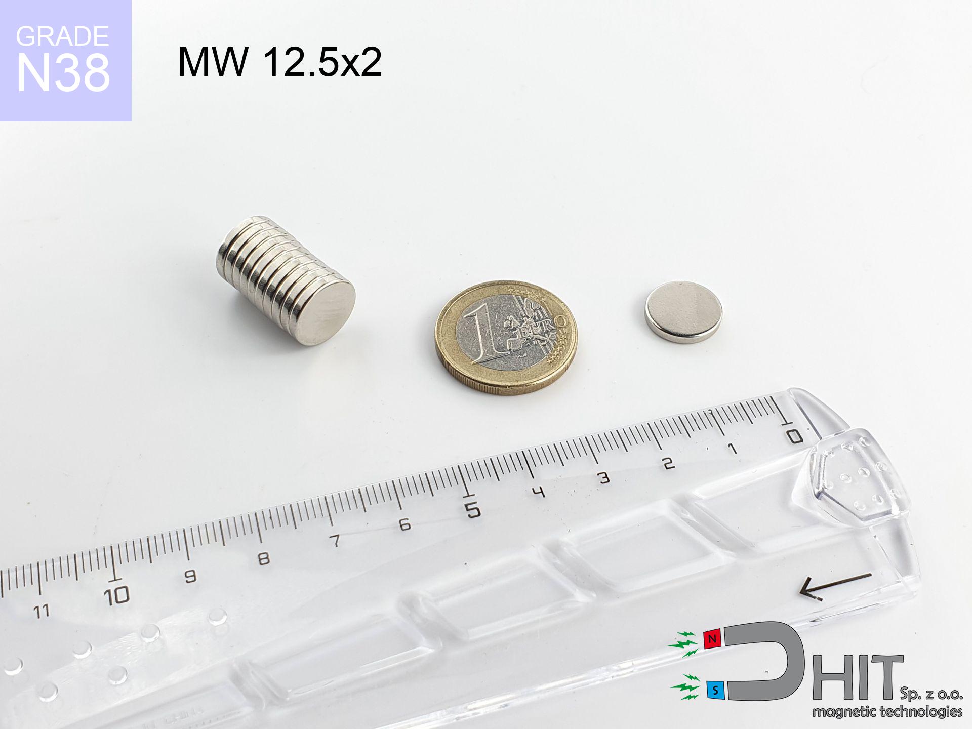
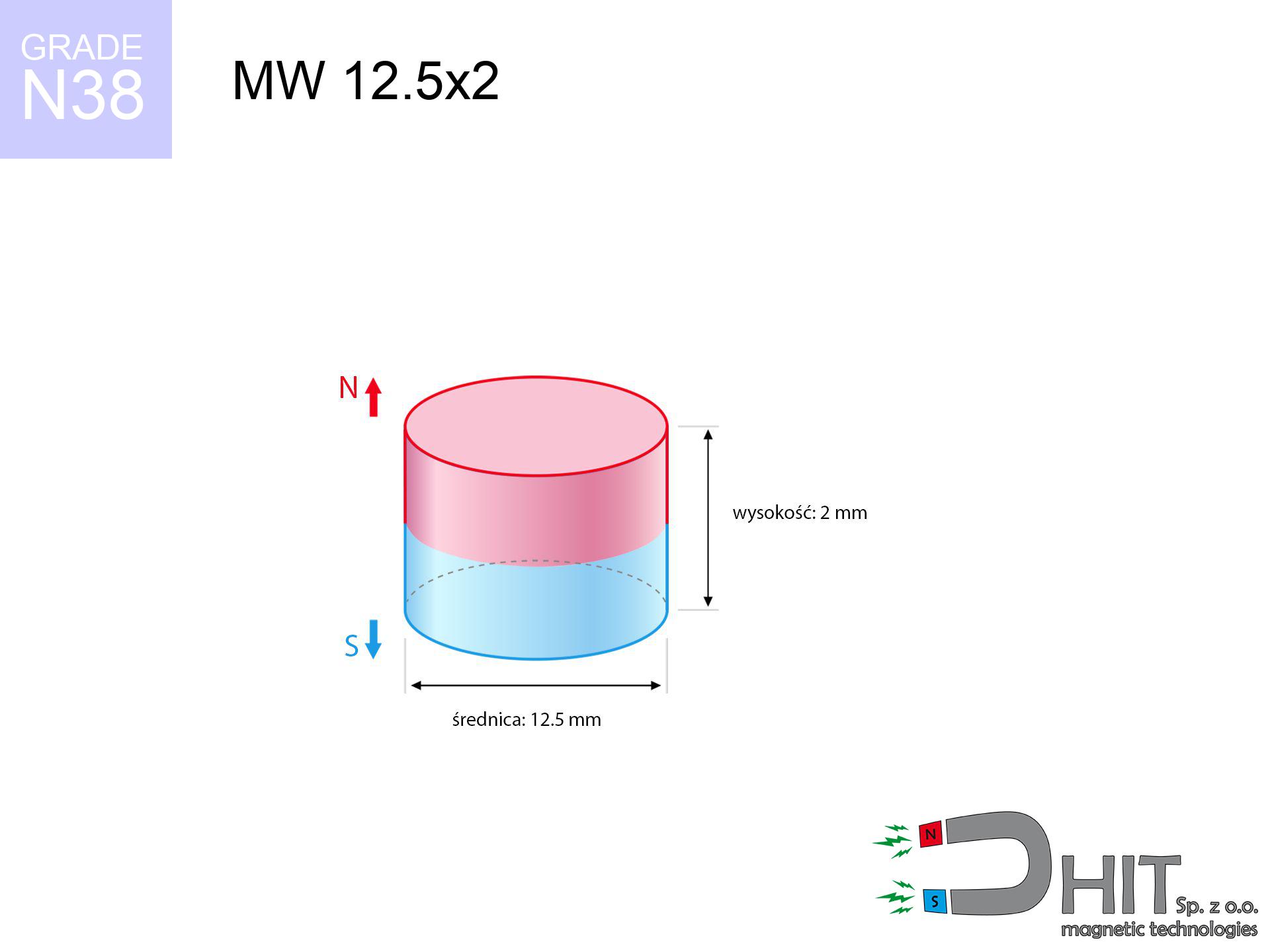
MW 12.5x2 / N38 - cylindrical magnet
cylindrical magnet
Catalog no 010014
GTIN/EAN: 5906301810131
Diameter Ø
12.5 mm [±0,1 mm]
Height
2 mm [±0,1 mm]
Weight
1.84 g
Magnetization Direction
↑ axial
Load capacity
1.42 kg / 13.89 N
Magnetic Induction
188.88 mT / 1889 Gs
Coating
[NiCuNi] Nickel
0.935 ZŁ with VAT / pcs + price for transport
0.760 ZŁ net + 23% VAT / pcs
bulk discounts:
Need more?Engineering report for this magnet
Full PDF analysis: pull and shear force, effect of distance, temperature and plate thickness, safety distances and the demagnetization curve.
Contact us by phone
+48 22 499 98 98
if you prefer send us a note by means of
request form
the contact page.
Weight along with form of magnetic components can be checked with our
online calculation tool.
Same-day processing for orders placed before 14:00.
Physical properties - MW 12.5x2 / N38 - cylindrical magnet
Specification / characteristics - MW 12.5x2 / N38 - cylindrical magnet
| properties | values |
|---|---|
| Cat. no. | 010014 |
| GTIN/EAN | 5906301810131 |
| Production/Distribution | Dhit sp. z o.o. |
| Country of origin | Poland / China / Germany |
| Customs code | 85059029 |
| Diameter Ø | 12.5 mm [±0,1 mm] |
| Height | 2 mm [±0,1 mm] |
| Weight | 1.84 g |
| Magnetization Direction | ↑ axial |
| Load capacity ~ ? | 1.42 kg / 13.89 N |
| Magnetic Induction ~ ? | 188.88 mT / 1889 Gs |
| Coating | [NiCuNi] Nickel |
| Manufacturing Tolerance | ±0.1 mm |
Magnetic properties of material N38
| properties | values | units |
|---|---|---|
| remenance Br [min. - max.] ? | 12.2-12.6 | kGs |
| remenance Br [min. - max.] ? | 1220-1260 | mT |
| coercivity bHc ? | 10.8-11.5 | kOe |
| coercivity bHc ? | 860-915 | kA/m |
| actual internal force iHc | ≥ 12 | kOe |
| actual internal force iHc | ≥ 955 | kA/m |
| energy density [min. - max.] ? | 36-38 | BH max MGOe |
| energy density [min. - max.] ? | 287-303 | BH max KJ/m |
| max. temperature ? | ≤ 80 | °C |
Physical properties of sintered neodymium magnets Nd2Fe14B at 20°C
| properties | values | units |
|---|---|---|
| Vickers hardness | ≥550 | Hv |
| Density | ≥7.4 | g/cm3 |
| Curie Temperature TC | 312 - 380 | °C |
| Curie Temperature TF | 593 - 716 | °F |
| Specific resistance | 150 | μΩ⋅cm |
| Bending strength | 250 | MPa |
| Compressive strength | 1000~1100 | MPa |
| Thermal expansion parallel (∥) to orientation (M) | (3-4) x 10-6 | °C-1 |
| Thermal expansion perpendicular (⊥) to orientation (M) | -(1-3) x 10-6 | °C-1 |
| Young's modulus | 1.7 x 10⁴ | kg/mm² |
Physical modeling of the magnet - report
Presented values constitute the direct effect of a mathematical calculation. Results rely on algorithms for the class Nd2Fe14B. Operational performance might slightly differ from theoretical values. Treat these calculations as a preliminary roadmap for designers.
Table 1: Static force (force vs distance) - interaction chart
MW 12.5x2 / N38
| Distance (mm) | Induction (Gauss) / mT | Pull Force (kg/lbs/g/N) | Risk Status |
|---|---|---|---|
| 0 mm |
1888 Gs
188.8 mT
|
1.42 kg / 3.13 LBS
1420.0 g / 13.9 N
|
low risk |
| 1 mm |
1703 Gs
170.3 mT
|
1.16 kg / 2.55 LBS
1155.6 g / 11.3 N
|
low risk |
| 2 mm |
1453 Gs
145.3 mT
|
0.84 kg / 1.85 LBS
840.3 g / 8.2 N
|
low risk |
| 3 mm |
1190 Gs
119.0 mT
|
0.56 kg / 1.24 LBS
564.1 g / 5.5 N
|
low risk |
| 5 mm |
752 Gs
75.2 mT
|
0.23 kg / 0.50 LBS
225.0 g / 2.2 N
|
low risk |
| 10 mm |
241 Gs
24.1 mT
|
0.02 kg / 0.05 LBS
23.2 g / 0.2 N
|
low risk |
| 15 mm |
96 Gs
9.6 mT
|
0.00 kg / 0.01 LBS
3.7 g / 0.0 N
|
low risk |
| 20 mm |
46 Gs
4.6 mT
|
0.00 kg / 0.00 LBS
0.9 g / 0.0 N
|
low risk |
| 30 mm |
15 Gs
1.5 mT
|
0.00 kg / 0.00 LBS
0.1 g / 0.0 N
|
low risk |
| 50 mm |
4 Gs
0.4 mT
|
0.00 kg / 0.00 LBS
0.0 g / 0.0 N
|
low risk |
Table 2: Slippage force (vertical surface)
MW 12.5x2 / N38
| Distance (mm) | Friction coefficient | Pull Force (kg/lbs/g/N) |
|---|---|---|
| 0 mm | Stal (~0.2) |
0.28 kg / 0.63 LBS
284.0 g / 2.8 N
|
| 1 mm | Stal (~0.2) |
0.23 kg / 0.51 LBS
232.0 g / 2.3 N
|
| 2 mm | Stal (~0.2) |
0.17 kg / 0.37 LBS
168.0 g / 1.6 N
|
| 3 mm | Stal (~0.2) |
0.11 kg / 0.25 LBS
112.0 g / 1.1 N
|
| 5 mm | Stal (~0.2) |
0.05 kg / 0.10 LBS
46.0 g / 0.5 N
|
| 10 mm | Stal (~0.2) |
0.00 kg / 0.01 LBS
4.0 g / 0.0 N
|
| 15 mm | Stal (~0.2) |
0.00 kg / 0.00 LBS
0.0 g / 0.0 N
|
| 20 mm | Stal (~0.2) |
0.00 kg / 0.00 LBS
0.0 g / 0.0 N
|
| 30 mm | Stal (~0.2) |
0.00 kg / 0.00 LBS
0.0 g / 0.0 N
|
| 50 mm | Stal (~0.2) |
0.00 kg / 0.00 LBS
0.0 g / 0.0 N
|
Table 3: Vertical assembly (sliding) - vertical pull
MW 12.5x2 / N38
| Surface type | Friction coefficient / % Mocy | Max load (kg/lbs/g/N) |
|---|---|---|
| Raw steel |
µ = 0.3
30% Nominalnej Siły
|
0.43 kg / 0.94 LBS
426.0 g / 4.2 N
|
| Painted steel (standard) |
µ = 0.2
20% Nominalnej Siły
|
0.28 kg / 0.63 LBS
284.0 g / 2.8 N
|
| Oily/slippery steel |
µ = 0.1
10% Nominalnej Siły
|
0.14 kg / 0.31 LBS
142.0 g / 1.4 N
|
| Magnet with anti-slip rubber |
µ = 0.5
50% Nominalnej Siły
|
0.71 kg / 1.57 LBS
710.0 g / 7.0 N
|
Table 4: Steel thickness (substrate influence) - sheet metal selection
MW 12.5x2 / N38
| Steel thickness (mm) | % power | Real pull force (kg/lbs/g/N) |
|---|---|---|
| 0.5 mm |
|
0.14 kg / 0.31 LBS
142.0 g / 1.4 N
|
| 1 mm |
|
0.36 kg / 0.78 LBS
355.0 g / 3.5 N
|
| 2 mm |
|
0.71 kg / 1.57 LBS
710.0 g / 7.0 N
|
| 3 mm |
|
1.07 kg / 2.35 LBS
1065.0 g / 10.4 N
|
| 5 mm |
|
1.42 kg / 3.13 LBS
1420.0 g / 13.9 N
|
| 10 mm |
|
1.42 kg / 3.13 LBS
1420.0 g / 13.9 N
|
| 11 mm |
|
1.42 kg / 3.13 LBS
1420.0 g / 13.9 N
|
| 12 mm |
|
1.42 kg / 3.13 LBS
1420.0 g / 13.9 N
|
Table 5: Working in heat (stability) - resistance threshold
MW 12.5x2 / N38
| Ambient temp. (°C) | Power loss | Remaining pull (kg/lbs/g/N) | Status |
|---|---|---|---|
| 20 °C | 0.0% |
1.42 kg / 3.13 LBS
1420.0 g / 13.9 N
|
OK |
| 40 °C | -2.2% |
1.39 kg / 3.06 LBS
1388.8 g / 13.6 N
|
OK |
| 60 °C | -4.4% |
1.36 kg / 2.99 LBS
1357.5 g / 13.3 N
|
|
| 80 °C | -6.6% |
1.33 kg / 2.92 LBS
1326.3 g / 13.0 N
|
|
| 100 °C | -28.8% |
1.01 kg / 2.23 LBS
1011.0 g / 9.9 N
|
Table 6: Two magnets (attraction) - field range
MW 12.5x2 / N38
| Gap (mm) | Attraction (kg/lbs) (N-S) | Shear Force (kg/lbs/g/N) | Repulsion (kg/lbs) (N-N) |
|---|---|---|---|
| 0 mm |
2.70 kg / 5.95 LBS
3 338 Gs
|
0.40 kg / 0.89 LBS
405 g / 4.0 N
|
N/A |
| 1 mm |
2.47 kg / 5.45 LBS
3 616 Gs
|
0.37 kg / 0.82 LBS
371 g / 3.6 N
|
2.23 kg / 4.91 LBS
~0 Gs
|
| 2 mm |
2.20 kg / 4.84 LBS
3 407 Gs
|
0.33 kg / 0.73 LBS
329 g / 3.2 N
|
1.98 kg / 4.36 LBS
~0 Gs
|
| 3 mm |
1.89 kg / 4.18 LBS
3 165 Gs
|
0.28 kg / 0.63 LBS
284 g / 2.8 N
|
1.71 kg / 3.76 LBS
~0 Gs
|
| 5 mm |
1.32 kg / 2.91 LBS
2 640 Gs
|
0.20 kg / 0.44 LBS
198 g / 1.9 N
|
1.19 kg / 2.62 LBS
~0 Gs
|
| 10 mm |
0.43 kg / 0.94 LBS
1 503 Gs
|
0.06 kg / 0.14 LBS
64 g / 0.6 N
|
0.38 kg / 0.85 LBS
~0 Gs
|
| 20 mm |
0.04 kg / 0.10 LBS
483 Gs
|
0.01 kg / 0.01 LBS
7 g / 0.1 N
|
0.04 kg / 0.09 LBS
~0 Gs
|
| 50 mm |
0.00 kg / 0.00 LBS
51 Gs
|
0.00 kg / 0.00 LBS
0 g / 0.0 N
|
0.00 kg / 0.00 LBS
~0 Gs
|
| 60 mm |
0.00 kg / 0.00 LBS
31 Gs
|
0.00 kg / 0.00 LBS
0 g / 0.0 N
|
0.00 kg / 0.00 LBS
~0 Gs
|
| 70 mm |
0.00 kg / 0.00 LBS
20 Gs
|
0.00 kg / 0.00 LBS
0 g / 0.0 N
|
0.00 kg / 0.00 LBS
~0 Gs
|
| 80 mm |
0.00 kg / 0.00 LBS
14 Gs
|
0.00 kg / 0.00 LBS
0 g / 0.0 N
|
0.00 kg / 0.00 LBS
~0 Gs
|
| 90 mm |
0.00 kg / 0.00 LBS
10 Gs
|
0.00 kg / 0.00 LBS
0 g / 0.0 N
|
0.00 kg / 0.00 LBS
~0 Gs
|
| 100 mm |
0.00 kg / 0.00 LBS
7 Gs
|
0.00 kg / 0.00 LBS
0 g / 0.0 N
|
0.00 kg / 0.00 LBS
~0 Gs
|
Table 7: Protective zones (implants) - warnings
MW 12.5x2 / N38
| Object / Device | Limit (Gauss) / mT | Safe distance |
|---|---|---|
| Pacemaker | 5 Gs (0.5 mT) | 4.5 cm |
| Hearing aid | 10 Gs (1.0 mT) | 3.5 cm |
| Mechanical watch | 20 Gs (2.0 mT) | 3.0 cm |
| Mobile device | 40 Gs (4.0 mT) | 2.5 cm |
| Car key | 50 Gs (5.0 mT) | 2.0 cm |
| Payment card | 400 Gs (40.0 mT) | 1.0 cm |
| HDD hard drive | 600 Gs (60.0 mT) | 1.0 cm |
Table 8: Impact energy (kinetic energy) - warning
MW 12.5x2 / N38
| Start from (mm) | Speed (km/h) | Energy (J) | Predicted outcome |
|---|---|---|---|
| 10 mm |
28.30 km/h
(7.86 m/s)
|
0.06 J | |
| 30 mm |
48.53 km/h
(13.48 m/s)
|
0.17 J | |
| 50 mm |
62.65 km/h
(17.40 m/s)
|
0.28 J | |
| 100 mm |
88.60 km/h
(24.61 m/s)
|
0.56 J |
Table 9: Surface protection spec
MW 12.5x2 / N38
| Technical parameter | Value / Description |
|---|---|
| Coating type | [NiCuNi] Nickel |
| Layer structure | Nickel - Copper - Nickel |
| Layer thickness | 10-20 µm |
| Salt spray test (SST) ? | 24 h |
| Recommended environment | Indoors only (dry) |
Table 10: Electrical data (Flux)
MW 12.5x2 / N38
| Parameter | Value | SI Unit / Description |
|---|---|---|
| Magnetic Flux | 2 810 Mx | 28.1 µWb |
| Pc Coefficient | 0.24 | Low (Flat) |
Table 11: Physics of underwater searching
MW 12.5x2 / N38
| Environment | Effective steel pull | Effect |
|---|---|---|
| Air (land) | 1.42 kg | Standard |
| Water (riverbed) |
1.63 kg
(+0.21 kg buoyancy gain)
|
+14.5% |
1. Shear force
*Note: On a vertical wall, the magnet holds merely approx. 20-30% of its nominal pull.
2. Steel thickness impact
*Thin steel (e.g. computer case) significantly reduces the holding force.
3. Temperature resistance
*For standard magnets, the critical limit is 80°C.
4. Demagnetization curve and operating point (B-H)
chart generated for the permeance coefficient Pc (Permeance Coefficient) = 0.24
This simulation demonstrates the magnetic stability of the selected magnet under specific geometric conditions. The solid red line represents the demagnetization curve (material potential), while the dashed blue line is the load line based on the magnet's geometry. The Pc (Permeance Coefficient), also known as the load line slope, is a dimensionless value that describes the relationship between the magnet's shape and its magnetic stability. The intersection of these two lines (the black dot) is the operating point — it determines the actual magnetic flux density generated by the magnet in this specific configuration. A higher Pc value means the magnet is more 'slender' (tall relative to its area), resulting in a higher operating point and better resistance to irreversible demagnetization caused by external fields or temperature. A value of 0.42 is relatively low (typical for flat magnets), meaning the operating point is closer to the 'knee' of the curve — caution is advised when operating at temperatures near the maximum limit to avoid strength loss.
Elemental analysis
| iron (Fe) | 64% – 68% |
| neodymium (Nd) | 29% – 32% |
| boron (B) | 1.1% – 1.2% |
| dysprosium (Dy) | 0.5% – 2.0% |
| coating (Ni-Cu-Ni) | < 0.05% |
Sustainability
| recyclability (EoL) | 100% |
| recycled raw materials | ~10% (pre-cons) |
| carbon footprint | low / zredukowany |
| waste code (EWC) | 16 02 16 |
Other proposals


![SM 32x500 [2xM8] / N52 - magnetic separator](https://cdn3.dhit.pl/graphics/products/sm-32x500-2xm8-rub.jpg "SM 32x500 [2xM8] / N52 - magnetic separator")

Advantages and disadvantages of neodymium magnets.
Advantages
- Their magnetic field is maintained, and after around 10 years it drops only by ~1% (theoretically),
- Neodymium magnets are highly resistant to demagnetization caused by external magnetic fields,
- The use of an elegant finish of noble metals (nickel, gold, silver) causes the element to look better,
- Magnetic induction on the working part of the magnet remains very high,
- Through (appropriate) combination of ingredients, they can achieve high thermal strength, allowing for functioning at temperatures reaching 230°C and above...
- Possibility of individual machining as well as optimizing to specific applications,
- Fundamental importance in advanced technology sectors – they serve a role in mass storage devices, brushless drives, medical equipment, as well as industrial machines.
- Compactness – despite small sizes they generate large force, making them ideal for precision applications
Limitations
- At strong impacts they can crack, therefore we advise placing them in strong housings. A metal housing provides additional protection against damage and increases the magnet's durability.
- Neodymium magnets lose their power under the influence of heating. As soon as 80°C is exceeded, many of them start losing their power. Therefore, we recommend our special magnets marked [AH], which maintain durability even at temperatures up to 230°C
- When exposed to humidity, magnets start to rust. For applications outside, it is recommended to use protective magnets, such as those in rubber or plastics, which secure oxidation and corrosion.
- Limited ability of producing nuts in the magnet and complicated shapes - recommended is a housing - magnet mounting.
- Health risk resulting from small fragments of magnets pose a threat, if swallowed, which is particularly important in the context of child health protection. It is also worth noting that small components of these magnets are able to disrupt the diagnostic process medical after entering the body.
- High unit price – neodymium magnets are more expensive than other types of magnets (e.g. ferrite), which can limit application in large quantities
Pull force analysis
Breakaway strength of the magnet in ideal conditions – what contributes to it?
- with the use of a yoke made of special test steel, ensuring maximum field concentration
- possessing a thickness of at least 10 mm to ensure full flux closure
- with an ground touching surface
- under conditions of no distance (surface-to-surface)
- during detachment in a direction perpendicular to the plane
- at standard ambient temperature
Impact of factors on magnetic holding capacity in practice
- Distance – the presence of foreign body (rust, tape, gap) interrupts the magnetic circuit, which reduces power steeply (even by 50% at 0.5 mm).
- Force direction – remember that the magnet has greatest strength perpendicularly. Under sliding down, the capacity drops significantly, often to levels of 20-30% of the maximum value.
- Steel thickness – too thin plate does not accept the full field, causing part of the flux to be escaped to the other side.
- Metal type – different alloys reacts the same. High carbon content worsen the interaction with the magnet.
- Smoothness – ideal contact is possible only on smooth steel. Rough texture create air cushions, weakening the magnet.
- Thermal environment – temperature increase results in weakening of force. Check the thermal limit for a given model.
Lifting capacity was determined using a polished steel plate of suitable thickness (min. 20 mm), under perpendicular pulling force, in contrast under attempts to slide the magnet the lifting capacity is smaller. Additionally, even a minimal clearance between the magnet’s surface and the plate decreases the lifting capacity.
Warnings
Power loss in heat
Standard neodymium magnets (N-type) lose power when the temperature goes above 80°C. This process is irreversible.
Mechanical processing
Fire warning: Neodymium dust is highly flammable. Do not process magnets without safety gear as this may cause fire.
Pinching danger
Danger of trauma: The attraction force is so great that it can cause blood blisters, pinching, and broken bones. Protective gloves are recommended.
No play value
NdFeB magnets are not suitable for play. Eating several magnets can lead to them pinching intestinal walls, which constitutes a direct threat to life and requires immediate surgery.
Health Danger
Life threat: Strong magnets can turn off heart devices and defibrillators. Stay away if you have medical devices.
Powerful field
Before use, check safety instructions. Uncontrolled attraction can destroy the magnet or hurt your hand. Be predictive.
Eye protection
Beware of splinters. Magnets can explode upon violent connection, launching shards into the air. We recommend safety glasses.
Sensitization to coating
Nickel alert: The Ni-Cu-Ni coating contains nickel. If redness occurs, immediately stop handling magnets and wear gloves.
Keep away from electronics
A powerful magnetic field interferes with the operation of magnetometers in smartphones and GPS navigation. Do not bring magnets near a smartphone to avoid breaking the sensors.
Threat to electronics
Avoid bringing magnets near a wallet, laptop, or screen. The magnetism can irreversibly ruin these devices and wipe information from cards.
Tabela kosztu i czasu dostawy
Płatność przed wysyłką:

GLS kurier
Przesyłka będzie u Ciebie za 2-3 dni
14.99 ZŁ

InPost Paczkomaty 24/7
Przesyłka będzie u Ciebie za 1-2 dni
12.30 ZŁ
Płatność przy odbiorze (pobranie):
GLS kurier
Przesyłka będzie u Ciebie za 1-2 dni
23.00 ZŁ
Rate the product
Your rating