
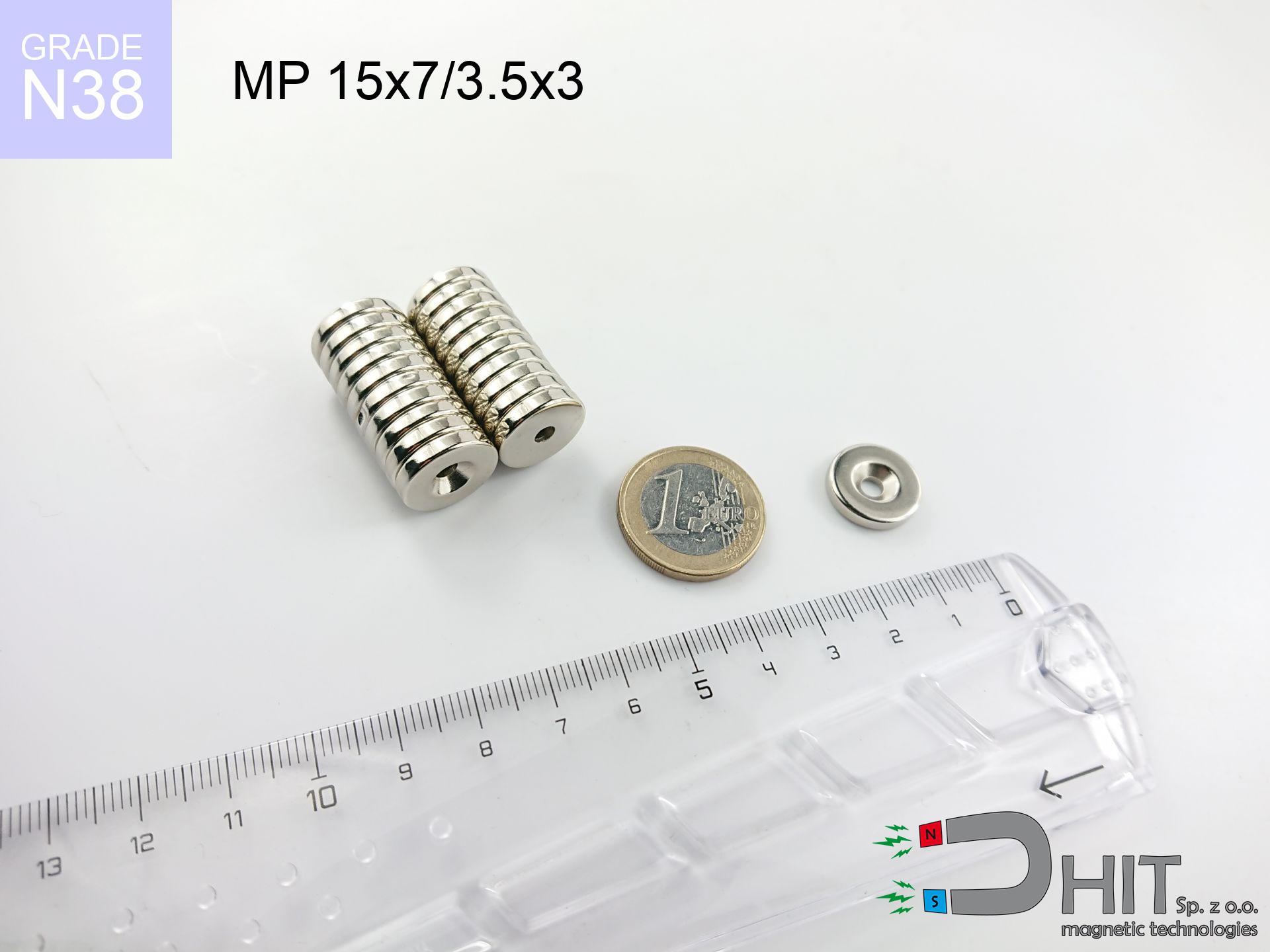
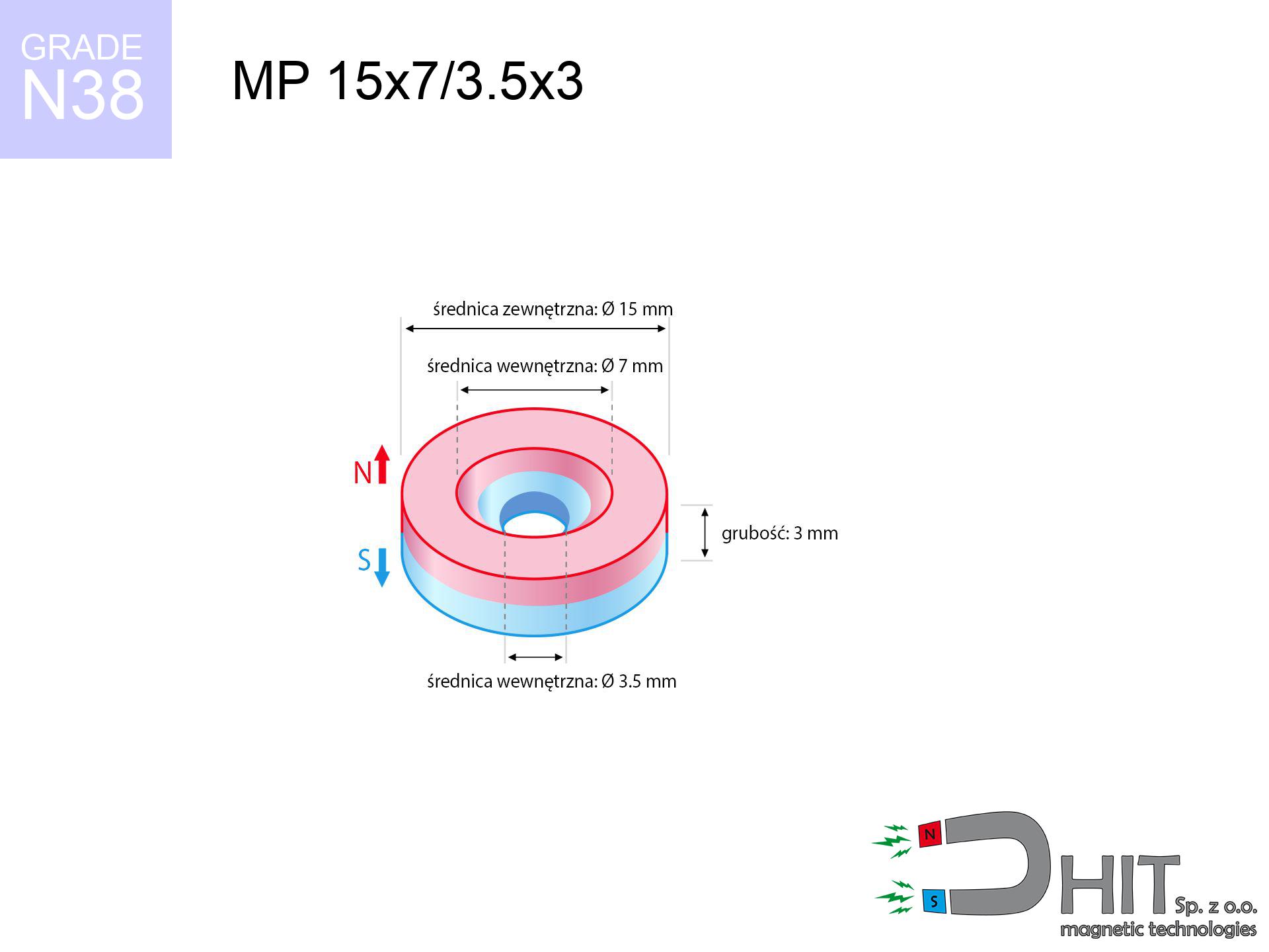
MP 15x7/3.5x3 / N38 - ring magnet
ring magnet
Catalog no 030182
GTIN/EAN: 5906301811992
- Diameter
- 15 mm [±0,1 mm]
- internal diameter Ø
- 7/3.5 mm [±0,1 mm]
- Height
- 3 mm [±0,1 mm]
- Weight
- 3.76 g
- Magnetization Direction
- ↑ axial
- Coating
- [NiCuNi] Nickel
1.747 zł with VAT / pcs + price for transport
1.420 zł net + 23% VAT / pcs
bulk discounts:
Need more?Engineering report for this magnet
Full PDF analysis: pull and shear force, effect of distance, temperature and plate thickness, safety distances and the demagnetization curve.
Give us a call
+48 888 99 98 98
if you prefer send us a note by means of
request form
the contact page.
Weight and shape of a neodymium magnet can be calculated using our
online calculation tool.
Same-day shipping for orders placed before 14:00.
Technical parameters of the product - MP 15x7/3.5x3 / N38 - ring magnet
Specification / characteristics - MP 15x7/3.5x3 / N38 - ring magnet
| properties | values |
|---|---|
| Cat. no. | 030182 |
| GTIN/EAN | 5906301811992 |
| Production/Distribution | Dhit sp. z o.o. |
| Country of origin | Poland / China / Germany |
| Customs code | 85059029 |
| Diameter | 15 mm [±0,1 mm] |
| internal diameter Ø | 7/3.5 mm [±0,1 mm] |
| Height | 3 mm [±0,1 mm] |
| Weight | 3.76 g |
| Magnetization Direction | ↑ axial |
| Load capacity ~ ? | 2.71 kg / 26.61 N |
| Magnetic Induction ~ ? | 230.16 mT / 2302 Gs |
| Coating | [NiCuNi] Nickel |
| Manufacturing Tolerance | ±0.1 mm |
Magnetic properties of material N38
| properties | values | units |
|---|---|---|
| remenance Br [min. - max.] ? | 12.2-12.6 | kGs |
| remenance Br [min. - max.] ? | 1220-1260 | mT |
| coercivity bHc ? | 10.8-11.5 | kOe |
| coercivity bHc ? | 860-915 | kA/m |
| actual internal force iHc | ≥ 12 | kOe |
| actual internal force iHc | ≥ 955 | kA/m |
| energy density [min. - max.] ? | 36-38 | BH max MGOe |
| energy density [min. - max.] ? | 287-303 | BH max KJ/m |
| max. temperature ? | ≤ 80 | °C |
Physical properties of sintered neodymium magnets Nd2Fe14B at 20°C
| properties | values | units |
|---|---|---|
| Vickers hardness | ≥550 | Hv |
| Density | ≥7.4 | g/cm3 |
| Curie Temperature TC | 312 - 380 | °C |
| Curie Temperature TF | 593 - 716 | °F |
| Specific resistance | 150 | μΩ⋅cm |
| Bending strength | 250 | MPa |
| Compressive strength | 1000~1100 | MPa |
| Thermal expansion parallel (∥) to orientation (M) | (3-4) x 10-6 | °C-1 |
| Thermal expansion perpendicular (⊥) to orientation (M) | -(1-3) x 10-6 | °C-1 |
| Young's modulus | 1.7 x 10⁴ | kg/mm² |
Technical modeling of the assembly - report
The following information are the result of a engineering calculation. Results are based on algorithms for the class Nd2Fe14B. Real-world performance might slightly deviate from the simulation results. Use these data as a supplementary guide during assembly planning.
Table 1: Static pull force (force vs gap) - power drop
MP 15x7/3.5x3 / N38
| Distance (mm) | Induction (Gauss) / mT | Pull Force (kg/lbs/g/N) | Risk Status |
|---|---|---|---|
| 0 mm |
1995 Gs
199.5 mT
|
2.71 kg / 5.97 pounds
2710.0 g / 26.6 N
|
strong |
| 1 mm |
1833 Gs
183.3 mT
|
2.29 kg / 5.05 pounds
2289.1 g / 22.5 N
|
strong |
| 2 mm |
1618 Gs
161.8 mT
|
1.78 kg / 3.93 pounds
1784.1 g / 17.5 N
|
weak grip |
| 3 mm |
1385 Gs
138.5 mT
|
1.31 kg / 2.88 pounds
1307.5 g / 12.8 N
|
weak grip |
| 5 mm |
959 Gs
95.9 mT
|
0.63 kg / 1.38 pounds
627.1 g / 6.2 N
|
weak grip |
| 10 mm |
362 Gs
36.2 mT
|
0.09 kg / 0.20 pounds
89.3 g / 0.9 N
|
weak grip |
| 15 mm |
156 Gs
15.6 mT
|
0.02 kg / 0.04 pounds
16.5 g / 0.2 N
|
weak grip |
| 20 mm |
78 Gs
7.8 mT
|
0.00 kg / 0.01 pounds
4.1 g / 0.0 N
|
weak grip |
| 30 mm |
27 Gs
2.7 mT
|
0.00 kg / 0.00 pounds
0.5 g / 0.0 N
|
weak grip |
| 50 mm |
6 Gs
0.6 mT
|
0.00 kg / 0.00 pounds
0.0 g / 0.0 N
|
weak grip |
Table 2: Vertical load (vertical surface)
MP 15x7/3.5x3 / N38
| Distance (mm) | Friction coefficient | Pull Force (kg/lbs/g/N) |
|---|---|---|
| 0 mm | Stal (~0.2) |
0.54 kg / 1.19 pounds
542.0 g / 5.3 N
|
| 1 mm | Stal (~0.2) |
0.46 kg / 1.01 pounds
458.0 g / 4.5 N
|
| 2 mm | Stal (~0.2) |
0.36 kg / 0.78 pounds
356.0 g / 3.5 N
|
| 3 mm | Stal (~0.2) |
0.26 kg / 0.58 pounds
262.0 g / 2.6 N
|
| 5 mm | Stal (~0.2) |
0.13 kg / 0.28 pounds
126.0 g / 1.2 N
|
| 10 mm | Stal (~0.2) |
0.02 kg / 0.04 pounds
18.0 g / 0.2 N
|
| 15 mm | Stal (~0.2) |
0.00 kg / 0.01 pounds
4.0 g / 0.0 N
|
| 20 mm | Stal (~0.2) |
0.00 kg / 0.00 pounds
0.0 g / 0.0 N
|
| 30 mm | Stal (~0.2) |
0.00 kg / 0.00 pounds
0.0 g / 0.0 N
|
| 50 mm | Stal (~0.2) |
0.00 kg / 0.00 pounds
0.0 g / 0.0 N
|
Table 3: Wall mounting (sliding) - behavior on slippery surfaces
MP 15x7/3.5x3 / N38
| Surface type | Friction coefficient / % Mocy | Max load (kg/lbs/g/N) |
|---|---|---|
| Raw steel |
µ = 0.3
30% Nominalnej Siły
|
0.81 kg / 1.79 pounds
813.0 g / 8.0 N
|
| Painted steel (standard) |
µ = 0.2
20% Nominalnej Siły
|
0.54 kg / 1.19 pounds
542.0 g / 5.3 N
|
| Oily/slippery steel |
µ = 0.1
10% Nominalnej Siły
|
0.27 kg / 0.60 pounds
271.0 g / 2.7 N
|
| Magnet with anti-slip rubber |
µ = 0.5
50% Nominalnej Siły
|
1.36 kg / 2.99 pounds
1355.0 g / 13.3 N
|
Table 4: Material efficiency (saturation) - sheet metal selection
MP 15x7/3.5x3 / N38
| Steel thickness (mm) | % power | Real pull force (kg/lbs/g/N) |
|---|---|---|
| 0.5 mm |
|
0.27 kg / 0.60 pounds
271.0 g / 2.7 N
|
| 1 mm |
|
0.68 kg / 1.49 pounds
677.5 g / 6.6 N
|
| 2 mm |
|
1.36 kg / 2.99 pounds
1355.0 g / 13.3 N
|
| 3 mm |
|
2.03 kg / 4.48 pounds
2032.5 g / 19.9 N
|
| 5 mm |
|
2.71 kg / 5.97 pounds
2710.0 g / 26.6 N
|
| 10 mm |
|
2.71 kg / 5.97 pounds
2710.0 g / 26.6 N
|
| 11 mm |
|
2.71 kg / 5.97 pounds
2710.0 g / 26.6 N
|
| 12 mm |
|
2.71 kg / 5.97 pounds
2710.0 g / 26.6 N
|
Table 5: Thermal stability (material behavior) - resistance threshold
MP 15x7/3.5x3 / N38
| Ambient temp. (°C) | Power loss | Remaining pull (kg/lbs/g/N) | Status |
|---|---|---|---|
| 20 °C | 0.0% |
2.71 kg / 5.97 pounds
2710.0 g / 26.6 N
|
OK |
| 40 °C | -2.2% |
2.65 kg / 5.84 pounds
2650.4 g / 26.0 N
|
OK |
| 60 °C | -4.4% |
2.59 kg / 5.71 pounds
2590.8 g / 25.4 N
|
|
| 80 °C | -6.6% |
2.53 kg / 5.58 pounds
2531.1 g / 24.8 N
|
|
| 100 °C | -28.8% |
1.93 kg / 4.25 pounds
1929.5 g / 18.9 N
|
Table 6: Two magnets (repulsion) - field range
MP 15x7/3.5x3 / N38
| Gap (mm) | Attraction (kg/lbs) (N-S) | Sliding Force (kg/lbs/g/N) | Repulsion (kg/lbs) (N-N) |
|---|---|---|---|
| 0 mm |
3.48 kg / 7.68 pounds
3 483 Gs
|
0.52 kg / 1.15 pounds
523 g / 5.1 N
|
N/A |
| 1 mm |
3.24 kg / 7.14 pounds
3 846 Gs
|
0.49 kg / 1.07 pounds
486 g / 4.8 N
|
2.91 kg / 6.43 pounds
~0 Gs
|
| 2 mm |
2.94 kg / 6.49 pounds
3 666 Gs
|
0.44 kg / 0.97 pounds
441 g / 4.3 N
|
2.65 kg / 5.84 pounds
~0 Gs
|
| 3 mm |
2.62 kg / 5.78 pounds
3 460 Gs
|
0.39 kg / 0.87 pounds
393 g / 3.9 N
|
2.36 kg / 5.20 pounds
~0 Gs
|
| 5 mm |
1.98 kg / 4.36 pounds
3 004 Gs
|
0.30 kg / 0.65 pounds
296 g / 2.9 N
|
1.78 kg / 3.92 pounds
~0 Gs
|
| 10 mm |
0.81 kg / 1.78 pounds
1 919 Gs
|
0.12 kg / 0.27 pounds
121 g / 1.2 N
|
0.73 kg / 1.60 pounds
~0 Gs
|
| 20 mm |
0.11 kg / 0.25 pounds
724 Gs
|
0.02 kg / 0.04 pounds
17 g / 0.2 N
|
0.10 kg / 0.23 pounds
~0 Gs
|
| 50 mm |
0.00 kg / 0.00 pounds
88 Gs
|
0.00 kg / 0.00 pounds
0 g / 0.0 N
|
0.00 kg / 0.00 pounds
~0 Gs
|
| 60 mm |
0.00 kg / 0.00 pounds
54 Gs
|
0.00 kg / 0.00 pounds
0 g / 0.0 N
|
0.00 kg / 0.00 pounds
~0 Gs
|
| 70 mm |
0.00 kg / 0.00 pounds
35 Gs
|
0.00 kg / 0.00 pounds
0 g / 0.0 N
|
0.00 kg / 0.00 pounds
~0 Gs
|
| 80 mm |
0.00 kg / 0.00 pounds
24 Gs
|
0.00 kg / 0.00 pounds
0 g / 0.0 N
|
0.00 kg / 0.00 pounds
~0 Gs
|
| 90 mm |
0.00 kg / 0.00 pounds
17 Gs
|
0.00 kg / 0.00 pounds
0 g / 0.0 N
|
0.00 kg / 0.00 pounds
~0 Gs
|
| 100 mm |
0.00 kg / 0.00 pounds
13 Gs
|
0.00 kg / 0.00 pounds
0 g / 0.0 N
|
0.00 kg / 0.00 pounds
~0 Gs
|
Table 7: Hazards (electronics) - warnings
MP 15x7/3.5x3 / N38
| Object / Device | Limit (Gauss) / mT | Safe distance |
|---|---|---|
| Pacemaker | 5 Gs (0.5 mT) | 5.5 cm |
| Hearing aid | 10 Gs (1.0 mT) | 4.5 cm |
| Timepiece | 20 Gs (2.0 mT) | 3.5 cm |
| Mobile device | 40 Gs (4.0 mT) | 3.0 cm |
| Remote | 50 Gs (5.0 mT) | 2.5 cm |
| Payment card | 400 Gs (40.0 mT) | 1.0 cm |
| HDD hard drive | 600 Gs (60.0 mT) | 1.0 cm |
Table 8: Collisions (cracking risk) - warning
MP 15x7/3.5x3 / N38
| Start from (mm) | Speed (km/h) | Energy (J) | Predicted outcome |
|---|---|---|---|
| 10 mm |
25.12 km/h
(6.98 m/s)
|
0.09 J | |
| 30 mm |
25.48 km/h
(7.08 m/s)
|
0.09 J | |
| 50 mm |
25.48 km/h
(7.08 m/s)
|
0.09 J | |
| 100 mm |
25.48 km/h
(7.08 m/s)
|
0.09 J |
Table 9: Anti-corrosion coating durability
MP 15x7/3.5x3 / N38
| Technical parameter | Value / Description |
|---|---|
| Coating type | [NiCuNi] Nickel |
| Layer structure | Nickel - Copper - Nickel |
| Layer thickness | 10-20 µm |
| Salt spray test (SST) ? | 24 h |
| Recommended environment | Indoors only (dry) |
Table 10: Electrical data (Flux)
MP 15x7/3.5x3 / N38
| Parameter | Value | SI Unit / Description |
|---|---|---|
| Magnetic Flux | 3 461 Mx | 34.6 µWb |
| Pc Coefficient | 0.26 | Low (Flat) |
Table 11: Physics of underwater searching
MP 15x7/3.5x3 / N38
| Environment | Effective steel pull | Effect |
|---|---|---|
| Air (land) | 2.71 kg | Standard |
| Water (riverbed) |
3.10 kg
(+0.39 kg buoyancy gain)
|
+14.5% |
1. Vertical hold
*Note: On a vertical surface, the magnet retains merely approx. 20-30% of its perpendicular strength.
2. Steel saturation
*Thin metal sheet (e.g. computer case) severely weakens the holding force.
3. Thermal stability
*For N38 material, the critical limit is 80°C.
4. Demagnetization curve and operating point (B-H)
chart generated for the permeance coefficient Pc (Permeance Coefficient) = 0.26
The chart above illustrates the magnetic characteristics of the material within the second quadrant of the hysteresis loop. The solid red line represents the demagnetization curve (material potential), while the dashed blue line is the load line based on the magnet's geometry. The Pc (Permeance Coefficient), also known as the load line slope, is a dimensionless value that describes the relationship between the magnet's shape and its magnetic stability. The intersection of these two lines (the black dot) is the operating point — it determines the actual magnetic flux density generated by the magnet in this specific configuration. A higher Pc value means the magnet is more 'slender' (tall relative to its area), resulting in a higher operating point and better resistance to irreversible demagnetization caused by external fields or temperature. A value of 0.42 is relatively low (typical for flat magnets), meaning the operating point is closer to the 'knee' of the curve — caution is advised when operating at temperatures near the maximum limit to avoid strength loss.
Chemical composition
| iron (Fe) | 64% – 68% |
| neodymium (Nd) | 29% – 32% |
| boron (B) | 1.1% – 1.2% |
| dysprosium (Dy) | 0.5% – 2.0% |
| coating (Ni-Cu-Ni) | < 0.05% |
Environmental data
| recyclability (EoL) | 100% |
| recycled raw materials | ~10% (pre-cons) |
| carbon footprint | low / zredukowany |
| waste code (EWC) | 16 02 16 |
View also offers


![UMP 75x25 [M10x3] GW F200 PLATINIUM Lina / N52 - search holder](https://cdn3.dhit.pl/graphics/products/ump-75x25-m10x3-gw-f200-platinium-lina-wiz.jpg "UMP 75x25 [M10x3] GW F200 PLATINIUM Lina / N52 - search holder")
![SM 32x250 [2xM8] / N42 - magnetic separator](https://cdn3.dhit.pl/graphics/products/sm-32x250-2xm8-kex.jpg "SM 32x250 [2xM8] / N42 - magnetic separator")
Advantages as well as disadvantages of rare earth magnets.
Strengths
- They virtually do not lose power, because even after ten years the performance loss is only ~1% (in laboratory conditions),
- They show high resistance to demagnetization induced by external field influence,
- By applying a shiny coating of silver, the element acquires an aesthetic look,
- They show high magnetic induction at the operating surface, which affects their effectiveness,
- Thanks to resistance to high temperature, they are capable of working (depending on the shape) even at temperatures up to 230°C and higher...
- Thanks to modularity in designing and the capacity to adapt to unusual requirements,
- Key role in future technologies – they are used in data components, brushless drives, advanced medical instruments, as well as industrial machines.
- Thanks to concentrated force, small magnets offer high operating force, with minimal size,
Disadvantages
- At very strong impacts they can break, therefore we advise placing them in special holders. A metal housing provides additional protection against damage and increases the magnet's durability.
- Neodymium magnets decrease their power under the influence of heating. As soon as 80°C is exceeded, many of them start losing their power. Therefore, we recommend our special magnets marked [AH], which maintain durability even at temperatures up to 230°C
- Due to the susceptibility of magnets to corrosion in a humid environment, we suggest using waterproof magnets made of rubber, plastic or other material immune to moisture, in case of application outdoors
- Limited possibility of producing nuts in the magnet and complex shapes - preferred is a housing - magnet mounting.
- Health risk to health – tiny shards of magnets are risky, when accidentally swallowed, which gains importance in the context of child safety. Additionally, tiny parts of these products are able to be problematic in diagnostics medical in case of swallowing.
- With mass production the cost of neodymium magnets is economically unviable,
Holding force characteristics
Magnetic strength at its maximum – what it depends on?
- on a plate made of structural steel, optimally conducting the magnetic flux
- possessing a massiveness of minimum 10 mm to avoid saturation
- characterized by lack of roughness
- under conditions of ideal adhesion (metal-to-metal)
- during detachment in a direction vertical to the plane
- in neutral thermal conditions
Determinants of practical lifting force of a magnet
- Gap between surfaces – even a fraction of a millimeter of separation (caused e.g. by varnish or dirt) drastically reduces the magnet efficiency, often by half at just 0.5 mm.
- Angle of force application – highest force is obtained only during pulling at a 90° angle. The force required to slide of the magnet along the surface is usually several times lower (approx. 1/5 of the lifting capacity).
- Substrate thickness – to utilize 100% power, the steel must be sufficiently thick. Thin sheet limits the attraction force (the magnet "punches through" it).
- Steel grade – the best choice is high-permeability steel. Cast iron may attract less.
- Plate texture – smooth surfaces ensure maximum contact, which increases force. Rough surfaces reduce efficiency.
- Operating temperature – NdFeB sinters have a sensitivity to temperature. At higher temperatures they are weaker, and at low temperatures they can be stronger (up to a certain limit).
Holding force was checked on a smooth steel plate of 20 mm thickness, when a perpendicular force was applied, however under parallel forces the lifting capacity is smaller. In addition, even a small distance between the magnet’s surface and the plate decreases the lifting capacity.
H&S for magnets
Nickel allergy
Warning for allergy sufferers: The nickel-copper-nickel coating consists of nickel. If an allergic reaction happens, immediately stop handling magnets and use protective gear.
Cards and drives
Very strong magnetic fields can corrupt files on credit cards, hard drives, and storage devices. Keep a distance of min. 10 cm.
Fragile material
Despite metallic appearance, neodymium is brittle and not impact-resistant. Do not hit, as the magnet may shatter into sharp, dangerous pieces.
Hand protection
Protect your hands. Two large magnets will join immediately with a force of several hundred kilograms, crushing everything in their path. Be careful!
Safe operation
Handle magnets with awareness. Their powerful strength can shock even professionals. Be vigilant and respect their power.
Heat sensitivity
Regular neodymium magnets (N-type) lose power when the temperature exceeds 80°C. This process is irreversible.
Danger to the youngest
Strictly keep magnets away from children. Risk of swallowing is high, and the effects of magnets clamping inside the body are tragic.
GPS and phone interference
A powerful magnetic field negatively affects the functioning of compasses in smartphones and GPS navigation. Do not bring magnets close to a device to prevent breaking the sensors.
Dust explosion hazard
Dust produced during machining of magnets is self-igniting. Avoid drilling into magnets unless you are an expert.
Medical implants
Life threat: Strong magnets can deactivate pacemakers and defibrillators. Stay away if you have medical devices.
Tabela kosztu i czasu dostawy
Płatność przed wysyłką:

GLS kurier
Przesyłka będzie u Ciebie za 2-3 dni
14.99 ZŁ

InPost Paczkomaty 24/7
Przesyłka będzie u Ciebie za 1-2 dni
12.30 ZŁ
Płatność przy odbiorze (pobranie):
GLS kurier
Przesyłka będzie u Ciebie za 1-2 dni
23.00 ZŁ
Rate the product
Your rating