

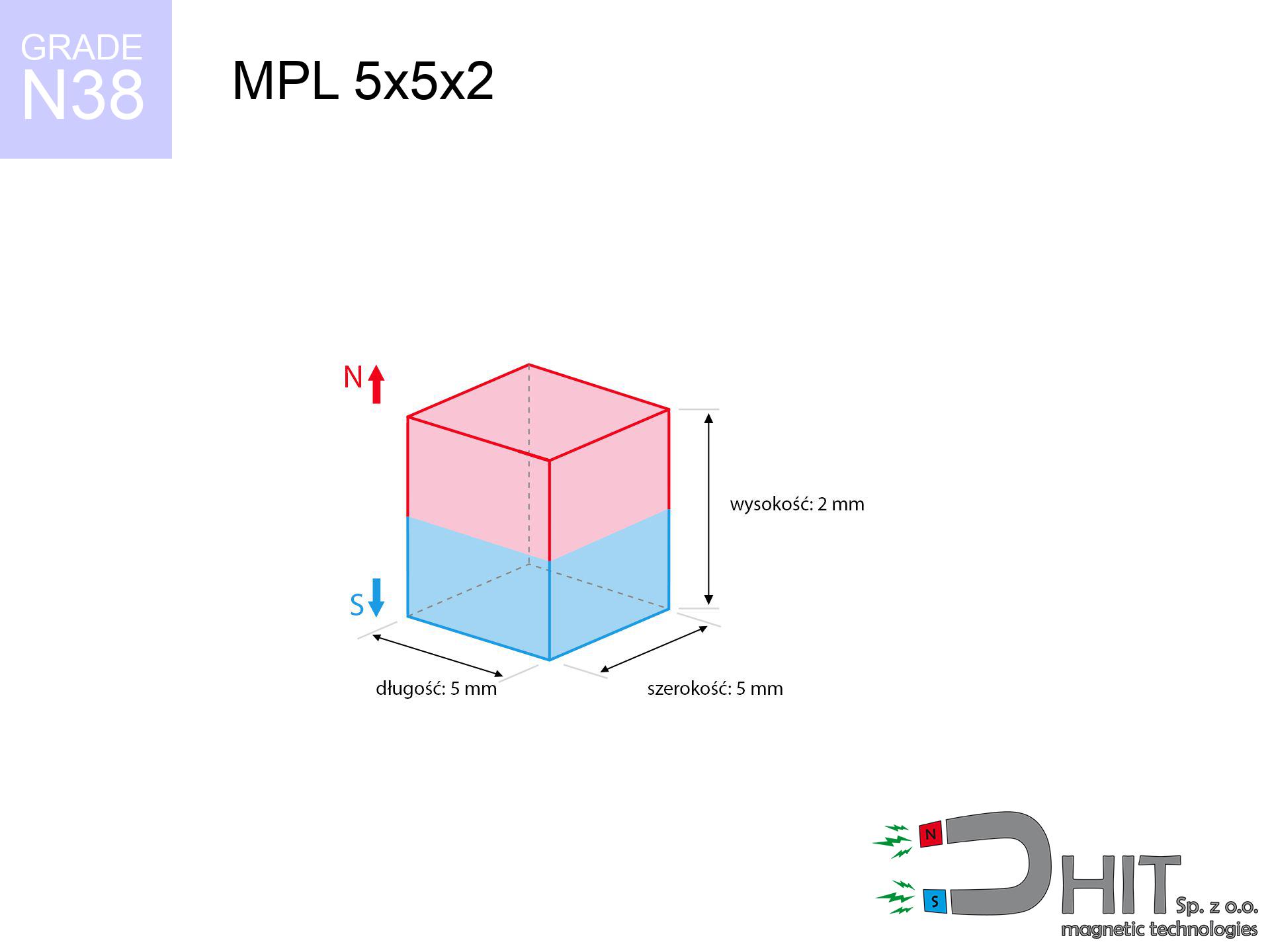
MPL 5x5x2 / N38 - lamellar magnet
lamellar magnet
Catalog no 020173
GTIN/EAN: 5906301811794
length
5 mm [±0,1 mm]
Width
5 mm [±0,1 mm]
Height
2 mm [±0,1 mm]
Weight
0.38 g
Magnetization Direction
↑ axial
Load capacity
0.77 kg / 7.57 N
Magnetic Induction
360.52 mT / 3605 Gs
Coating
[NiCuNi] Nickel
0.308 ZŁ with VAT / pcs + price for transport
0.250 ZŁ net + 23% VAT / pcs
bulk discounts:
Need more?Engineering report for this magnet
Full PDF analysis: pull and shear force, effect of distance, temperature and plate thickness, safety distances and the demagnetization curve.
Pick up the phone and ask
+48 888 99 98 98
otherwise let us know using
contact form
the contact form page.
Force and shape of a magnet can be reviewed using our
our magnetic calculator.
Same-day processing for orders placed before 14:00.
Product card - MPL 5x5x2 / N38 - lamellar magnet
Specification / characteristics - MPL 5x5x2 / N38 - lamellar magnet
| properties | values |
|---|---|
| Cat. no. | 020173 |
| GTIN/EAN | 5906301811794 |
| Production/Distribution | Dhit sp. z o.o. |
| Country of origin | Poland / China / Germany |
| Customs code | 85059029 |
| length | 5 mm [±0,1 mm] |
| Width | 5 mm [±0,1 mm] |
| Height | 2 mm [±0,1 mm] |
| Weight | 0.38 g |
| Magnetization Direction | ↑ axial |
| Load capacity ~ ? | 0.77 kg / 7.57 N |
| Magnetic Induction ~ ? | 360.52 mT / 3605 Gs |
| Coating | [NiCuNi] Nickel |
| Manufacturing Tolerance | ±0.1 mm |
Magnetic properties of material N38
| properties | values | units |
|---|---|---|
| remenance Br [min. - max.] ? | 12.2-12.6 | kGs |
| remenance Br [min. - max.] ? | 1220-1260 | mT |
| coercivity bHc ? | 10.8-11.5 | kOe |
| coercivity bHc ? | 860-915 | kA/m |
| actual internal force iHc | ≥ 12 | kOe |
| actual internal force iHc | ≥ 955 | kA/m |
| energy density [min. - max.] ? | 36-38 | BH max MGOe |
| energy density [min. - max.] ? | 287-303 | BH max KJ/m |
| max. temperature ? | ≤ 80 | °C |
Physical properties of sintered neodymium magnets Nd2Fe14B at 20°C
| properties | values | units |
|---|---|---|
| Vickers hardness | ≥550 | Hv |
| Density | ≥7.4 | g/cm3 |
| Curie Temperature TC | 312 - 380 | °C |
| Curie Temperature TF | 593 - 716 | °F |
| Specific resistance | 150 | μΩ⋅cm |
| Bending strength | 250 | MPa |
| Compressive strength | 1000~1100 | MPa |
| Thermal expansion parallel (∥) to orientation (M) | (3-4) x 10-6 | °C-1 |
| Thermal expansion perpendicular (⊥) to orientation (M) | -(1-3) x 10-6 | °C-1 |
| Young's modulus | 1.7 x 10⁴ | kg/mm² |
Engineering modeling of the product - data
The following data are the outcome of a mathematical calculation. Results rely on algorithms for the material Nd2Fe14B. Real-world parameters might slightly differ. Please consider these calculations as a supplementary guide when designing systems.
Table 1: Static pull force (pull vs gap) - characteristics
MPL 5x5x2 / N38
| Distance (mm) | Induction (Gauss) / mT | Pull Force (kg/lbs/g/N) | Risk Status |
|---|---|---|---|
| 0 mm |
3601 Gs
360.1 mT
|
0.77 kg / 1.70 LBS
770.0 g / 7.6 N
|
low risk |
| 1 mm |
2436 Gs
243.6 mT
|
0.35 kg / 0.78 LBS
352.2 g / 3.5 N
|
low risk |
| 2 mm |
1464 Gs
146.4 mT
|
0.13 kg / 0.28 LBS
127.3 g / 1.2 N
|
low risk |
| 3 mm |
872 Gs
87.2 mT
|
0.05 kg / 0.10 LBS
45.1 g / 0.4 N
|
low risk |
| 5 mm |
347 Gs
34.7 mT
|
0.01 kg / 0.02 LBS
7.2 g / 0.1 N
|
low risk |
| 10 mm |
68 Gs
6.8 mT
|
0.00 kg / 0.00 LBS
0.3 g / 0.0 N
|
low risk |
| 15 mm |
23 Gs
2.3 mT
|
0.00 kg / 0.00 LBS
0.0 g / 0.0 N
|
low risk |
| 20 mm |
10 Gs
1.0 mT
|
0.00 kg / 0.00 LBS
0.0 g / 0.0 N
|
low risk |
| 30 mm |
3 Gs
0.3 mT
|
0.00 kg / 0.00 LBS
0.0 g / 0.0 N
|
low risk |
| 50 mm |
1 Gs
0.1 mT
|
0.00 kg / 0.00 LBS
0.0 g / 0.0 N
|
low risk |
Table 2: Vertical load (wall)
MPL 5x5x2 / N38
| Distance (mm) | Friction coefficient | Pull Force (kg/lbs/g/N) |
|---|---|---|
| 0 mm | Stal (~0.2) |
0.15 kg / 0.34 LBS
154.0 g / 1.5 N
|
| 1 mm | Stal (~0.2) |
0.07 kg / 0.15 LBS
70.0 g / 0.7 N
|
| 2 mm | Stal (~0.2) |
0.03 kg / 0.06 LBS
26.0 g / 0.3 N
|
| 3 mm | Stal (~0.2) |
0.01 kg / 0.02 LBS
10.0 g / 0.1 N
|
| 5 mm | Stal (~0.2) |
0.00 kg / 0.00 LBS
2.0 g / 0.0 N
|
| 10 mm | Stal (~0.2) |
0.00 kg / 0.00 LBS
0.0 g / 0.0 N
|
| 15 mm | Stal (~0.2) |
0.00 kg / 0.00 LBS
0.0 g / 0.0 N
|
| 20 mm | Stal (~0.2) |
0.00 kg / 0.00 LBS
0.0 g / 0.0 N
|
| 30 mm | Stal (~0.2) |
0.00 kg / 0.00 LBS
0.0 g / 0.0 N
|
| 50 mm | Stal (~0.2) |
0.00 kg / 0.00 LBS
0.0 g / 0.0 N
|
Table 3: Wall mounting (sliding) - vertical pull
MPL 5x5x2 / N38
| Surface type | Friction coefficient / % Mocy | Max load (kg/lbs/g/N) |
|---|---|---|
| Raw steel |
µ = 0.3
30% Nominalnej Siły
|
0.23 kg / 0.51 LBS
231.0 g / 2.3 N
|
| Painted steel (standard) |
µ = 0.2
20% Nominalnej Siły
|
0.15 kg / 0.34 LBS
154.0 g / 1.5 N
|
| Oily/slippery steel |
µ = 0.1
10% Nominalnej Siły
|
0.08 kg / 0.17 LBS
77.0 g / 0.8 N
|
| Magnet with anti-slip rubber |
µ = 0.5
50% Nominalnej Siły
|
0.39 kg / 0.85 LBS
385.0 g / 3.8 N
|
Table 4: Steel thickness (saturation) - power losses
MPL 5x5x2 / N38
| Steel thickness (mm) | % power | Real pull force (kg/lbs/g/N) |
|---|---|---|
| 0.5 mm |
|
0.08 kg / 0.17 LBS
77.0 g / 0.8 N
|
| 1 mm |
|
0.19 kg / 0.42 LBS
192.5 g / 1.9 N
|
| 2 mm |
|
0.39 kg / 0.85 LBS
385.0 g / 3.8 N
|
| 3 mm |
|
0.58 kg / 1.27 LBS
577.5 g / 5.7 N
|
| 5 mm |
|
0.77 kg / 1.70 LBS
770.0 g / 7.6 N
|
| 10 mm |
|
0.77 kg / 1.70 LBS
770.0 g / 7.6 N
|
| 11 mm |
|
0.77 kg / 1.70 LBS
770.0 g / 7.6 N
|
| 12 mm |
|
0.77 kg / 1.70 LBS
770.0 g / 7.6 N
|
Table 5: Thermal stability (material behavior) - resistance threshold
MPL 5x5x2 / N38
| Ambient temp. (°C) | Power loss | Remaining pull (kg/lbs/g/N) | Status |
|---|---|---|---|
| 20 °C | 0.0% |
0.77 kg / 1.70 LBS
770.0 g / 7.6 N
|
OK |
| 40 °C | -2.2% |
0.75 kg / 1.66 LBS
753.1 g / 7.4 N
|
OK |
| 60 °C | -4.4% |
0.74 kg / 1.62 LBS
736.1 g / 7.2 N
|
|
| 80 °C | -6.6% |
0.72 kg / 1.59 LBS
719.2 g / 7.1 N
|
|
| 100 °C | -28.8% |
0.55 kg / 1.21 LBS
548.2 g / 5.4 N
|
Table 6: Magnet-Magnet interaction (repulsion) - field collision
MPL 5x5x2 / N38
| Gap (mm) | Attraction (kg/lbs) (N-S) | Shear Strength (kg/lbs/g/N) | Repulsion (kg/lbs) (N-N) |
|---|---|---|---|
| 0 mm |
2.00 kg / 4.41 LBS
5 058 Gs
|
0.30 kg / 0.66 LBS
300 g / 2.9 N
|
N/A |
| 1 mm |
1.42 kg / 3.13 LBS
6 070 Gs
|
0.21 kg / 0.47 LBS
213 g / 2.1 N
|
1.28 kg / 2.82 LBS
~0 Gs
|
| 2 mm |
0.91 kg / 2.02 LBS
4 871 Gs
|
0.14 kg / 0.30 LBS
137 g / 1.3 N
|
0.82 kg / 1.81 LBS
~0 Gs
|
| 3 mm |
0.56 kg / 1.23 LBS
3 801 Gs
|
0.08 kg / 0.18 LBS
83 g / 0.8 N
|
0.50 kg / 1.10 LBS
~0 Gs
|
| 5 mm |
0.20 kg / 0.43 LBS
2 254 Gs
|
0.03 kg / 0.06 LBS
29 g / 0.3 N
|
0.18 kg / 0.39 LBS
~0 Gs
|
| 10 mm |
0.02 kg / 0.04 LBS
695 Gs
|
0.00 kg / 0.01 LBS
3 g / 0.0 N
|
0.02 kg / 0.04 LBS
~0 Gs
|
| 20 mm |
0.00 kg / 0.00 LBS
136 Gs
|
0.00 kg / 0.00 LBS
0 g / 0.0 N
|
0.00 kg / 0.00 LBS
~0 Gs
|
| 50 mm |
0.00 kg / 0.00 LBS
11 Gs
|
0.00 kg / 0.00 LBS
0 g / 0.0 N
|
0.00 kg / 0.00 LBS
~0 Gs
|
| 60 mm |
0.00 kg / 0.00 LBS
7 Gs
|
0.00 kg / 0.00 LBS
0 g / 0.0 N
|
0.00 kg / 0.00 LBS
~0 Gs
|
| 70 mm |
0.00 kg / 0.00 LBS
4 Gs
|
0.00 kg / 0.00 LBS
0 g / 0.0 N
|
0.00 kg / 0.00 LBS
~0 Gs
|
| 80 mm |
0.00 kg / 0.00 LBS
3 Gs
|
0.00 kg / 0.00 LBS
0 g / 0.0 N
|
0.00 kg / 0.00 LBS
~0 Gs
|
| 90 mm |
0.00 kg / 0.00 LBS
2 Gs
|
0.00 kg / 0.00 LBS
0 g / 0.0 N
|
0.00 kg / 0.00 LBS
~0 Gs
|
| 100 mm |
0.00 kg / 0.00 LBS
1 Gs
|
0.00 kg / 0.00 LBS
0 g / 0.0 N
|
0.00 kg / 0.00 LBS
~0 Gs
|
Table 7: Safety (HSE) (implants) - precautionary measures
MPL 5x5x2 / N38
| Object / Device | Limit (Gauss) / mT | Safe distance |
|---|---|---|
| Pacemaker | 5 Gs (0.5 mT) | 3.0 cm |
| Hearing aid | 10 Gs (1.0 mT) | 2.5 cm |
| Timepiece | 20 Gs (2.0 mT) | 2.0 cm |
| Mobile device | 40 Gs (4.0 mT) | 1.5 cm |
| Remote | 50 Gs (5.0 mT) | 1.5 cm |
| Payment card | 400 Gs (40.0 mT) | 0.5 cm |
| HDD hard drive | 600 Gs (60.0 mT) | 0.5 cm |
Table 8: Impact energy (cracking risk) - collision effects
MPL 5x5x2 / N38
| Start from (mm) | Speed (km/h) | Energy (J) | Predicted outcome |
|---|---|---|---|
| 10 mm |
45.41 km/h
(12.61 m/s)
|
0.03 J | |
| 30 mm |
78.63 km/h
(21.84 m/s)
|
0.09 J | |
| 50 mm |
101.51 km/h
(28.20 m/s)
|
0.15 J | |
| 100 mm |
143.56 km/h
(39.88 m/s)
|
0.30 J |
Table 9: Surface protection spec
MPL 5x5x2 / N38
| Technical parameter | Value / Description |
|---|---|
| Coating type | [NiCuNi] Nickel |
| Layer structure | Nickel - Copper - Nickel |
| Layer thickness | 10-20 µm |
| Salt spray test (SST) ? | 24 h |
| Recommended environment | Indoors only (dry) |
Table 10: Electrical data (Flux)
MPL 5x5x2 / N38
| Parameter | Value | SI Unit / Description |
|---|---|---|
| Magnetic Flux | 940 Mx | 9.4 µWb |
| Pc Coefficient | 0.46 | Low (Flat) |
Table 11: Physics of underwater searching
MPL 5x5x2 / N38
| Environment | Effective steel pull | Effect |
|---|---|---|
| Air (land) | 0.77 kg | Standard |
| Water (riverbed) |
0.88 kg
(+0.11 kg buoyancy gain)
|
+14.5% |
1. Shear force
*Caution: On a vertical surface, the magnet retains just approx. 20-30% of its perpendicular strength.
2. Efficiency vs thickness
*Thin metal sheet (e.g. 0.5mm PC case) significantly limits the holding force.
3. Power loss vs temp
*For standard magnets, the max working temp is 80°C.
4. Demagnetization curve and operating point (B-H)
chart generated for the permeance coefficient Pc (Permeance Coefficient) = 0.46
This simulation demonstrates the magnetic stability of the selected magnet under specific geometric conditions. The solid red line represents the demagnetization curve (material potential), while the dashed blue line is the load line based on the magnet's geometry. The Pc (Permeance Coefficient), also known as the load line slope, is a dimensionless value that describes the relationship between the magnet's shape and its magnetic stability. The intersection of these two lines (the black dot) is the operating point — it determines the actual magnetic flux density generated by the magnet in this specific configuration. A higher Pc value means the magnet is more 'slender' (tall relative to its area), resulting in a higher operating point and better resistance to irreversible demagnetization caused by external fields or temperature. A value of 0.42 is relatively low (typical for flat magnets), meaning the operating point is closer to the 'knee' of the curve — caution is advised when operating at temperatures near the maximum limit to avoid strength loss.
Chemical composition
| iron (Fe) | 64% – 68% |
| neodymium (Nd) | 29% – 32% |
| boron (B) | 1.1% – 1.2% |
| dysprosium (Dy) | 0.5% – 2.0% |
| coating (Ni-Cu-Ni) | < 0.05% |
Ecology and recycling (GPSR)
| recyclability (EoL) | 100% |
| recycled raw materials | ~10% (pre-cons) |
| carbon footprint | low / zredukowany |
| waste code (EWC) | 16 02 16 |
View more proposals

![MPL 40x15x5x2[7/3.5] / N38 - lamellar magnet](https://cdn3.dhit.pl/graphics/products/mpl-40x15x5x27-3.5-cas.jpg "MPL 40x15x5x2[7/3.5] / N38 - lamellar magnet")
![SM 32x125 [2xM8] / N52 - magnetic separator](https://cdn3.dhit.pl/graphics/products/sm-32x125-2xm8-moj.jpg "SM 32x125 [2xM8] / N52 - magnetic separator")

Advantages and disadvantages of rare earth magnets.
Advantages
- They retain magnetic properties for almost 10 years – the drop is just ~1% (according to analyses),
- They maintain their magnetic properties even under strong external field,
- A magnet with a metallic nickel surface has better aesthetics,
- Neodymium magnets deliver maximum magnetic induction on a small area, which ensures high operational effectiveness,
- Made from properly selected components, these magnets show impressive resistance to high heat, enabling them to function (depending on their form) at temperatures up to 230°C and above...
- Thanks to modularity in designing and the capacity to customize to unusual requirements,
- Huge importance in future technologies – they are utilized in mass storage devices, motor assemblies, medical devices, and technologically advanced constructions.
- Compactness – despite small sizes they offer powerful magnetic field, making them ideal for precision applications
Limitations
- At strong impacts they can break, therefore we advise placing them in strong housings. A metal housing provides additional protection against damage and increases the magnet's durability.
- When exposed to high temperature, neodymium magnets suffer a drop in force. Often, when the temperature exceeds 80°C, their power decreases (depending on the size and shape of the magnet). For those who need magnets for extreme conditions, we offer [AH] versions withstanding up to 230°C
- When exposed to humidity, magnets usually rust. For applications outside, it is recommended to use protective magnets, such as those in rubber or plastics, which prevent oxidation as well as corrosion.
- Due to limitations in realizing nuts and complicated forms in magnets, we propose using casing - magnetic mount.
- Potential hazard resulting from small fragments of magnets are risky, if swallowed, which gains importance in the context of child health protection. Furthermore, small elements of these devices can complicate diagnosis medical in case of swallowing.
- High unit price – neodymium magnets are more expensive than other types of magnets (e.g. ferrite), which can limit application in large quantities
Lifting parameters
Maximum lifting force for a neodymium magnet – what it depends on?
- on a base made of mild steel, effectively closing the magnetic flux
- with a cross-section no less than 10 mm
- characterized by smoothness
- under conditions of ideal adhesion (surface-to-surface)
- under axial force direction (90-degree angle)
- at temperature room level
Magnet lifting force in use – key factors
- Space between magnet and steel – even a fraction of a millimeter of distance (caused e.g. by veneer or unevenness) diminishes the magnet efficiency, often by half at just 0.5 mm.
- Loading method – catalog parameter refers to pulling vertically. When slipping, the magnet holds much less (typically approx. 20-30% of maximum force).
- Wall thickness – thin material does not allow full use of the magnet. Part of the magnetic field penetrates through instead of converting into lifting capacity.
- Material type – the best choice is high-permeability steel. Stainless steels may have worse magnetic properties.
- Smoothness – full contact is possible only on polished steel. Any scratches and bumps create air cushions, weakening the magnet.
- Temperature influence – hot environment reduces pulling force. Exceeding the limit temperature can permanently demagnetize the magnet.
Lifting capacity testing was performed on plates with a smooth surface of optimal thickness, under a perpendicular pulling force, in contrast under attempts to slide the magnet the lifting capacity is smaller. Additionally, even a small distance between the magnet’s surface and the plate lowers the load capacity.
Warnings
Heat sensitivity
Regular neodymium magnets (N-type) lose magnetization when the temperature surpasses 80°C. This process is irreversible.
Bodily injuries
Danger of trauma: The pulling power is so immense that it can result in hematomas, pinching, and broken bones. Protective gloves are recommended.
Do not give to children
These products are not toys. Swallowing a few magnets may result in them pinching intestinal walls, which poses a critical condition and necessitates immediate surgery.
Fragile material
Despite metallic appearance, neodymium is brittle and cannot withstand shocks. Do not hit, as the magnet may crumble into hazardous fragments.
Respect the power
Use magnets consciously. Their huge power can surprise even professionals. Stay alert and do not underestimate their power.
Combustion hazard
Powder produced during machining of magnets is self-igniting. Do not drill into magnets unless you are an expert.
Data carriers
Avoid bringing magnets near a purse, computer, or TV. The magnetic field can permanently damage these devices and wipe information from cards.
GPS Danger
Note: neodymium magnets generate a field that disrupts sensitive sensors. Keep a separation from your phone, tablet, and navigation systems.
Implant safety
Warning for patients: Powerful magnets disrupt electronics. Keep minimum 30 cm distance or ask another person to work with the magnets.
Allergic reactions
Nickel alert: The nickel-copper-nickel coating contains nickel. If an allergic reaction occurs, cease working with magnets and use protective gear.
Tabela kosztu i czasu dostawy
Płatność przed wysyłką:

GLS kurier
Przesyłka będzie u Ciebie za 2-3 dni
14.99 ZŁ

InPost Paczkomaty 24/7
Przesyłka będzie u Ciebie za 1-2 dni
12.30 ZŁ
Płatność przy odbiorze (pobranie):
GLS kurier
Przesyłka będzie u Ciebie za 1-2 dni
23.00 ZŁ
Rate the product
Your rating